2000 DODGE NEON tie rod
[x] Cancel search: tie rodPage 2 of 1285
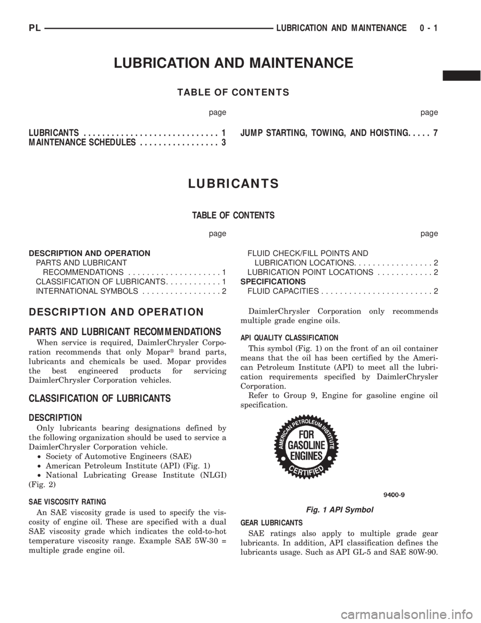
LUBRICATION AND MAINTENANCE
TABLE OF CONTENTS
page page
LUBRICANTS............................. 1
MAINTENANCE SCHEDULES................. 3JUMP STARTING, TOWING, AND HOISTING..... 7
LUBRICANTS
TABLE OF CONTENTS
page page
DESCRIPTION AND OPERATION
PARTS AND LUBRICANT
RECOMMENDATIONS....................1
CLASSIFICATION OF LUBRICANTS............1
INTERNATIONAL SYMBOLS.................2FLUID CHECK/FILL POINTS AND
LUBRICATION LOCATIONS.................2
LUBRICATION POINT LOCATIONS............2
SPECIFICATIONS
FLUID CAPACITIES........................2
DESCRIPTION AND OPERATION
PARTS AND LUBRICANT RECOMMENDATIONS
When service is required, DaimlerChrysler Corpo-
ration recommends that only Mopartbrand parts,
lubricants and chemicals be used. Mopar provides
the best engineered products for servicing
DaimlerChrysler Corporation vehicles.
CLASSIFICATION OF LUBRICANTS
DESCRIPTION
Only lubricants bearing designations defined by
the following organization should be used to service a
DaimlerChrysler Corporation vehicle.
²Society of Automotive Engineers (SAE)
²American Petroleum Institute (API) (Fig. 1)
²National Lubricating Grease Institute (NLGI)
(Fig. 2)
SAE VISCOSITY RATING
An SAE viscosity grade is used to specify the vis-
cosity of engine oil. These are specified with a dual
SAE viscosity grade which indicates the cold-to-hot
temperature viscosity range. Example SAE 5W-30 =
multiple grade engine oil.DaimlerChrysler Corporation only recommends
multiple grade engine oils.
API QUALITY CLASSIFICATION
This symbol (Fig. 1) on the front of an oil container
means that the oil has been certified by the Ameri-
can Petroleum Institute (API) to meet all the lubri-
cation requirements specified by DaimlerChrysler
Corporation.
Refer to Group 9, Engine for gasoline engine oil
specification.
GEAR LUBRICANTS
SAE ratings also apply to multiple grade gear
lubricants. In addition, API classification defines the
lubricants usage. Such as API GL-5 and SAE 80W-90.
Fig. 1 API Symbol
PLLUBRICATION AND MAINTENANCE 0 - 1
Page 3 of 1285
LUBRICANTS AND GREASES
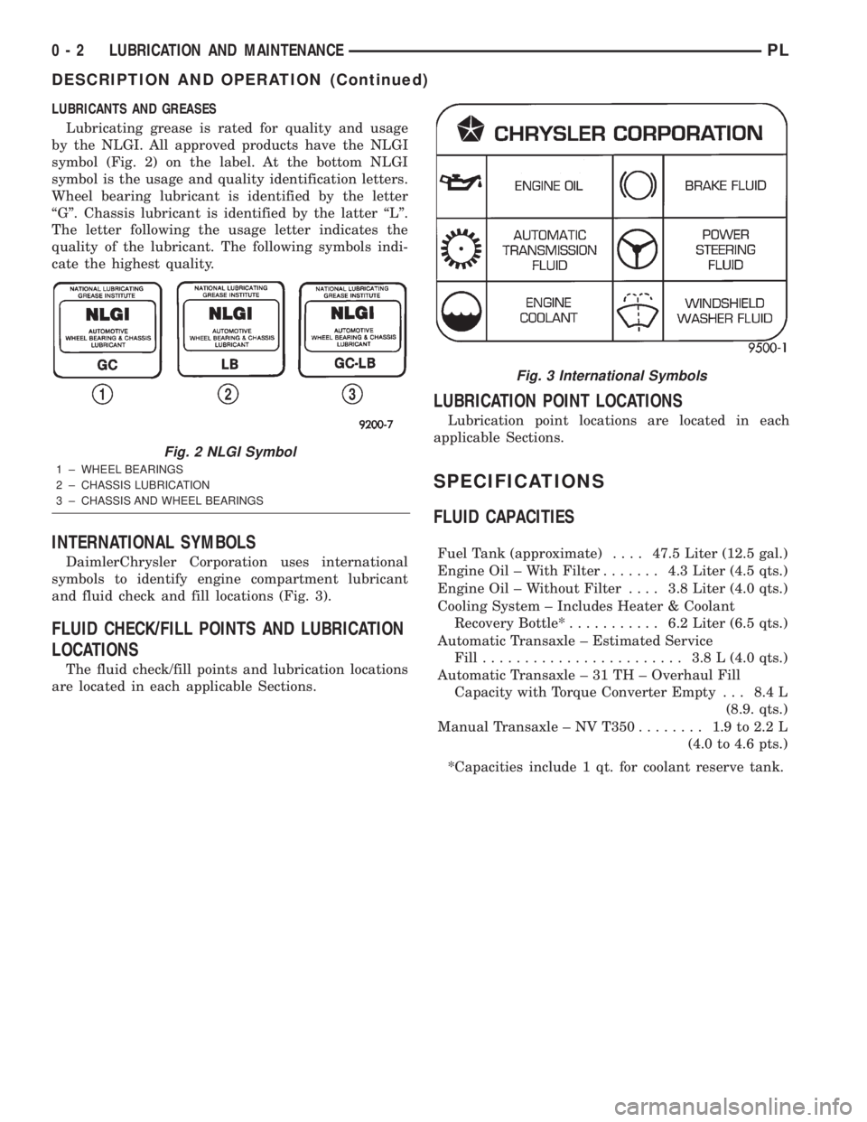
Lubricating grease is rated for quality and usage
by the NLGI. All approved products have the NLGI
symbol (Fig. 2) on the label. At the bottom NLGI
symbol is the usage and quality identification letters.
Wheel bearing lubricant is identified by the letter
ªGº. Chassis lubricant is identified by the latter ªLº.
The letter following the usage letter indicates the
quality of the lubricant. The following symbols indi-
cate the highest quality.
INTERNATIONAL SYMBOLS
DaimlerChrysler Corporation uses international
symbols to identify engine compartment lubricant
and fluid check and fill locations (Fig. 3).
FLUID CHECK/FILL POINTS AND LUBRICATION
LOCATIONS
The fluid check/fill points and lubrication locations
are located in each applicable Sections.
LUBRICATION POINT LOCATIONS
Lubrication point locations are located in each
applicable Sections.
SPECIFICATIONS
FLUID CAPACITIES
Fuel Tank (approximate)....47.5 Liter (12.5 gal.)
Engine Oil ± With Filter....... 4.3Liter (4.5 qts.)
Engine Oil ± Without Filter.... 3.8Liter (4.0 qts.)
Cooling System ± Includes Heater & Coolant
Recovery Bottle*........... 6.2Liter (6.5 qts.)
Automatic Transaxle ± Estimated Service
Fill........................ 3.8L(4.0 qts.)
Automatic Transaxle ± 31 TH ± Overhaul Fill
Capacity with Torque Converter Empty . . . 8.4 L
(8.9. qts.)
Manual Transaxle ± NV T350........ 1.9to2.2L
(4.0 to 4.6 pts.)
*Capacities include 1 qt. for coolant reserve tank.
Fig. 2 NLGI Symbol
1 ± WHEEL BEARINGS
2 ± CHASSIS LUBRICATION
3 ± CHASSIS AND WHEEL BEARINGS
Fig. 3 International Symbols
0 - 2 LUBRICATION AND MAINTENANCEPL
DESCRIPTION AND OPERATION (Continued)
Page 5 of 1285

30,000 Miles (48 000 km) or at 24 months
²Change the engine oil.
²Replace the engine oil filter.
²Lubricate the front suspension lower ball joint.
²Inspect the tie rod ends and boot seals.
²Adjust the drive belt tension.
²Replace the engine air cleaner element (fil-
ter).
²Replace the engine spark plugs
²Change the automatic transaxle fluid.
37,500 Miles (60 000 km) or at 30 months
²Change the engine oil.
²Replace the engine oil filter.
45,000 Miles (72 000 km) or at 36 months
²Change the engine oil.
²Replace the engine oil filter.
²Inspect the front brake pads and rear brake lin-
ings.
²Adjust the drive belt tension.
²Flush and replace the engine coolant at 36
months, regardless of mileage.
52,500 Miles (84 000 km) or at 42 months
²Change the engine oil.
²Replace the engine oil filter.
²Flush and replace the engine coolant if not done
at 36 months.
60,000 Miles (96 000 km) or at 48 months
²Change the engine oil.
²Replace the engine oil filter.
²Check the PCV valve and replace, if neces-
sary. Not required if previously changed.*
²Lubricate the front suspension lower ball joints.
²Replace the drive belts.
²Replace the engine air cleaner element (fil-
ter).
²Replace the ignition cables.
²Replace the spark plugs.
²Change the automatic transaxle fluid.
67,500 Miles (108 000 km) or at 54 months
²Change the engine oil.
²Replace the engine oil filter.
²Inspect the front brake pads and rear brake lin-
ings.
75,000 Miles (120 000 km) or at 60 months
²Change the engine oil.
²Replace the engine oil filter.
²Adjust the drive belt tension.
²Flush and replace engine coolant if has been
30,000 miles (48 000 km) or 24 months since last
change.
82,500 Miles (132 000 km) or at 66 months
²Change the engine oil.
²Replace the engine oil filter.
²Flush and replace engine coolant if it has been
30,000 miles (48 000 km) or 24 months since last
change.
90,000 Miles (144 000 km) or at 72 months
²Change the engine oil.
²Replace the engine oil filter.
²Check the PCV valve and replace, if neces-
sary. Not required if previously changed.*
²Lubricate the front suspension lower ball joints.
²Inspect the front brake pads and rear brake lin-
ings.
²Adjust the drive belt tension.
²Replace the engine air cleaner element (fil-
ter).
²Replace the spark plugs.
²Inspect the serpentine drive belt, replace if nec-
essary. This maintenance is not required if the belt
was previously replaced.
²Change the automatic transaxle fluid.
97,500 Miles (156 000 km) or at 78 months
²Change the engine oil.
²Replace the engine oil filter.
105,000 Miles (168 000 km) or at 84 months
²Change the engine oil.
²Replace the engine oil filter.
²Replace the engine timing belt.
²Adjust the drive belt tension.
*This maintenance is recommended by Daimler-
Chrysler Corporation to the owner but is not
required to maintain the emissions warranty.
NOTE: Inspection and service should also be per-
formed anytime a malfunction is observed or sus-
pected. Retain all receipts.
SCHEDULE ± B
3,000 Miles (5 000 km)
²Change the engine oil.
6,000 Miles (10 000 km)
²Change the engine oil.
²Replace the engine oil filter.
9,000 Miles (14 000 km)
²Change the engine oil.
²Inspect the front brake pads and rear brake lin-
ings.
0 - 4 LUBRICATION AND MAINTENANCEPL
SPECIFICATIONS (Continued)
Page 14 of 1285
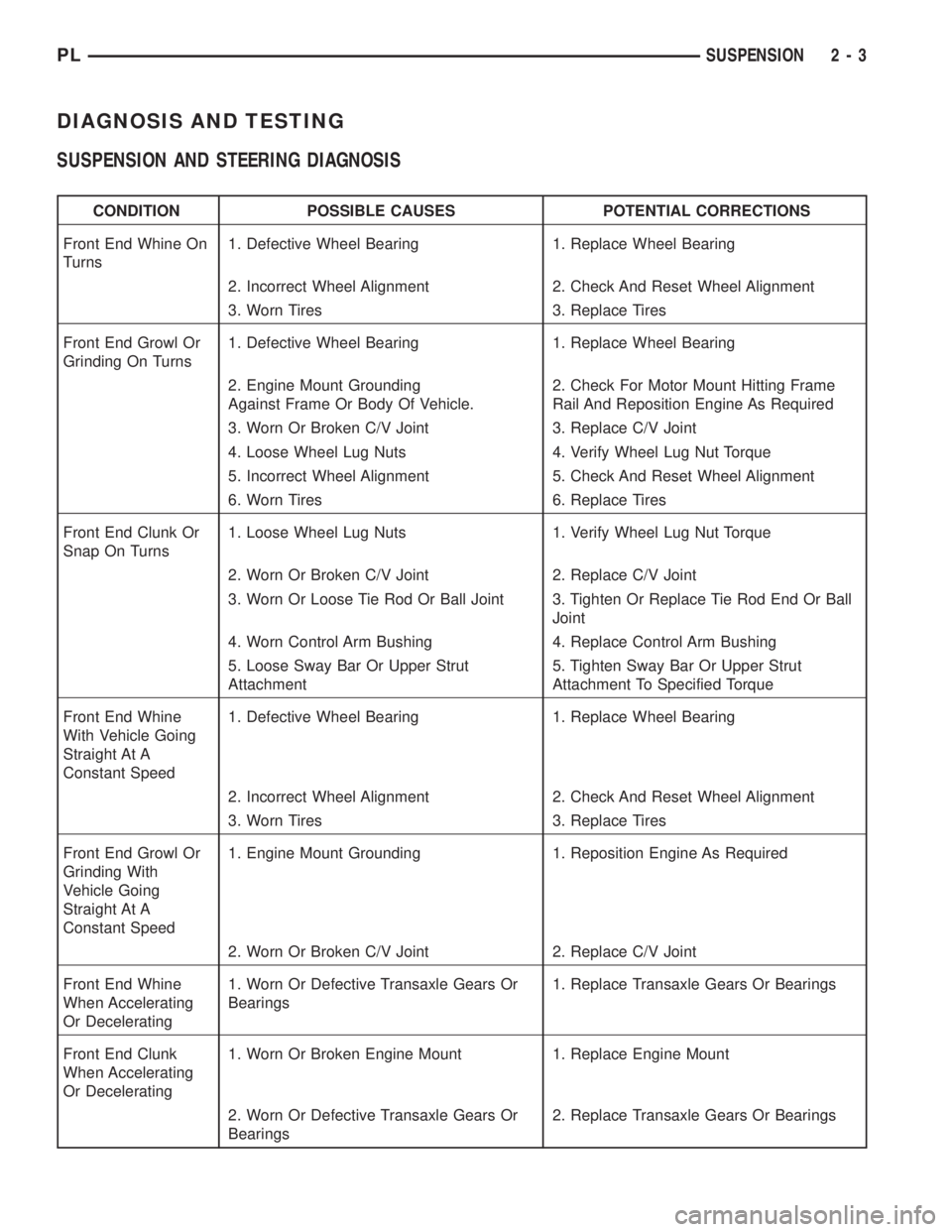
DIAGNOSIS AND TESTING
SUSPENSION AND STEERING DIAGNOSIS
CONDITION POSSIBLE CAUSES POTENTIAL CORRECTIONS
Front End Whine On
Turns1. Defective Wheel Bearing 1. Replace Wheel Bearing
2. Incorrect Wheel Alignment 2. Check And Reset Wheel Alignment
3. Worn Tires 3. Replace Tires
Front End Growl Or
Grinding On Turns1. Defective Wheel Bearing 1. Replace Wheel Bearing
2. Engine Mount Grounding
Against Frame Or Body Of Vehicle.2. Check For Motor Mount Hitting Frame
Rail And Reposition Engine As Required
3. Worn Or Broken C/V Joint 3. Replace C/V Joint
4. Loose Wheel Lug Nuts 4. Verify Wheel Lug Nut Torque
5. Incorrect Wheel Alignment 5. Check And Reset Wheel Alignment
6. Worn Tires 6. Replace Tires
Front End Clunk Or
Snap On Turns1. Loose Wheel Lug Nuts 1. Verify Wheel Lug Nut Torque
2. Worn Or Broken C/V Joint 2. Replace C/V Joint
3. Worn Or Loose Tie Rod Or Ball Joint 3. Tighten Or Replace Tie Rod End Or Ball
Joint
4. Worn Control Arm Bushing 4. Replace Control Arm Bushing
5. Loose Sway Bar Or Upper Strut
Attachment5. Tighten Sway Bar Or Upper Strut
Attachment To Specified Torque
Front End Whine
With Vehicle Going
Straight At A
Constant Speed1. Defective Wheel Bearing 1. Replace Wheel Bearing
2. Incorrect Wheel Alignment 2. Check And Reset Wheel Alignment
3. Worn Tires 3. Replace Tires
Front End Growl Or
Grinding With
Vehicle Going
Straight At A
Constant Speed1. Engine Mount Grounding 1. Reposition Engine As Required
2. Worn Or Broken C/V Joint 2. Replace C/V Joint
Front End Whine
When Accelerating
Or Decelerating1. Worn Or Defective Transaxle Gears Or
Bearings1. Replace Transaxle Gears Or Bearings
Front End Clunk
When Accelerating
Or Decelerating1. Worn Or Broken Engine Mount 1. Replace Engine Mount
2. Worn Or Defective Transaxle Gears Or
Bearings2. Replace Transaxle Gears Or Bearings
PLSUSPENSION 2 - 3
Page 15 of 1285
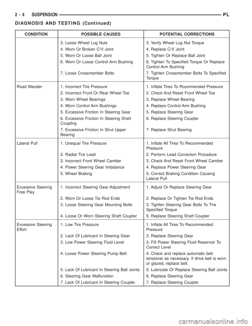
CONDITION POSSIBLE CAUSES POTENTIAL CORRECTIONS
3. Loose Wheel Lug Nuts 3. Verify Wheel Lug Nut Torque
4. Worn Or Broken C/V Joint 4. Replace C/V Joint
5. Worn Or Loose Ball Joint 5. Tighten Or Replace Ball Joint
6. Worn Or Loose Control Arm Bushing 6. Tighten To Specified Torque Or Replace
Control Arm Bushing
7. Loose Crossmember Bolts 7. Tighten Crossmember Bolts To Specified
Torque
Road Wander 1. Incorrect Tire Pressure 1. Inflate Tires To Rcommended Pressure
2. Incorrect Front Or Rear Wheel Toe 2. Check And Reset Front Wheel Toe
3. Worn Wheel Bearings 3. Replace Wheel Bearing
4. Worn Control Arm Bushings 4. Replace Control Arm Bushing
5. Excessive Friction In Steering Gear 5. Replace Steering Gear
6. Excessive Friction In Steering Shaft
Coupling6. Replace Steering Coupler
7. Excessive Friction In Strut Upper
Bearing7. Replace Strut Bearing
Lateral Pull 1. Unequal Tire Pressure 1. Inflate All Tires To Recommended
Pressure
2. Radial Tire Lead 2. Perform Lead Correction Procedure
3. Incorrect Front Wheel Camber 3. Check And Reset Front Wheel Camber
4. Power Steering Gear Imbalance 4. Replace Power Steering Gear
5. Wheel Braking 5. Correct Braking Condition Causing
Lateral Pull
Excessive Steering
Free Play1. Incorrect Steering Gear Adjustment 1. Adjust Or Replace Steering Gear
2. Worn Or Loose Tie Rod Ends 2. Replace Or Tighten Tie Rod Ends
3. Loose Steering Gear Mounting Bolts 3. Tighten Steering Gear Bolts To The
Specified Torque
4. Loose Or Worn Steering Shaft Coupler 5. Replace Steering Shaft Coupler
Excessive Steering
Effort1. Low Tire Pressure 1. Inflate All Tires To Recommended
Pressure
2. Lack Of Lubricant In Steering Gear 2. Replace Steering Gear
3. Low Power Steering Fluid Level 3. Fill Power Steering Fluid Reservoir To
Correct Level
4. Loose Power Steering Pump Belt 4. Check and replace automatic belt
tensioner as necessary. If drive belt is worn
or glazed, replace belt.
5. Lack Of Lubricant In Steering Ball Joints 5. Lubricate Or Replace Steering Ball Joints
6. Steering Gear Malfunction 6. Replace Steering Gear
7. Lack Of Lubricant In Steering Coupler 7. Replace Steering Coupler
2 - 4 SUSPENSIONPL
DIAGNOSIS AND TESTING (Continued)
Page 18 of 1285
(4) Install a nut provided in adjustment package
on the replacement bolt. Tighten the nut until it's
snug, but still allowing the knuckle to slide in the
clevis bracket.
(5) Remove the original lower bolt.
(6) Install a bolt from the adjustment package into
the bottom hole of the strut clevis bracket. Install the
bolt from the rear.
(7) Install a nut provided in adjustment package
on the replacement bolt. Tighten the nut until it's
snug.
(8) Reinstall the tire and wheel assembly.
(9) Perform the above procedure to any of the
remaining struts as required.
(10) Lower the vehicle and jounce the front and
rear of the vehicle.
(11) Adjust the front or rear camber to the pre-
ferred setting by pushing or pulling on the top of the
tire. When camber is set to specifications, tighten the
upper and lower strut clevis bracket bolts. Again
jounce the front and rear of the vehicle, then verify
the camber settings.
(12) Torque front strut clevis bracket-to-steering
knuckle attaching bolts to 53 N´m (40 ft. lbs.), plus
an additional 1/4 turn after the torque is met. Torque
the rear strut clevis bracket-to-rear knuckle attach-
ing bolts to 95 N´m (70 ft. lbs.).
(13) Once camber is within specifications, adjust
toe to meet the preferred specification setting. Refer
to TOE within this wheel alignment service proce-
dure.
TOE
(1) Center the steering wheel and lock it in place
using a steering wheel clamp.
NOTE: When performing the toe setting procedure,
make sure the rear toe is set to the preferred spec-
ification before setting the front toe to the preferred
specification.
REAR TOE
(1) Loosen the nuts on the left and right rear lat-
eral link attaching bolts at the rear crossmember as
necessary to allow rotation of the rear toe adjustment
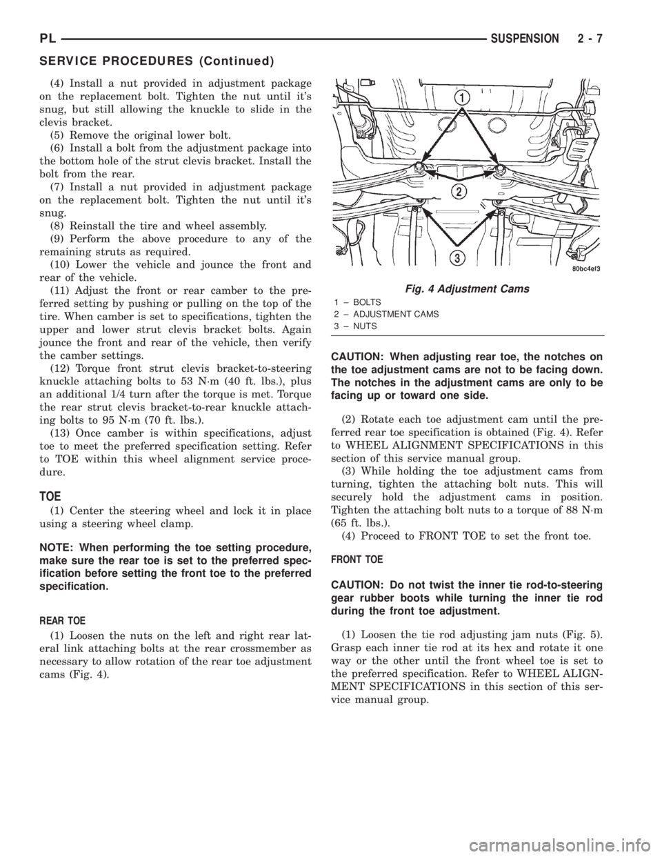
cams (Fig. 4).CAUTION: When adjusting rear toe, the notches on
the toe adjustment cams are not to be facing down.
The notches in the adjustment cams are only to be
facing up or toward one side.
(2) Rotate each toe adjustment cam until the pre-
ferred rear toe specification is obtained (Fig. 4). Refer
to WHEEL ALIGNMENT SPECIFICATIONS in this
section of this service manual group.
(3) While holding the toe adjustment cams from
turning, tighten the attaching bolt nuts. This will
securely hold the adjustment cams in position.
Tighten the attaching bolt nuts to a torque of 88 N´m
(65 ft. lbs.).
(4) Proceed to FRONT TOE to set the front toe.
FRONT TOE
CAUTION: Do not twist the inner tie rod-to-steering
gear rubber boots while turning the inner tie rod
during the front toe adjustment.
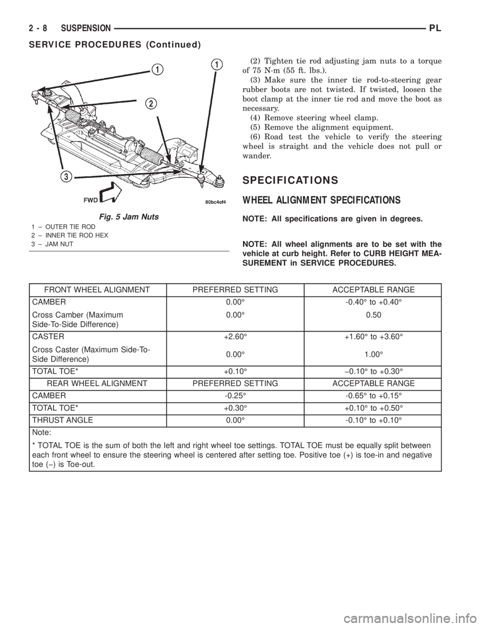
(1) Loosen the tie rod adjusting jam nuts (Fig. 5).
Grasp each inner tie rod at its hex and rotate it one
way or the other until the front wheel toe is set to
the preferred specification. Refer to WHEEL ALIGN-
MENT SPECIFICATIONS in this section of this ser-
vice manual group.
Fig. 4 Adjustment Cams
1 ± BOLTS
2 ± ADJUSTMENT CAMS
3 ± NUTS
PLSUSPENSION 2 - 7
SERVICE PROCEDURES (Continued)
Page 19 of 1285
(2) Tighten tie rod adjusting jam nuts to a torque
of 75 N´m (55 ft. lbs.).
(3) Make sure the inner tie rod-to-steering gear
rubber boots are not twisted. If twisted, loosen the
boot clamp at the inner tie rod and move the boot as
necessary.
(4) Remove steering wheel clamp.
(5) Remove the alignment equipment.
(6) Road test the vehicle to verify the steering
wheel is straight and the vehicle does not pull or
wander.
SPECIFICATIONS
WHEEL ALIGNMENT SPECIFICATIONS
NOTE: All specifications are given in degrees.
NOTE: All wheel alignments are to be set with the
vehicle at curb height. Refer to CURB HEIGHT MEA-
SUREMENT in SERVICE PROCEDURES.
FRONT WHEEL ALIGNMENT PREFERRED SETTING ACCEPTABLE RANGE
CAMBER 0.00É -0.40É to +0.40É
Cross Camber (Maximum
Side-To-Side Difference)0.00É 0.50
CASTER +2.60É +1.60É to +3.60É
Cross Caster (Maximum Side-To-
Side Difference)0.00É 1.00É
TOTAL TOE* +0.10É þ0.10É to +0.30É
REAR WHEEL ALIGNMENT PREFERRED SETTING ACCEPTABLE RANGE
CAMBER -0.25É -0.65É to +0.15É
TOTAL TOE* +0.30É +0.10É to +0.50É
THRUST ANGLE 0.00É -0.10É to +0.10É
Note:
* TOTAL TOE is the sum of both the left and right wheel toe settings. TOTAL TOE must be equally split between
each front wheel to ensure the steering wheel is centered after setting toe. Positive toe (+) is toe-in and negative
toe (þ) is Toe-out.
Fig. 5 Jam Nuts
1 ± OUTER TIE ROD
2 ± INNER TIE ROD HEX
3 ± JAM NUT
2 - 8 SUSPENSIONPL
SERVICE PROCEDURES (Continued)
Page 22 of 1285
For more information on the description and oper-
ation of an individual component, refer to the appli-
cable component heading in this section.
STRUT ASSEMBLY (FRONT)
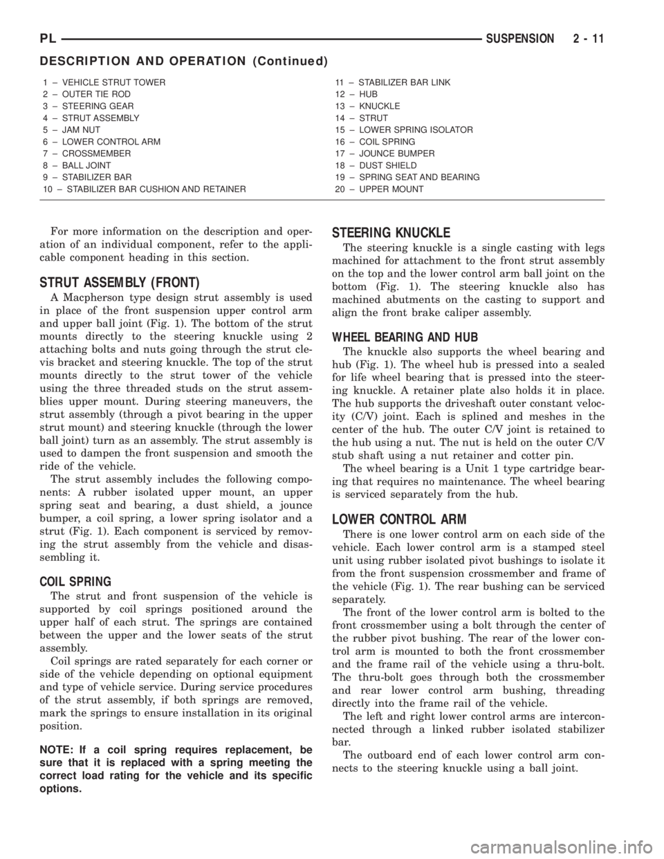
A Macpherson type design strut assembly is used
in place of the front suspension upper control arm
and upper ball joint (Fig. 1). The bottom of the strut
mounts directly to the steering knuckle using 2
attaching bolts and nuts going through the strut cle-
vis bracket and steering knuckle. The top of the strut
mounts directly to the strut tower of the vehicle
using the three threaded studs on the strut assem-
blies upper mount. During steering maneuvers, the
strut assembly (through a pivot bearing in the upper
strut mount) and steering knuckle (through the lower
ball joint) turn as an assembly. The strut assembly is
used to dampen the front suspension and smooth the
ride of the vehicle.
The strut assembly includes the following compo-
nents: A rubber isolated upper mount, an upper
spring seat and bearing, a dust shield, a jounce
bumper, a coil spring, a lower spring isolator and a
strut (Fig. 1). Each component is serviced by remov-
ing the strut assembly from the vehicle and disas-
sembling it.
COIL SPRING
The strut and front suspension of the vehicle is
supported by coil springs positioned around the
upper half of each strut. The springs are contained
between the upper and the lower seats of the strut
assembly.
Coil springs are rated separately for each corner or
side of the vehicle depending on optional equipment
and type of vehicle service. During service procedures
of the strut assembly, if both springs are removed,
mark the springs to ensure installation in its original
position.
NOTE: If a coil spring requires replacement, be
sure that it is replaced with a spring meeting the
correct load rating for the vehicle and its specific
options.
STEERING KNUCKLE
The steering knuckle is a single casting with legs
machined for attachment to the front strut assembly
on the top and the lower control arm ball joint on the
bottom (Fig. 1). The steering knuckle also has
machined abutments on the casting to support and
align the front brake caliper assembly.
WHEEL BEARING AND HUB
The knuckle also supports the wheel bearing and
hub (Fig. 1). The wheel hub is pressed into a sealed
for life wheel bearing that is pressed into the steer-
ing knuckle. A retainer plate also holds it in place.
The hub supports the driveshaft outer constant veloc-
ity (C/V) joint. Each is splined and meshes in the
center of the hub. The outer C/V joint is retained to
the hub using a nut. The nut is held on the outer C/V
stub shaft using a nut retainer and cotter pin.
The wheel bearing is a Unit 1 type cartridge bear-
ing that requires no maintenance. The wheel bearing
is serviced separately from the hub.
LOWER CONTROL ARM
There is one lower control arm on each side of the
vehicle. Each lower control arm is a stamped steel
unit using rubber isolated pivot bushings to isolate it
from the front suspension crossmember and frame of
the vehicle (Fig. 1). The rear bushing can be serviced
separately.
The front of the lower control arm is bolted to the
front crossmember using a bolt through the center of
the rubber pivot bushing. The rear of the lower con-
trol arm is mounted to both the front crossmember
and the frame rail of the vehicle using a thru-bolt.
The thru-bolt goes through both the crossmember
and rear lower control arm bushing, threading
directly into the frame rail of the vehicle.
The left and right lower control arms are intercon-
nected through a linked rubber isolated stabilizer
bar.
The outboard end of each lower control arm con-
nects to the steering knuckle using a ball joint.
1 ± VEHICLE STRUT TOWER
2 ± OUTER TIE ROD
3 ± STEERING GEAR
4 ± STRUT ASSEMBLY
5 ± JAM NUT
6 ± LOWER CONTROL ARM
7 ± CROSSMEMBER
8 ± BALL JOINT
9 ± STABILIZER BAR
10 ± STABILIZER BAR CUSHION AND RETAINER11 ± STABILIZER BAR LINK
12 ± HUB
13 ± KNUCKLE
14 ± STRUT
15 ± LOWER SPRING ISOLATOR
16 ± COIL SPRING
17 ± JOUNCE BUMPER
18 ± DUST SHIELD
19 ± SPRING SEAT AND BEARING
20 ± UPPER MOUNT
PLSUSPENSION 2 - 11
DESCRIPTION AND OPERATION (Continued)