2000 DODGE NEON transmission oil
[x] Cancel search: transmission oilPage 241 of 1285
IGNITION INTERLOCK
OPERATION
All vehicles equipped with automatic transaxles
have an interlock system. The system prevents shift-
ing the vehicle out of Park unless the ignition lock
cylinder is in the Off, Run or Start position. In addi-
tion, the operator cannot rotate the key to the lock
position unless the shifter is in the park position. On
vehicles equipped with floor shift refer to the - Tran-
saxle for Automatic Transmission Shifter/Ignition
Interlock.
REMOVAL AND INSTALLATION
SPARK PLUG SERVICE
Failure to route the cables properly could cause the
radio to reproduce ignition noise, cross ignition of the
spark plugs or short circuit the cables to ground.
REMOVAL
REMOVE CABLES FROM COIL FIRST.
Always remove the spark plug cable by grasping
the top of the spark plug insulator, turning the boot
1/2 turn and pulling straight up in a steady motion.
(1) Remove the spark plug using a quality socket
with a rubber or foam insert.
(2) Inspect the spark plug condition.
INSTALLATION
(1) To avoid cross threading, start the spark plug
into the cylinder head by hand.
(2) Tighten spark plugs to 28 N´m (20 ft. lbs.)
torque.
(3) Install spark plug insulators over spark plugs.
Ensure the top of the spark plug insulator covers the
upper end of the spark plug tube.
Reconnect to coil.
SPARK PLUG CABLE SERVICE
Failure to route the cables properly could cause the
radio to reproduce ignition noise, cross ignition of the
spark plugs or short circuit the cables to ground.
REMOVAL
Remove spark plug cable from coil first.
Always remove the spark plug cable by grasping
the top of the spark plug insulator, turning the boot
1/2 turn and pulling straight up in a steady motion.
INSTALLATION
Install spark plug insulators over spark plugs.
Ensure the top of the spark plug insulator covers the
upper end of the spark plug tube. The connect theother end to coil pack. Be sure that dual plastic clip
holds the cables off of the valve cover.
IGNITION COIL
The electronic ignition coil pack attaches directly
to the valve cover (Fig. 11).
REMOVAL
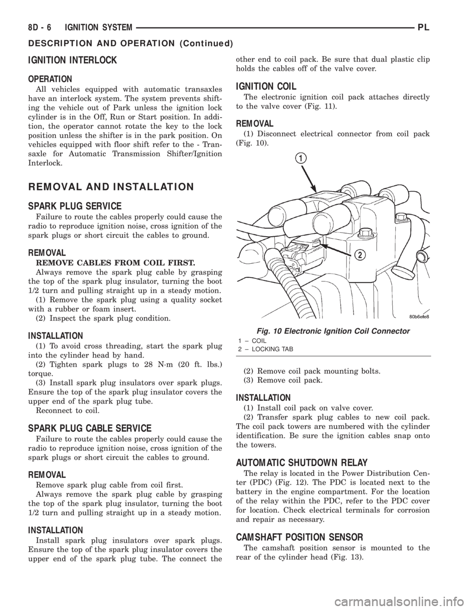
(1) Disconnect electrical connector from coil pack
(Fig. 10).
(2) Remove coil pack mounting bolts.
(3) Remove coil pack.
INSTALLATION
(1) Install coil pack on valve cover.
(2) Transfer spark plug cables to new coil pack.
The coil pack towers are numbered with the cylinder
identification. Be sure the ignition cables snap onto
the towers.
AUTOMATIC SHUTDOWN RELAY
The relay is located in the Power Distribution Cen-
ter (PDC) (Fig. 12). The PDC is located next to the
battery in the engine compartment. For the location
of the relay within the PDC, refer to the PDC cover
for location. Check electrical terminals for corrosion
and repair as necessary.
CAMSHAFT POSITION SENSOR
The camshaft position sensor is mounted to the
rear of the cylinder head (Fig. 13).
Fig. 10 Electronic Ignition Coil Connector
1 ± COIL
2 ± LOCKING TAB
8D - 6 IGNITION SYSTEMPL
DESCRIPTION AND OPERATION (Continued)
Page 724 of 1285
ENGINE
TABLE OF CONTENTS
page page
STANDARD SERVICE PROCEDURES........... 1
ENGINE DIAGNOSIS........................ 82.0L SOHC ENGINE....................... 15
STANDARD SERVICE PROCEDURES
TABLE OF CONTENTS
page page
GENERAL INFORMATION
FORM-IN-PLACE GASKETS & SEALERS........1
ENGINE GASKET SURFACE PREPARATION.....2
CRANKSHAFT DAMPER BOLT ACCESS PLUG . . . 2
ENGINE CORE PLUGS.....................2
ENGINE PERFORMANCE...................3HONING CYLINDER BORES.................3
MEASURING WITH PLASTIGAGE.............4
REPAIR OF DAMAGED OR WORN THREADS....5
HYDROSTATIC LOCKED ENGINE.............5
CHECKING ENGINE OIL LEVEL..............6
ENGINE OIL SERVICE......................7
GENERAL INFORMATION
FORM-IN-PLACE GASKETS & SEALERS
There are numerous places where form-in-place
gaskets are used on the engine. Care must be taken
when applying form-in-place gaskets to assure
obtaining the desired results.Do not use form-in-
place gasket material unless specified.Bead size,
continuity, and location are of great importance. Too
thin a bead can result in leakage while too much can
result in spill-over which can break off and obstruct
fluid feed lines. A continuous bead of the proper
width is essential to obtain a leak-free gasket.
There are numerous types of form-in-place gasket
materials that are used in the engine area. Mopart
Engine RTV GEN II, MopartATF-RTV, and Mopart
Gasket Maker gasket materials, each have different
properties and can not be used in place of the other.
MOPARtENGINE RTV GEN II
MopartEngine RTV GEN II is used to seal com-
ponents exposed to engine oil. This material is a spe-
cially designed black silicone rubber RTV that
retains adhesion and sealing properties when
exposed to engine oil. Moisture in the air causes the
material to cure. This material is available in three
ounce tubes and has a shelf life of one year. After one
year this material will not properly cure. Alwaysinspect the package for the expiration date before
use.
MOPARtATF RTV
MopartATF RTV is a specifically designed black
silicone rubber RTV that retains adhesion and seal-
ing properties to seal components exposed to auto-
matic transmission fluid, engine coolants, and
moisture. This material is available in three ounce
tubes and has a shelf life of one year. After one year
this material will not properly cure. Always inspect
the package for the expiration date before use.
MOPARtGASKET MAKER
MopartGasket Maker is an anaerobic type gasket
material. The material cures in the absence of air
when squeezed between two metallic surfaces. It will
not cure if left in the uncovered tube. The anaerobic
material is for use between two machined surfaces.
Do not use on flexible metal flanges.
MOPARtBED PLATE SEALANT
MopartBed Plate Sealant is a unique (green-in-
color) anaerobic type gasket material that is specially
made to seal the area between the bedplate and cyl-
inder block without disturbing the bearing clearance
or alignment of these components. The material
cures slowly in the absence of air when torqued
between two metallic surfaces, and will rapidly cure
when heat is applied.
PLENGINE 9 - 1
Page 727 of 1285
will clean up a bore and maintain the required lim-
its.
(2) Deglazing of the cylinder walls may be done
using a cylinder surfacing hone, recommended tool
C-3501 or equivalent, equipped with 280 grit stones,
if the cylinder bore is straight and round. 20±60
strokes depending on the bore condition, will be suf-
ficient to provide a satisfactory surface. Inspect cyl-
inder walls after each 20 strokes, using a light
honing oil.Do not use engine or transmission oil,
mineral spirits or kerosene.
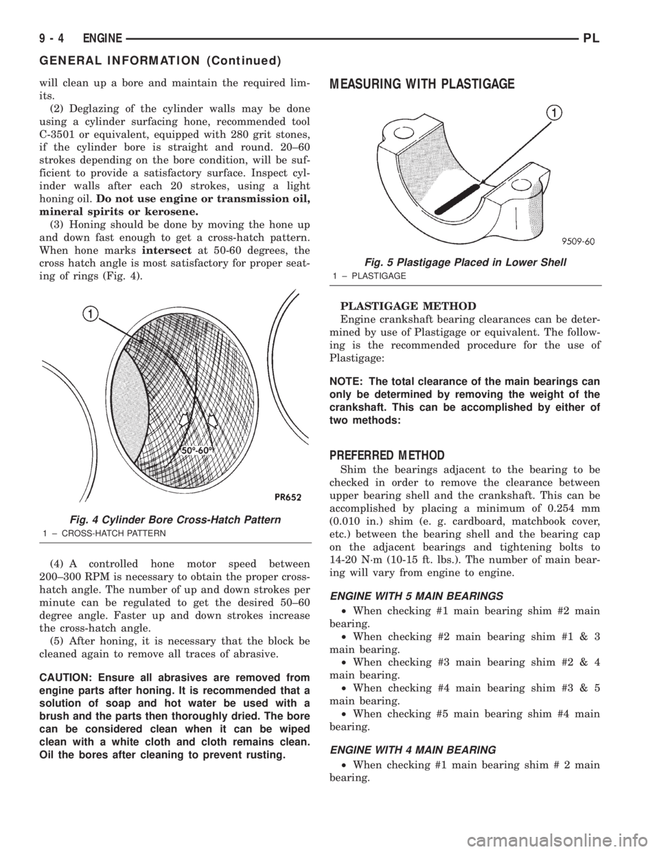
(3) Honing should be done by moving the hone up
and down fast enough to get a cross-hatch pattern.
When hone marksintersectat 50-60 degrees, the
cross hatch angle is most satisfactory for proper seat-
ing of rings (Fig. 4).
(4) A controlled hone motor speed between
200±300 RPM is necessary to obtain the proper cross-
hatch angle. The number of up and down strokes per
minute can be regulated to get the desired 50±60
degree angle. Faster up and down strokes increase
the cross-hatch angle.
(5) After honing, it is necessary that the block be
cleaned again to remove all traces of abrasive.
CAUTION: Ensure all abrasives are removed from
engine parts after honing. It is recommended that a
solution of soap and hot water be used with a
brush and the parts then thoroughly dried. The bore
can be considered clean when it can be wiped
clean with a white cloth and cloth remains clean.
Oil the bores after cleaning to prevent rusting.MEASURING WITH PLASTIGAGE
PLASTIGAGE METHOD
Engine crankshaft bearing clearances can be deter-
mined by use of Plastigage or equivalent. The follow-
ing is the recommended procedure for the use of
Plastigage:
NOTE: The total clearance of the main bearings can
only be determined by removing the weight of the
crankshaft. This can be accomplished by either of
two methods:
PREFERRED METHOD
Shim the bearings adjacent to the bearing to be
checked in order to remove the clearance between
upper bearing shell and the crankshaft. This can be
accomplished by placing a minimum of 0.254 mm
(0.010 in.) shim (e. g. cardboard, matchbook cover,
etc.) between the bearing shell and the bearing cap
on the adjacent bearings and tightening bolts to
14-20 N´m (10-15 ft. lbs.). The number of main bear-
ing will vary from engine to engine.
ENGINE WITH 5 MAIN BEARINGS
²When checking #1 main bearing shim #2 main
bearing.
²When checking #2 main bearing shim #1 & 3
main bearing.
²When checking #3 main bearing shim #2 & 4
main bearing.
²When checking #4 main bearing shim #3 & 5
main bearing.
²When checking #5 main bearing shim #4 main
bearing.
ENGINE WITH 4 MAIN BEARING
²When checking #1 main bearing shim # 2 main
bearing.
Fig. 4 Cylinder Bore Cross-Hatch Pattern
1 ± CROSS-HATCH PATTERN
Fig. 5 Plastigage Placed in Lower Shell
1 ± PLASTIGAGE
9 - 4 ENGINEPL
GENERAL INFORMATION (Continued)
Page 733 of 1285
make sure the dye is thoroughly mixed as indicated
with a bright yellow color under a black light.
(3) Using a black light, inspect the entire engine
for fluorescent dye, particularly at the suspected area
of oil leak. If the oil leak is found and identified,
repair per service manual instructions.
(4) If dye is not observed, drive the vehicle at var-
ious speeds for approximately 24 km (15 miles), and
repeat inspection.
(5)If the oil leak source is not positively
identified at this time, proceed with the air leak
detection test method as follows:
²Disconnect the fresh air hose (makeup air) at
the cylinder head cover and plug or cap the nipple on
the cover.
²Remove the PCV valve hose from the cylinder
head cover. Cap or plug the PCV valve nipple on the
cover.
²Attach an air hose with pressure gauge and reg-
ulator to the dipstick tube.
CAUTION: Do not subject the engine assembly to
more than 20.6 kpa (3 PSI) of test pressure.
²Gradually apply air pressure from 1 psi to 2.5
psi maximum while applying soapy water at the sus-
pected source. Adjust the regulator to the suitable
test pressure that provides the best bubbles which
will pinpoint the leak source. If the oil leak is
detected and identified, repair per service manual
procedures.
²If the leakage occurs at the crankshaft rear oil
seal area, refer to the section, Inspection for Rear
Seal Area Leak.
(6) If no leaks are detected, turn off the air supply.
Remove the air hose, all plugs, and caps. Install the
PCV valve and CCV hose. Proceed to next step.
(7) Clean the oil off the suspect oil leak area using
a suitable solvent. Drive the vehicle at various
speeds approximately 24 km (15 miles). Inspect the
engine for signs of an oil leak by using a black light.
INSPECTION FOR REAR SEAL AREA LEAKS
Since it is sometimes difficult to determine the
source of an oil leak in the rear seal area of theengine, a more involved inspection is necessary. The
following steps should be followed to help pinpoint
the source of the leak.
If the leakage occurs at the crankshaft rear oil seal
area:
(1) Disconnect the battery.
(2) Raise the vehicle.
(3) Remove torque converter or clutch housing
cover and inspect rear of block for evidence of oil.
Use a black light to check for the oil leak. If a leak is
present in this area remove transmission for further
inspection.
(a) Circular spray pattern generally indicates
seal leakage or crankshaft damage.
(b) Where leakage tends to run straight down,
possible causes are a porous block, oil galley cup
plug, bedplate to cylinder block mating surfaces
and seal bore. See proper repair procedures for
these items.
(4) If no leaks are detected, pressurized the crank-
case as previously described.
CAUTION: Do not exceed 20.6 kPa (3 psi).
(5) If the leak is not detected, very slowly turn the
crankshaft and watch for leakage. If a leak is
detected between the crankshaft and seal while
slowly turning the crankshaft, it is possible the
crankshaft seal surface is damaged. The seal area on
the crankshaft could have minor nicks or scratches
that can be polished out with emery cloth.
CAUTION: Use extreme caution when crankshaft
polishing is necessary to remove minor nicks and
scratches. The crankshaft seal flange is especially
machined to complement the function of the rear oil
seal.
(6) For bubbles that remain steady with shaft
rotation, no further inspection can be done until dis-
assembled.
(7) After the oil leak root cause and appropriate
corrective action have been identified, refer to Crank-
shaft Oil SealÐRear for proper replacement proce-
dures.
9 - 10 ENGINEPL
DIAGNOSIS AND TESTING (Continued)
Page 749 of 1285
(4) Discharge air conditioning system, if equipped.
Refer to Group 24, Heating and Air Conditioning for
procedure.
(5) Disconnect the following: air intake duct at
intake manifold, throttle cables, electrical connectors
from throttle body and air cleaner housing.
(6) Remove air cleaner housing assembly.
(7) Remove upper radiator hose and fan module.
Refer to Group 7, Cooling System for procedure.
(8) Remove lower radiator hose.
(9) Disconnect automatic transmission cooler lines
and plug, if equipped.
(10) Disconnect shift linkage, electrical connectors,
and clutch cable, if equipped with manual transaxle.
(11) Disconnect engine wiring harness.
(12) Disconnect positive cable from Power Distri-
bution Center (PDC) and ground wire from vehicle
body.
(13) Disconnect ground wire from the vehicle body-
to-engine at the right side strut tower.
(14) Disconnect heater hoses.
(15) Disconnect vacuum hose from brake booster.
(16) Disconnect coolant reserve/recovery hose.
(17) Remove accessory drive belts. Refer to Group
7, Cooling System for procedure.
(18) Remove power steering pump and reservoir
and set them aside.
(19) Hoist vehicle and remove right inner splash
shield.
(20) Drain engine oil.
(21) Remove front wheels.
(22) Remove axle shafts. Refer to Group 3, Differ-
ential and Driveline for procedure.
(23) Disconnect exhaust system from manifold.
(24) Disconnect the downstream oxygen sensor
connector.
(25) Remove lower engine torque strut.
(26) Remove structural collar. Refer to procedure
in this section.
(27) Lower vehicle and remove A/C compressor.
(28) Raise vehicle enough to allow engine dolly
and cradle, Special Tools 6135 and 6710 to be
installed under vehicle.
(29) Loosen engine support posts to allow move-
ment for positioning onto engine locating holes and
flange on the engine bedplate. Lower vehicle and
position cradle until the engine is resting on support
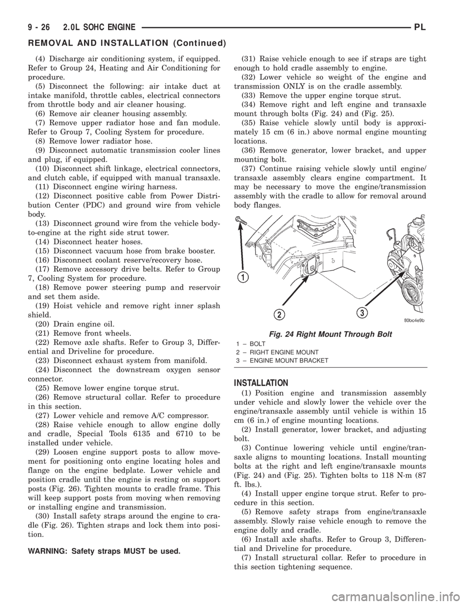
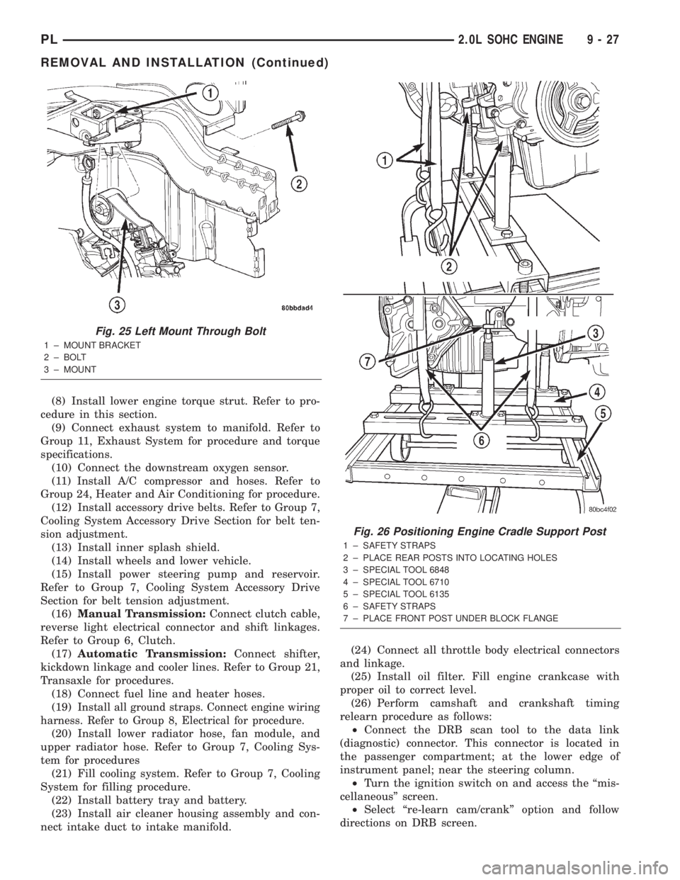
posts (Fig. 26). Tighten mounts to cradle frame. This
will keep support posts from moving when removing
or installing engine and transmission.
(30) Install safety straps around the engine to cra-
dle (Fig. 26). Tighten straps and lock them into posi-
tion.
WARNING: Safety straps MUST be used.(31) Raise vehicle enough to see if straps are tight
enough to hold cradle assembly to engine.
(32) Lower vehicle so weight of the engine and
transmission ONLY is on the cradle assembly.
(33) Remove the upper engine torque strut.
(34) Remove right and left engine and transaxle
mount through bolts (Fig. 24) and (Fig. 25).
(35) Raise vehicle slowly until body is approxi-
mately 15 cm (6 in.) above normal engine mounting
locations.
(36) Remove generator, lower bracket, and upper
mounting bolt.
(37) Continue raising vehicle slowly until engine/
transaxle assembly clears engine compartment. It
may be necessary to move the engine/transmission
assembly with the cradle to allow for removal around
body flanges.
INSTALLATION
(1) Position engine and transmission assembly
under vehicle and slowly lower the vehicle over the
engine/transaxle assembly until vehicle is within 15
cm (6 in.) of engine mounting locations.
(2) Install generator, lower bracket, and adjusting
bolt.
(3) Continue lowering vehicle until engine/tran-
saxle aligns to mounting locations. Install mounting
bolts at the right and left engine/transaxle mounts
(Fig. 24) and (Fig. 25). Tighten bolts to 118 N´m (87
ft. lbs.).
(4) Install upper engine torque strut. Refer to pro-
cedure in this section.
(5) Remove safety straps from engine/transaxle
assembly. Slowly raise vehicle enough to remove the
engine dolly and cradle.
(6) Install axle shafts. Refer to Group 3, Differen-
tial and Driveline for procedure.
(7) Install structural collar. Refer to procedure in
this section tightening sequence.
Fig. 24 Right Mount Through Bolt
1 ± BOLT
2 ± RIGHT ENGINE MOUNT
3 ± ENGINE MOUNT BRACKET
9 - 26 2.0L SOHC ENGINEPL
REMOVAL AND INSTALLATION (Continued)
Page 750 of 1285
(8) Install lower engine torque strut. Refer to pro-
cedure in this section.
(9) Connect exhaust system to manifold. Refer to
Group 11, Exhaust System for procedure and torque
specifications.
(10) Connect the downstream oxygen sensor.
(11) Install A/C compressor and hoses. Refer to
Group 24, Heater and Air Conditioning for procedure.
(12) Install accessory drive belts. Refer to Group 7,
Cooling System Accessory Drive Section for belt ten-
sion adjustment.
(13) Install inner splash shield.
(14) Install wheels and lower vehicle.
(15) Install power steering pump and reservoir.
Refer to Group 7, Cooling System Accessory Drive
Section for belt tension adjustment.
(16)Manual Transmission:Connect clutch cable,
reverse light electrical connector and shift linkages.
Refer to Group 6, Clutch.
(17)Automatic Transmission:Connect shifter,
kickdown linkage and cooler lines. Refer to Group 21,
Transaxle for procedures.
(18) Connect fuel line and heater hoses.
(19)
Install all ground straps. Connect engine wiring
harness. Refer to Group 8, Electrical for procedure.
(20) Install lower radiator hose, fan module, and
upper radiator hose. Refer to Group 7, Cooling Sys-
tem for procedures
(21) Fill cooling system. Refer to Group 7, Cooling
System for filling procedure.
(22) Install battery tray and battery.
(23) Install air cleaner housing assembly and con-
nect intake duct to intake manifold.(24) Connect all throttle body electrical connectors
and linkage.
(25) Install oil filter. Fill engine crankcase with
proper oil to correct level.
(26) Perform camshaft and crankshaft timing
relearn procedure as follows:
²Connect the DRB scan tool to the data link
(diagnostic) connector. This connector is located in
the passenger compartment; at the lower edge of
instrument panel; near the steering column.
²Turn the ignition switch on and access the ªmis-
cellaneousº screen.
²Select ªre-learn cam/crankº option and follow
directions on DRB screen.
Fig. 25 Left Mount Through Bolt
1 ± MOUNT BRACKET
2 ± BOLT
3 ± MOUNT
Fig. 26 Positioning Engine Cradle Support Post
1 ± SAFETY STRAPS
2 ± PLACE REAR POSTS INTO LOCATING HOLES
3 ± SPECIAL TOOL 6848
4 ± SPECIAL TOOL 6710
5 ± SPECIAL TOOL 6135
6 ± SAFETY STRAPS
7 ± PLACE FRONT POST UNDER BLOCK FLANGE
PL2.0L SOHC ENGINE 9 - 27
REMOVAL AND INSTALLATION (Continued)
Page 846 of 1285
²Air Conditioning Controls
²Battery Voltage
²Inlet Air/Battery Temperature Sensor
²Brake Switch
²Camshaft Position Sensor
²Crankshaft Position Sensor
²Engine Coolant Temperature Sensor
²Fuel Level Sensor
²Ignition Switch
²Inlet Air/Intake Air Temperature Sensor
²Knock Sensor
²Manifold Absolute Pressure (MAP) Sensor
²Oxygen Sensors
²Power Steering Pressure Switch²SCI Receive
²Speed Control Switches
²Throttle Position Sensor
²Transmission Park/Neutral Switch (automatic
transmission)
²Vehicle Speed Sensor
PCM Outputs:
²Air Conditioning WOT Relay
²Auto Shutdown (ASD) Relay
²Charging Indicator Lamp
²Data Link Connector
²Proportional Purge Solenoid
²EGR Solenoid
²Fuel Injectors
²Fuel Pump Relay
²Generator Field
²Idle Air Control Motor
²Ignition Coils
²Malfunction Indicator (Check Engine) Lamp
²Radiator Fan Relay
²Speed Control Solenoids
²Tachometer
²Torque Convertor Clutch Solenoid
Based on inputs it receives, the PCM adjusts fuel
injector pulse width, idle speed, ignition spark
advance, ignition coil dwell and EVAP canister purge
operation. The PCM regulates the cooling fan, air
conditioning and speed control systems. The PCM
changes generator charge rate by adjusting the gen-
erator field. The PCM also performs diagnostics.
The PCM adjusts injector pulse width (air-fuel
ratio) based on the following inputs.
²Battery voltage
²Coolant temperature
²Inlet Air/Intake air temperature
²Exhaust gas content (oxygen sensor)
²Engine speed (crankshaft position sensor)
²Manifold absolute pressure
²Throttle position
The PCM adjusts ignition timing based on the fol-
lowing inputs.
²Coolant temperature
²Inlet Air/Intake air temperature
²Engine speed (crankshaft position sensor)
²Knock sensor
²Manifold absolute pressure
²Throttle position
²Transmission gear selection (park/neutral
switch)
The PCM also adjusts engine idle speed through
the idle air control motor based on the following
inputs.
²Air conditioning sense
²Battery voltage
²Battery temperature
²Brake switch
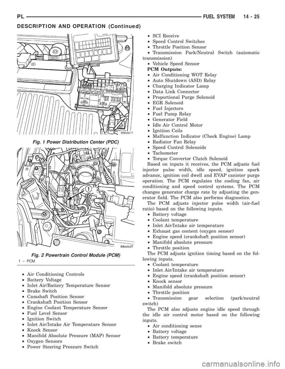
Fig. 1 Power Distribution Center (PDC)
Fig. 2 Powertrain Control Module (PCM)
1 ± PCM
PLFUEL SYSTEM 14 - 25
DESCRIPTION AND OPERATION (Continued)
Page 847 of 1285
²Coolant temperature
²Engine speed (crankshaft position sensor)
²Engine run time
²Manifold absolute pressure
²Power steering pressure switch
²Throttle position
²Transmission gear selection (park/neutral
switch)
²Vehicle distance (speed)
The Auto Shutdown (ASD) and fuel pump relays
are mounted externally, but turned on and off by the
PCM.
The crankshaft position sensor signal is sent to the
PCM. If the PCM does not receive the signal within
approximately one second of engine cranking, it deac-
tivates the ASD relay and fuel pump relay. When
these relays deactivate, power is shut off from the
fuel injectors, ignition coils, heating element in the
oxygen sensors and the fuel pump.
The PCM contains a voltage converter that
changes battery voltage to a regulated 8 volts direct
current to power the camshaft position sensor, crank-
shaft position sensor and vehicle speed sensor. The
PCM also provides a 5 volt direct current supply for
the manifold absolute pressure sensor and throttle
position sensor.
PCM GROUND
OPERATION
Ground is provided through multiple pins of the
PCM connector. Depending on the vehicle there may
be as many as three different ground pins. There are
power grounds and sensor grounds.
The power grounds are used to control the ground
side of any relay, solenoid, ignition coil or injector.
The signal ground is used for any input that uses
sensor return for ground, and the ground side of any
internal processing component.
The SBEC III case is shielded to prevent RFI and
EMI. The PCM case is grounded and must be firmly
attached to a good, clean body ground.
Internally all grounds are connected together, how-
ever there is noise suppression on the sensor ground.
For EMI and RFI protection the case is also
grounded separately from the ground pins.
5 VOLT SUPPLYÐPCM OUTPUT
OPERATION
The PCM supplies 5 volts to the following sensors:
²A/C pressure transducer
²Engine coolant temperature sensor
²Manifold absolute pressure sensor
²Throttle position sensor
²Linear EGR solenoid
8-VOLT SUPPLYÐPCM OUTPUT
OPERATION
The PCM supplies 8 volts to the crankshaft posi-
tion sensor, camshaft position sensor.
FUEL CORRECTION or ADAPTIVE MEMORIES
DESCRIPTION
In Open Loop, the PCM changes pulse width with-
out feedback from the O2 Sensors. Once the engine
warms up to approximately 30 to 35É F, the PCM
goes into closed loopShort Term Correctionand
utilitzes feedback from the O2 Sensors. Closed loop
Long Term Adaptive Memoryis maintained above
170É to 190É F unless the PCM senses wide open
throttle. At that time the PCM returns to Open Loop
operation.
OPERATION
Short Term
The first fuel correction program that begins func-
tioning is the short term fuel correction. This system
corrects fuel delivery in direct proportion to the read-
ings from the Upstream O2 Sensor.
The PCM monitors the air/fuel ratio by using the
input voltage from the O2 Sensor. When the voltage
reaches its preset high or low limit, the PCM begins
to add or remove fuel until the sensor reaches its
switch point. The short term corrections then begin.
The PCM makes a series of quick changes in the
injector pulse-width until the O2 Sensor reaches its
opposite preset limit or switch point. The process
then repeats itself in the opposite direction.
Short term fuel correction will keep increasing or
decreasing injector pulse-width based upon the
upstream O2 Sensor input. The maximum range of
authority for short term memory is 25% (+/-) of base
pulse-width.
Long Term
The second fuel correction program is the long
term adaptive memory. In order to maintain correct
emission throughout all operating ranges of the
engine, a cell structure based on engine rpm and load
(MAP) is used.
There are up to 16 cells. Two cells are used only
during idle, based upon TPS and Park/Neutral
switch inputs. There may be two other cells used for
deceleration, based on TPS, engine rpm, and vehicle
speed. The other twelve cells represent a manifold
pressure and an rpm range. Six of the cells are high
rpm and the other six are low rpm. Each of these
cells is a specific MAP voltage range.
14 - 26 FUEL SYSTEMPL
DESCRIPTION AND OPERATION (Continued)