2000 DODGE NEON oil pan
[x] Cancel search: oil panPage 249 of 1285
DESCRIPTION AND OPERATION
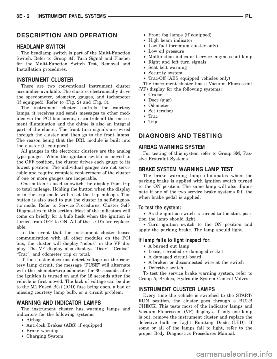
HEADLAMP SWITCH
The headlamp switch is part of the Multi-Function
Switch. Refer to Group 8J, Turn Signal and Flasher
for the Multi-Function Switch Test, Removal and
Installation procedures.
INSTRUMENT CLUSTER
There are two conventional instrument cluster
assemblies available. The clusters electronically drive
the speedometer, odometer, gauges, and tachometer
(if equipped). Refer to (Fig. 2) and (Fig. 3).
The instrument cluster controls the courtesy
lamps, it receives and sends messages to other mod-
ules via the PCI bus circuit, it controls all the instru-
ment illumination and the chime is also an integral
part of the cluster. The front turn signals are wired
through the cluster and then go to the front lamps.
The reason being that the DRL module is built into
the cluster (if equipped).
All gauges in the electronic clusters are the analog
type gauges. When the ignition switch is moved to
the OFF position, the cluster drives each gauge to its
lowest position. The individual gauges are not servi-
cable and require complete replacement of the cluster
if one or more gauges are inoperable.
One button is used to switch the display from trip
to total mileage. Holding the button when the display
is in the trip mode will reset the trip mileage. This
button is also used to put the cluster in self-diagnos-
tic mode. Refer to Service Procedures, Cluster Self-
Diagnostics in this section. Most of the indicators will
come on briefly for a bulb heck when the ignition is
turned from OFF to ON. All of the LED's are replace-
able.
In the event that the instrument cluster looses
communication with all other modules on the PCI
bus, the cluster will display ªnobusº in the VF dis-
play. The VF display also displays ªDoorº, ªCruiseº,
ªTracº, and odometer trip or total.
If the cluster does not detect voltage on the cour-
tesy lamp circuit, the message ªFUSEº will alternate
with the odometer/trip odometer for 30 seconds after
the ignition is turned on and for 15 seconds after the
vehicle is first moved. The lack of voltage can be due
to the M1 Fused B(+) (IOD) fuse being open, a bad or
missing courtesy lamp bulb, or a circuit problem.
WARNING AND INDICATOR LAMPS
The instrument cluster has warning lamps and
indicators for the following systems:
²Airbag
²Anti-lock Brakes (ABS) if equipped
²Brake warning
²Charging System²Front fog lamps (if equipped)
²High beam indicator
²Low fuel (premium cluster only)
²Low oil pressure
²Malfunction indicator (service engine soon) lamp
²Right and left turn signals
²Seat belt warning
²Security system
²Trac-Off (ABS equipped vehicles only)
The instrument cluster has a Vacuum Fluorescent
(VF) display for the following systems:
²Cruise
²Door (ajar)
²Odometer
²Set (cruise)
²Trac
²Trip
DIAGNOSIS AND TESTING
AIRBAG WARNING SYSTEM
For testing of this system refer to Group 8M, Pas-
sive Restraint Systems.
BRAKE SYSTEM WARNING LAMP TEST
The brake warning lamp illuminates when the
parking brake is applied with ignition switch turned
to the ON position. The same lamp will also illumi-
nate if one of the two service brake systems fail the
when brake pedal is applied.
To test the system:
²As the ignition switch is turned to the start posi-
tion the lamp should light.
²Turn ignition switch to the ON position and
apply the parking brake. The lamp should light.
If lamp fails to light inspect for:
²A burned out lamp
²Loose, corroded or damaged socket
²A damaged circuit board
²A broken or disconnected wire at the switch
²Defective switch
To test the service brake warning system, refer to
Group 5, Brakes, Hydraulic System Control Valves.
INSTRUMENT CLUSTER LAMPS
Every time the vehicle is switched to the START/
RUN position, the cluster goes through a BULB
CHECK. This tests most of the indicator lamps and
Vacuum Fluorescent (VF) displays. If only one lamp
is out, remove the instrument cluster and replace the
defective bulb or Light Emitting Diode (LED). If
some or all of the lamps fail to light, refer to the
proper Body Diagnostics Procedures Manual.
8E - 2 INSTRUMENT PANEL SYSTEMSPL
Page 250 of 1285
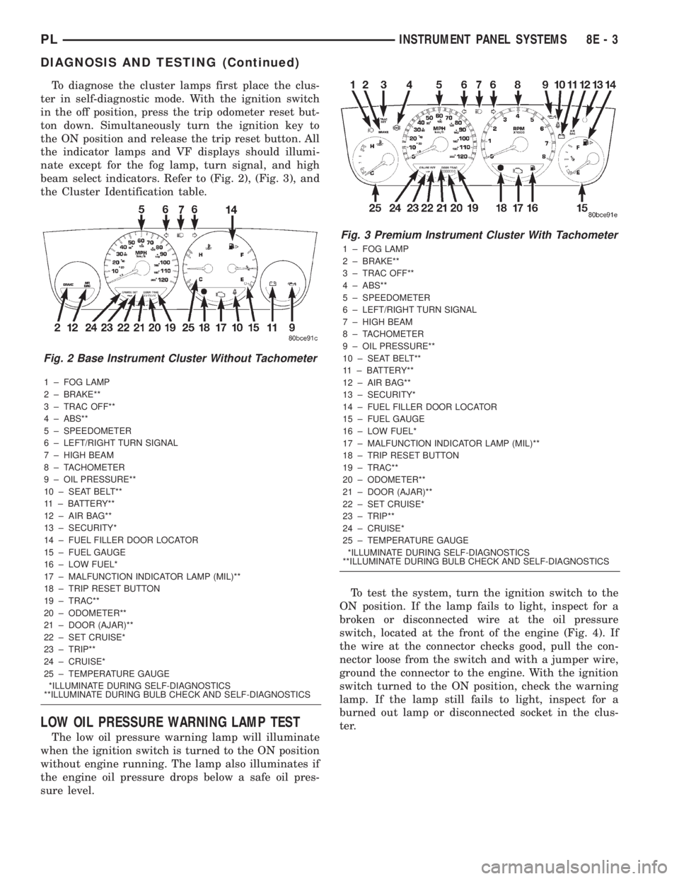
To diagnose the cluster lamps first place the clus-
ter in self-diagnostic mode. With the ignition switch
in the off position, press the trip odometer reset but-
ton down. Simultaneously turn the ignition key to
the ON position and release the trip reset button. All
the indicator lamps and VF displays should illumi-
nate except for the fog lamp, turn signal, and high
beam select indicators. Refer to (Fig. 2), (Fig. 3), and
the Cluster Identification table.
1 ± FOG LAMP
2 ± BRAKE**
3 ± TRAC OFF**
4 ± ABS**
5 ± SPEEDOMETER
6 ± LEFT/RIGHT TURN SIGNAL
7 ± HIGH BEAM
8 ± TACHOMETER
9 ± OIL PRESSURE**
10 ± SEAT BELT**
11 ± BATTERY**
12 ± AIR BAG**
13 ± SECURITY*
14 ± FUEL FILLER DOOR LOCATOR
15 ± FUEL GAUGE
16 ± LOW FUEL*
17 ± MALFUNCTION INDICATOR LAMP (MIL)**
18 ± TRIP RESET BUTTON
19 ± TRAC**
20 ± ODOMETER**
21 ± DOOR (AJAR)**
22 ± SET CRUISE*
23 ± TRIP**
24 ± CRUISE*
25 ± TEMPERATURE GAUGE
*ILLUMINATE DURING SELF-DIAGNOSTICS
**ILLUMINATE DURING BULB CHECK AND SELF-DIAGNOSTICS
LOW OIL PRESSURE WARNING LAMP TEST
The low oil pressure warning lamp will illuminate
when the ignition switch is turned to the ON position
without engine running. The lamp also illuminates if
the engine oil pressure drops below a safe oil pres-
sure level.To test the system, turn the ignition switch to the
ON position. If the lamp fails to light, inspect for a
broken or disconnected wire at the oil pressure
switch, located at the front of the engine (Fig. 4). If
the wire at the connector checks good, pull the con-
nector loose from the switch and with a jumper wire,
ground the connector to the engine. With the ignition
switch turned to the ON position, check the warning
lamp. If the lamp still fails to light, inspect for a
burned out lamp or disconnected socket in the clus-
ter.
Fig. 2 Base Instrument Cluster Without Tachometer
Fig. 3 Premium Instrument Cluster With Tachometer
1 ± FOG LAMP
2 ± BRAKE**
3 ± TRAC OFF**
4 ± ABS**
5 ± SPEEDOMETER
6 ± LEFT/RIGHT TURN SIGNAL
7 ± HIGH BEAM
8 ± TACHOMETER
9 ± OIL PRESSURE**
10 ± SEAT BELT**
11 ± BATTERY**
12 ± AIR BAG**
13 ± SECURITY*
14 ± FUEL FILLER DOOR LOCATOR
15 ± FUEL GAUGE
16 ± LOW FUEL*
17 ± MALFUNCTION INDICATOR LAMP (MIL)**
18 ± TRIP RESET BUTTON
19 ± TRAC**
20 ± ODOMETER**
21 ± DOOR (AJAR)**
22 ± SET CRUISE*
23 ± TRIP**
24 ± CRUISE*
25 ± TEMPERATURE GAUGE
*ILLUMINATE DURING SELF-DIAGNOSTICS
**ILLUMINATE DURING BULB CHECK AND SELF-DIAGNOSTICS
PLINSTRUMENT PANEL SYSTEMS 8E - 3
DIAGNOSIS AND TESTING (Continued)
Page 251 of 1285
MULTIPLE/INDIVIDUAL GAUGES INOPERATIVE
Test speedometer, tachometer and other gauges for
malfunction:
(1) Remove the cluster. Refer to Cluster Removal
and Installation.
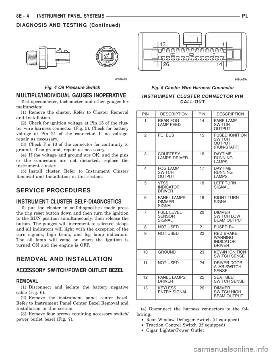
(2) Check for ignition voltage at Pin 15 of the clus-
ter wire harness connector (Fig. 5). Check for battery
voltage at Pin 21 of the connector. If no voltage,
repair as necessary.
(3) Check Pin 10 of the connector for continuity to
ground. If no ground, repair as necessary.
(4) If the voltage and ground are OK, and the pins
or the connectors are not distorted, replace the
instrument cluster.
(5) Install cluster. Refer to Instrument Cluster
Removal and Installation in this section.
SERVICE PROCEDURES
INSTRUMENT CLUSTER SELF-DIAGNOSTICS
To put the cluster in self-diagnostics mode press
the trip reset button down and then turn the ignition
to the RUN position simultaneously, then release the
button. The gauges will increment to selected stoops
and all indicators will light with the exception of the
turn signals, high beam, and fog lamp indicators.
The oil lamp will come on when the ignition is
turned ON and the engine is OFF.
REMOVAL AND INSTALLATION
ACCESSORY SWITCH/POWER OUTLET BEZEL
REMOVAL
(1) Disconnect and isolate the battery negative
cable (Fig. 6).
(2) Remove the instrument panel center bezel.
Refer to Instrument Panel Center Bezel Removal and
Installation in this section.
(3) Remove four screws retaining accessory switch/
power outlet bezel (Fig. 7).(4) Disconnect the harness connectors to the fol-
lowing:
²Rear Window Defogger Switch (if equipped)
²Traction Control Switch (if equipped)
²Cigar Lighter/Power Outlet
Fig. 5 Cluster Wire Harness Connector
INSTRUMENT CLUSTER CONNECTOR PIN
CALL-OUT
PIN DESCRIPTION PIN DESCRIPTION
1 REAR FOG
LAMP FEED14 PARK LAMP
SWITCH
OUTPUT
2 PCI BUS 15 FUSED IGNITION
SWITCH
OUTPUT
(RUN-START)
3 COURTESY
LAMPS DRIVER16 DAYTIME
RUNNING
LAMPS
4 FOG LAMP
SWITCH
OUTPUT17 DAYTIME
RUNNING
LAMPS
5 VTSS
INDICATOR
DRIVER18 LEFT TURN
SIGNAL
6 PANEL LAMPS
DIMMER
SIGNAL19 RIGHT TURN
SIGNAL
7 FUEL LEVEL
SENSOR
SIGNAL20 DIMMER
SWITCH LOW
BEAM OUTPUT
8 NOT USED 21 FUSED B+
9 NOT USED 22 RED BRAKE
WARNING
INDICATOR
DRIVER
10 GROUND 23 KEY-IN IGNITION
SWITCH SENSE
11 NOT USED 24 DRIVER DOOR
AJAR SWITCH
SENSE
12 PANEL LAMPS
DRIVER25 SEAT BELT
SWITCH SENSE
13 KEYLESS
ENTRY SIGNAL26 DIMMER
SWITCH HIGH
BEAM OUTPUT
Fig. 4 Oil Pressure Switch
8E - 4 INSTRUMENT PANEL SYSTEMSPL
DIAGNOSIS AND TESTING (Continued)
Page 308 of 1285
LAMPS
TABLE OF CONTENTS
page page
LAMP DIAGNOSIS......................... 1
HEADLAMP ALIGNMENT.................... 4
LAMP BULB SERVICE...................... 7LAMP SERVICE........................... 12
LAMP SYSTEMS.......................... 16
BULB APPLICATION....................... 17
LAMP DIAGNOSIS
TABLE OF CONTENTS
page page
DESCRIPTION AND OPERATION
DIAGNOSTIC PROCEDURES................1
SAFETY PRECAUTIONS....................1
DAYTIME RUNNING LAMP MODULE...........1DIAGNOSIS AND TESTING
HEADLAMP DIAGNOSIS....................1
FOG LAMP..............................3
DESCRIPTION AND OPERATION
DIAGNOSTIC PROCEDURES
When a vehicle experiences problems with the
headlamp system, verify the condition of the battery
connections, fuses, charging system, headlamp bulbs,
wire connectors, relay, high beam switch, dimmer
switch, and headlamp switch. Refer to Group 8W,
Wiring Diagrams for component locations and circuit
information.
SAFETY PRECAUTIONS
WARNING: EYE PROTECTION SHOULD BE USED
WHEN SERVICING GLASS COMPONENTS. PER-
SONAL INJURY CAN RESULT.
CAUTION: Do not touch the glass of halogen bulbs
with fingers or other possibly oily surface, reduced
bulb life will result.
Do not use bulbs with higher candle power than
indicated in the Bulb Application table at the end of
this group. Damage to lamp and/or Daytime Run-
ning Lamp Module can result.
Do not use fuses, circuit breakers or relays hav-
ing greater amperage value than indicated on the
fuse panel or in the Owners Manual.When it is necessary to remove components to ser-
vice another, it should not be necessary to apply
excessive force or bend a component to remove it.
Before damaging a trim component, verify hidden
fasteners or captured edges are not holding the com-
ponent in place.
DAYTIME RUNNING LAMP MODULE
PL vehicles built for use in Canada are equipped
with a Daytime Running Lamp (DRL) system. Turn
signal lamp circuitry always comes from the multi-
function switch, and goes to the cluster connector,
into the cluster, then back out to the front turn sig-
nal switch lamps. The Canadian cluster provides
steady illumination of the front turn signal when the
ignition switch is in the ON position. The DRL func-
tion may be inhibited by activating the turn signals,
the hazard flashers, the headlamp switch, or park
brake.
DIAGNOSIS AND TESTING
HEADLAMP DIAGNOSIS
Always begin any diagnosis by testing all of the
fuses and circuit breakers in the system. Refer to
Group 8W, Wiring Diagrams.
Conventional and halogen headlamps are inter-
changeable. It is recommended that they not be
intermixed on a given vehicle.
PLLAMPS 8L - 1
Page 324 of 1285
BULB APPLICATION
TABLE OF CONTENTS
page page
SPECIFICATIONS
EXTERIOR LAMPS........................17INTERIOR LAMPS........................17
SPECIFICATIONS
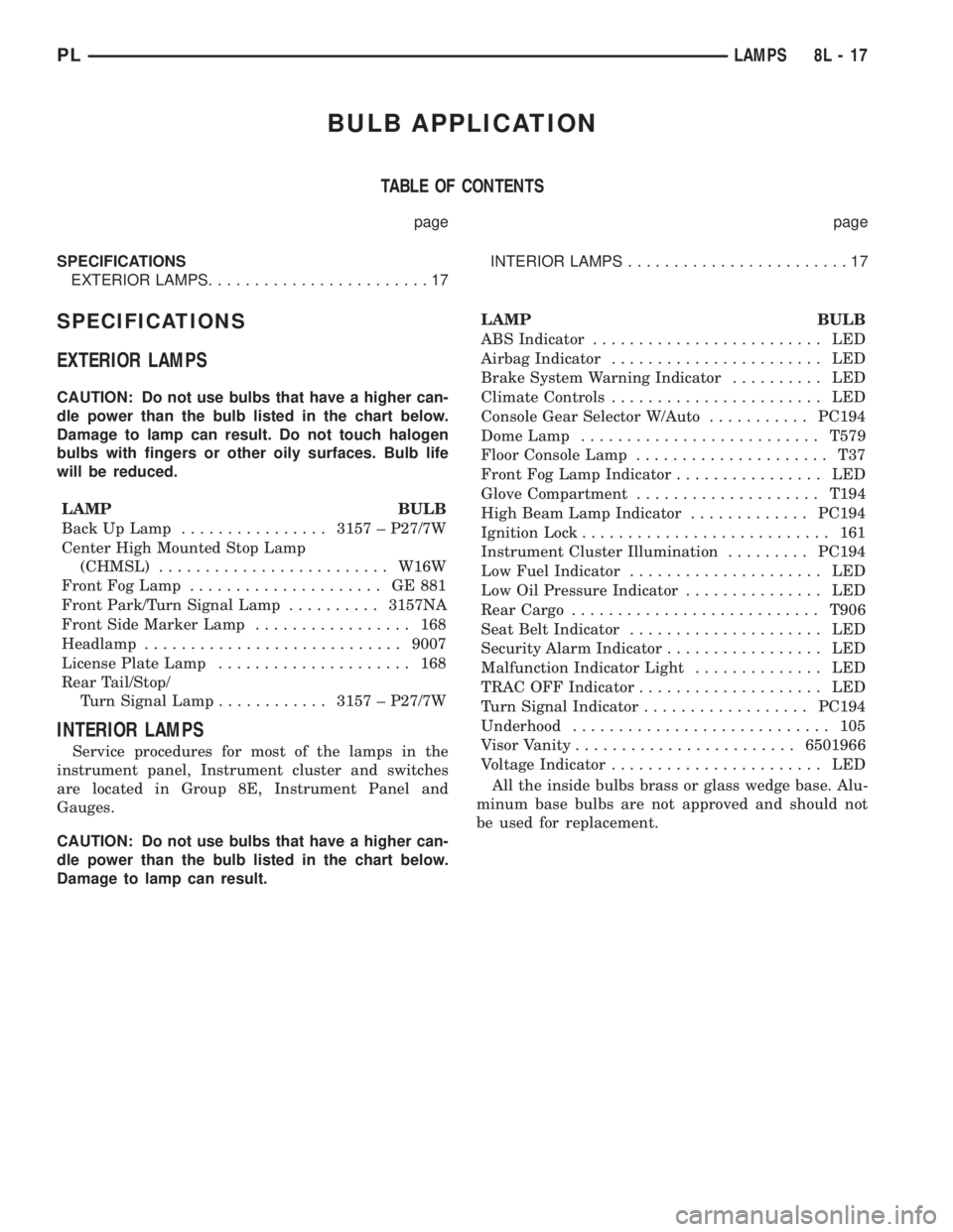
EXTERIOR LAMPS
CAUTION: Do not use bulbs that have a higher can-
dle power than the bulb listed in the chart below.
Damage to lamp can result. Do not touch halogen
bulbs with fingers or other oily surfaces. Bulb life
will be reduced.
LAMP BULB
Back Up Lamp................3157 ± P27/7W
Center High Mounted Stop Lamp
(CHMSL).........................W16W
Front Fog Lamp..................... GE881
Front Park/Turn Signal Lamp..........3157NA
Front Side Marker Lamp................. 168
Headlamp............................9007
License Plate Lamp..................... 168
Rear Tail/Stop/
Turn Signal Lamp............3157 ± P27/7W
INTERIOR LAMPS
Service procedures for most of the lamps in the
instrument panel, Instrument cluster and switches
are located in Group 8E, Instrument Panel and
Gauges.
CAUTION: Do not use bulbs that have a higher can-
dle power than the bulb listed in the chart below.
Damage to lamp can result.LAMP BULB
ABS Indicator......................... LED
Airbag Indicator....................... LED
Brake System Warning Indicator.......... LED
Climate Controls....................... LED
Console Gear Selector W/Auto...........PC194
Dome Lamp..........................T579
Floor Console Lamp..................... T37
Front Fog Lamp Indicator................ LED
Glove Compartment....................T194
High Beam Lamp Indicator.............PC194
Ignition Lock........................... 161
Instrument Cluster Illumination.........PC194
Low Fuel Indicator..................... LED
Low Oil Pressure Indicator............... LED
Rear Cargo...........................T906
Seat Belt Indicator..................... LED
Security Alarm Indicator................. LED
Malfunction Indicator Light.............. LED
TRAC OFF Indicator.................... LED
Turn Signal Indicator..................PC194
Underhood............................ 105
Visor Vanity........................6501966
Voltage Indicator....................... LED
All the inside bulbs brass or glass wedge base. Alu-
minum base bulbs are not approved and should not
be used for replacement.
PLLAMPS 8L - 17
Page 331 of 1285
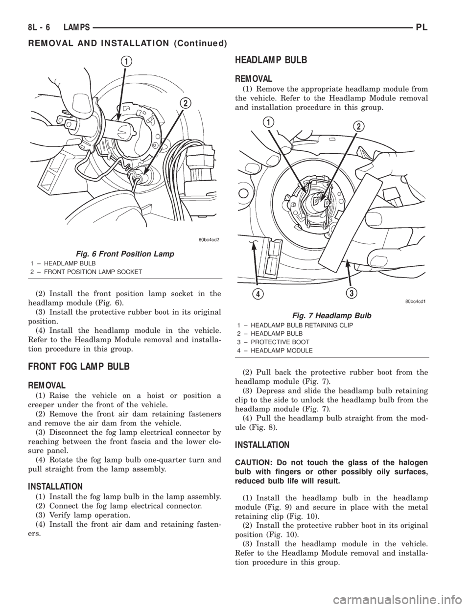
(2) Install the front position lamp socket in the
headlamp module (Fig. 6).
(3) Install the protective rubber boot in its original
position.
(4) Install the headlamp module in the vehicle.
Refer to the Headlamp Module removal and installa-
tion procedure in this group.
FRONT FOG LAMP BULB
REMOVAL
(1) Raise the vehicle on a hoist or position a
creeper under the front of the vehicle.
(2) Remove the front air dam retaining fasteners
and remove the air dam from the vehicle.
(3) Disconnect the fog lamp electrical connector by
reaching between the front fascia and the lower clo-
sure panel.
(4) Rotate the fog lamp bulb one-quarter turn and
pull straight from the lamp assembly.
INSTALLATION
(1) Install the fog lamp bulb in the lamp assembly.
(2) Connect the fog lamp electrical connector.
(3) Verify lamp operation.
(4) Install the front air dam and retaining fasten-
ers.
HEADLAMP BULB
REMOVAL
(1) Remove the appropriate headlamp module from
the vehicle. Refer to the Headlamp Module removal
and installation procedure in this group.
(2) Pull back the protective rubber boot from the
headlamp module (Fig. 7).
(3) Depress and slide the headlamp bulb retaining
clip to the side to unlock the headlamp bulb from the
headlamp module (Fig. 7).
(4) Pull the headlamp bulb straight from the mod-
ule (Fig. 8).
INSTALLATION
CAUTION: Do not touch the glass of the halogen
bulb with fingers or other possibly oily surfaces,
reduced bulb life will result.
(1) Install the headlamp bulb in the headlamp
module (Fig. 9) and secure in place with the metal
retaining clip (Fig. 10).
(2) Install the protective rubber boot in its original
position (Fig. 10).
(3) Install the headlamp module in the vehicle.
Refer to the Headlamp Module removal and installa-
tion procedure in this group.
Fig. 6 Front Position Lamp
1 ± HEADLAMP BULB
2 ± FRONT POSITION LAMP SOCKET
Fig. 7 Headlamp Bulb
1 ± HEADLAMP BULB RETAINING CLIP
2 ± HEADLAMP BULB
3 ± PROTECTIVE BOOT
4 ± HEADLAMP MODULE
8L - 6 LAMPSPL
REMOVAL AND INSTALLATION (Continued)
Page 410 of 1285
8W-02 COMPONENT INDEX
Component Page
A/C Compressor Clutch Relay............8W-42
A/C Compressor Clutch.................8W-42
A/C Cycling Switch....................8W-42
A/C Heater Blower Motor...............8W-42
A/C Heater Control....................8W-42
A/C Pressure Switches..................8W-42
Airbag Control Module.................8W-43
Airbags.............................8W-43
Antenna.............................8W-47
Automatic Shut Down Relay.............8W-30
Back-Up Lamp Switch..................8W-51
Back-Up Lamps.......................8W-51
Battery.............................8W-20
Blower Motor Resistor Block.............8W-42
Brake Lamp Switch....................8W-30
Brake Shift Interlock Solenoid...........8W-30
Brake Warning Indicator Switch..........8W-40
Camshaft Position Sensor...............8W-30
Cargo Lamp..........................8W-44
Center High Mounted Stop Lamp.........8W-51
Center Stack Lamp....................8W-44
Cigar Lighter/Power Outlet..............8W-41
Circuit Breakers (FB)..................8W-11
City Lamps..........................8W-50
Clockspring.....................8W-33, 41, 43
Clutch Interlock Switch.................8W-30
Combination Flasher...................8W-52
Controller Anti-Lock Brake..............8W-35
Crankshaft Position Sensor..............8W-30
Data Link Connector...................8W-30
Decklid Release Switch.................8W-44
Decklid Solenoid......................8W-61
Diode No. 1..........................8W-42
Dome Lamp..........................8W-44
Dome Lamp/Intrusion Sensor............8W-44
Door Ajar Switches....................8W-40
Door Lock Motors.....................8W-61
Engine Coolant Temperature Sensor.......8W-30
Engine Oil Pressure Switch..............8W-30
Engine Starter Motor Relay.............8W-21
Engine Starter Motor..................8W-21
Fog Lamps........................8W-50, 51
Front Fog Lamp Switch.................8W-50
Fuel Injectors........................8W-30
Fuel Pump Module....................8W-30
Fuel Pump Relay......................8W-30
Fuel Tank...........................8W-30
Fuses (FB)...........................8W-11
Fuses (PDC).........................8W-10
Fuse Block...........................8W-11
Fusible Link A11...................8W-20, 21
Grounds.............................8W-15Component Page
Generator...........................8W-20
Glove Box Lamp/Switch.................8W-44
Headlamp Beam Select..............8W-40, 50
Headlamp Leveling Motors..............8W-50
Headlamp Leveling Switch Illumination....8W-50
Headlamp Leveling Switch..............8W-50
Headlamp Switch...................8W-50, 51
Headlamps..........................8W-50
Horns..............................8W-41
Horn Relay..........................8W-41
Horn Switch.........................8W-41
Hood Ajar Switch......................8W-39
Idle Air Control Motor..................8W-30
Ignition Coil.........................8W-30
Ignition Switch.......................8W-10
Indicators...........................8W-40
Indicator Drivers......................8W-40
Inlet Air Temperature Sensor............8W-30
Instrument Cluster....................8W-40
Instrument Panel Drivers...............8W-40
Knock Sensor.........................8W-30
Leak Detection Pump..................8W-30
License Lamps........................8W-51
Manifold Absolute Pressure Sensor........8W-30
Map/Reading Lamps...................8W-44
Multi- Function Switch.........8W-40, 50, 51, 52
Noise Suppressor......................8W-30
Oxygen Sensors.......................8W-30
Park Brake Switch....................8W-40
Park/Neutral Position Switch............8W-51
Park/Turn Signal Lamps................8W-52
Power Distribution Center...............8W-10
Power Mirror Switch...................8W-62
Power Steering Pressure Switch..........8W-30
Powertrain Control Module..............8W-30
PRNDL Lamp........................8W-44
Proportional Evap/Purge Solenoid.........8W-30
Radiator Fan Motor....................8W-42
Radiator Fan Relay....................8W-42
Radio...............................8W-47
Rear Window Defogger Switch...........8W-48
Rear Window Defogger.................8W-48
Remote Keyless Entry Module............8W-39
Repeater Lamps......................8W-52
Seat Belt Switch......................8W-40
Sentry Key Immobilizer Module..........8W-39
Side Marker Lamps....................8W-50
Siren...............................8W-39
Speakers............................8W-47
Splice Information.....................8W-70
Sunroof Control Module................8W-64
Sunroof Motor........................8W-64
PL8W - 02 COMPONENT INDEX 8W - 02 - 1
Page 412 of 1285
8W-10 POWER DISTRIBUTION
Component Page
A/C Compressor Clutch Relay........8W-10-7, 16
Automatic Shut Down Relay...........8W-10-16
Battery............................8W-10-7
Brake Lamp Switch................8W-10-7, 18
Cargo Lamp.......................8W-10-12
Center High Mounted Stop Lamp.......8W-10-18
Cigar Lighter/Power Outlet............8W-10-8
Circuit Breaker No. 1 (FB).............8W-10-9
Circuit Breaker No. 2 (FB).............8W-10-9
Combination Flasher.................8W-10-13
Controller Anti-Lock Brake.......8W-10-7, 11, 18
Data Link Connector.................8W-10-16
Dome Lamp.......................8W-10-12
Dome Lamp/Intrusion Sensor..........8W-10-12
Engine Starter Motor.................8W-10-8
Engine Starter Motor Relay........8W-10-7, 8, 10
Front Fog Lamp Switch..............8W-10-14
Fuel Injector No. 1..................8W-10-17
Fuel Injector No. 2..................8W-10-17
Fuel Injector No. 3..................8W-10-17
Fuel Injector No. 4..................8W-10-17
Fuel Pump Module..................8W-10-16
Fuel Pump Relay...................8W-10-16
Fuse 1 (FB)........................8W-10-10
Fuse 2 (FB)........................8W-10-10
Fuse 5 (PDC).......................8W-10-7
Fuse 6 (FB).........................8W-10-9
Fuse 6 (PDC).....................8W-10-7, 11
Fuse 7 (FB).........................8W-10-9
Fuse 8 (FB).........................8W-10-9
Fuse 8 (PDC).....................8W-10-7, 11
Fuse 9 (FB)........................8W-10-10
Fuse 9 (PDC)......................8W-10-7, 8
Fuse 10 (FB).......................8W-10-10
Fuse 10 (PDC)....................8W-10-7, 11
Fuse 11 (FB).......................8W-10-10
Fuse 12 (FB).......................8W-10-10
Fuse 13 (PDC)....................8W-10-7, 12
Fuse 14 (FB)........................8W-10-9
Fuse 14 (PDC).....................8W-10-7, 8
Fuse 15 (FB)........................8W-10-9
Fuse 15 (PDC)....................8W-10-7, 13
Fuse 16 (FB)........................8W-10-9Component Page
Fuse 18 (PDC)....................8W-10-7, 13
Fuse 20 (FB).......................8W-10-11
Fuse 20 (PDC)....................8W-10-7, 14
Fuse 21 (PDC)....................8W-10-7, 16
Fuse 22 (PDC)....................8W-10-7, 16
Fuse 23 (PDC)....................8W-10-7, 18
Fuse Block....................8W-10-9, 10, 11
Generator.........................8W-10-17
Glove Box Lamp/Switch..............8W-10-12
Headlamp Switch...................8W-10-14
High Note Horn....................8W-10-13
Horn Relay......................8W-10-7, 13
Ignition Coil.......................8W-10-17
Ignition Switch................8W-10-7, 8, 9, 10
Instrument Cluster.............8W-10-8, 12, 14
Instrument Panel Drivers.............8W-10-14
Left Front Fog Lamp..............8W-10-14, 15
Left Tail/Stop Lamp.................8W-10-18
Left Tail/Stop/Turn Signal Lamp........8W-10-19
Left Visor/Vanity Lamp...............8W-10-12
Low Note Horn.....................8W-10-13
Map/Reading Lamps.................8W-10-12
Multi-Function Switch......8W-10-7, 13, 14, 15, 19
Noise Suppressor...................8W-10-17
Oxygen Sensor 1/1 Upstream..........8W-10-17
Oxygen Sensor 1/2 Downstream........8W-10-17
Power Distribution Center.....8W-10-2, 3, 4, 7, 8,
9, 11, 12, 13, 14, 16, 18
Powertrain Control Module.........8W-10-16, 17
Radiator Fan Motor.................8W-10-11
Radiator Fan Relay................8W-10-7, 11
Radio.............................8W-10-12
Rear Window Defogger...............8W-10-11
Rear Window Defogger Switch.........8W-10-11
Remote Keyless Entry Module.........8W-10-12
Right Front Fog Lamp...............8W-10-15
Right Rear Fog Lamp................8W-10-14
Right Tail/Stop Lamp................8W-10-18
Right Tail/Stop/Turn Signal Lamp......8W-10-19
Right Visor/Vanity Lamp..............8W-10-12
Sentry Key Immobilizer Module........8W-10-12
Siren.............................8W-10-12
Underhood Lamp...................8W-10-12
PL8W - 10 POWER DISTRIBUTION 8W - 10 - 1