2000 DODGE NEON instrument cluster
[x] Cancel search: instrument clusterPage 699 of 1285
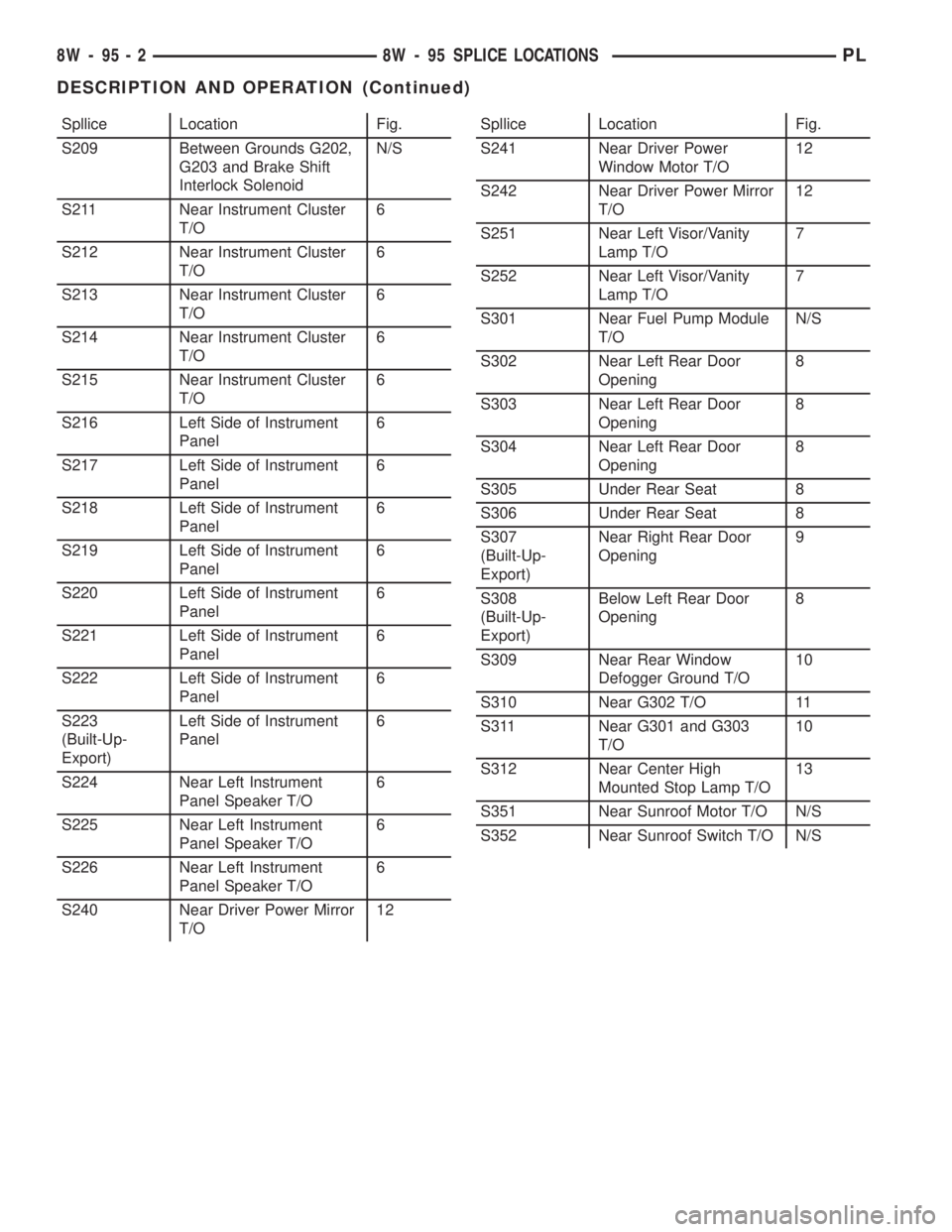
Spllice Location Fig.
S209 Between Grounds G202,
G203 and Brake Shift
Interlock SolenoidN/S
S211 Near Instrument Cluster
T/O6
S212 Near Instrument Cluster
T/O6
S213 Near Instrument Cluster
T/O6
S214 Near Instrument Cluster
T/O6
S215 Near Instrument Cluster
T/O6
S216 Left Side of Instrument
Panel6
S217 Left Side of Instrument
Panel6
S218 Left Side of Instrument
Panel6
S219 Left Side of Instrument
Panel6
S220 Left Side of Instrument
Panel6
S221 Left Side of Instrument
Panel6
S222 Left Side of Instrument
Panel6
S223
(Built-Up-
Export)Left Side of Instrument
Panel6
S224 Near Left Instrument
Panel Speaker T/O6
S225 Near Left Instrument
Panel Speaker T/O6
S226 Near Left Instrument
Panel Speaker T/O6
S240 Near Driver Power Mirror
T/O12Spllice Location Fig.
S241 Near Driver Power
Window Motor T/O12
S242 Near Driver Power Mirror
T/O12
S251 Near Left Visor/Vanity
Lamp T/O7
S252 Near Left Visor/Vanity
Lamp T/O7
S301 Near Fuel Pump Module
T/ON/S
S302 Near Left Rear Door
Opening8
S303 Near Left Rear Door
Opening8
S304 Near Left Rear Door
Opening8
S305 Under Rear Seat 8
S306 Under Rear Seat 8
S307
(Built-Up-
Export)Near Right Rear Door
Opening9
S308
(Built-Up-
Export)Below Left Rear Door
Opening8
S309 Near Rear Window
Defogger Ground T/O10
S310 Near G302 T/O 11
S311 Near G301 and G303
T/O10
S312 Near Center High
Mounted Stop Lamp T/O13
S351 Near Sunroof Motor T/O N/S
S352 Near Sunroof Switch T/O N/S
8W - 95 - 2 8W - 95 SPLICE LOCATIONSPL
DESCRIPTION AND OPERATION (Continued)
Page 710 of 1285
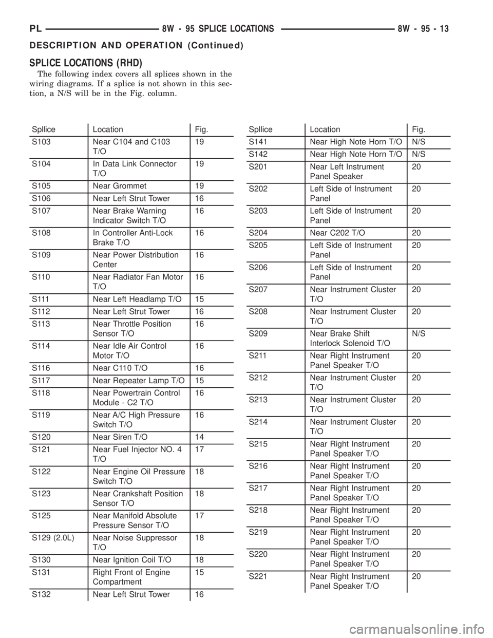
SPLICE LOCATIONS (RHD)
The following index covers all splices shown in the
wiring diagrams. If a splice is not shown in this sec-
tion, a N/S will be in the Fig. column.
Spllice Location Fig.
S103 Near C104 and C103
T/O19
S104 In Data Link Connector
T/O19
S105 Near Grommet 19
S106 Near Left Strut Tower 16
S107 Near Brake Warning
Indicator Switch T/O16
S108 In Controller Anti-Lock
Brake T/O16
S109 Near Power Distribution
Center16
S110 Near Radiator Fan Motor
T/O16
S111 Near Left Headlamp T/O 15
S112 Near Left Strut Tower 16
S113 Near Throttle Position
Sensor T/O16
S114 Near Idle Air Control
Motor T/O16
S116 Near C110 T/O 16
S117 Near Repeater Lamp T/O 15
S118 Near Powertrain Control
Module - C2 T/O16
S119 Near A/C High Pressure
Switch T/O16
S120 Near Siren T/O 14
S121 Near Fuel Injector NO. 4
T/O17
S122 Near Engine Oil Pressure
Switch T/O18
S123 Near Crankshaft Position
Sensor T/O18
S125 Near Manifold Absolute
Pressure Sensor T/O17
S129 (2.0L) Near Noise Suppressor
T/O18
S130 Near Ignition Coil T/O 18
S131 Right Front of Engine
Compartment15
S132 Near Left Strut Tower 16Spllice Location Fig.
S141 Near High Note Horn T/O N/S
S142 Near High Note Horn T/O N/S
S201 Near Left Instrument
Panel Speaker20
S202 Left Side of Instrument
Panel20
S203 Left Side of Instrument
Panel20
S204 Near C202 T/O 20
S205 Left Side of Instrument
Panel20
S206 Left Side of Instrument
Panel20
S207 Near Instrument Cluster
T/O20
S208 Near Instrument Cluster
T/O20
S209 Near Brake Shift
Interlock Solenoid T/ON/S
S211 Near Right Instrument
Panel Speaker T/O20
S212 Near Instrument Cluster
T/O20
S213 Near Instrument Cluster
T/O20
S214 Near Instrument Cluster
T/O20
S215 Near Right Instrument
Panel Speaker T/O20
S216 Near Right Instrument
Panel Speaker T/O20
S217 Near Right Instrument
Panel Speaker T/O20
S218 Near Right Instrument
Panel Speaker T/O20
S219 Near Right Instrument
Panel Speaker T/O20
S220 Near Right Instrument
Panel Speaker T/O20
S221 Near Right Instrument
Panel Speaker T/O20
PL8W - 95 SPLICE LOCATIONS 8W - 95 - 13
DESCRIPTION AND OPERATION (Continued)
Page 711 of 1285
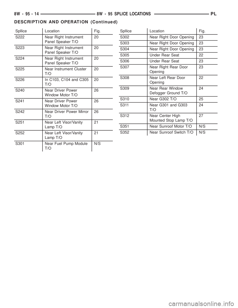
Spllice Location Fig.
S222 Near Right Instrument
Panel Speaker T/O20
S223 Near Right Instrument
Panel Speaker T/O20
S224 Near Right Instrument
Panel Speaker T/O20
S225 Near Instrument Cluster
T/O20
S226 In C103, C104 and C305
T/O20
S240 Near Driver Power
Window Motor T/O26
S241 Near Driver Power
Window Motor T/O26
S242 Near Driver Power Mirror
T/O26
S251 Near Left Visor/Vanity
Lamp T/O21
S252 Near Left Visor/Vanity
Lamp T/O21
S301 Near Fuel Pump Module
T/ON/SSpllice Location Fig.
S302 Near Right Door Opening 23
S303 Near Right Door Opening 23
S304 Near Right Door Opening 23
S305 Under Rear Seat 22
S306 Under Rear Seat 23
S307 Near Right Rear Door
Opening23
S308 Near Left Rear Door
Opening22
S309 Near Rear Window
Defogger Ground T/O24
S310 Near G302 T/O 25
S311 Near G301 and G303
T/O24
S312 Near Center High
Mounted Stop Lamp T/O27
S351 Near Sunroof Motor T/O N/S
S352 Near Sunroof Switch T/O N/S
8W - 95 - 14 8W - 95 SPLICE LOCATIONSPL
DESCRIPTION AND OPERATION (Continued)
Page 825 of 1285
The inlet strainer, fuel pressure regulator and fuel
level sensor are the only serviceable items. If the fuel
pump requires service, replace the fuel pump module.
ELECTRIC FUEL PUMP
DESCRIPTION
The electric fuel pump is located in and is part of
the fuel pump module. It is a positive displacement,
gerotor type, immersible pump with a permanent
magnet electric motor. The fuel pump module is sus-
pended in fuel in the fuel tank.
OPERATION
The pump draws fuel through a strainer and
pushes it through the motor to the outlet. The pump
contains a check valve. The valve, in the pump out-
let, maintains pump pressure during engine off con-
ditions. The fuel pump relay provides voltage to the
fuel pump. The fuel pump has a maximum dead-
headed pressure output of approximately 880 kPa
(130 psi). The regulator adjusts fuel system pressure
to approximately 338 kPa (49 psi).
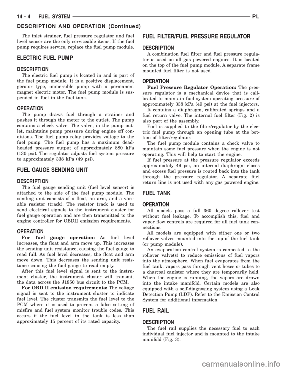
FUEL GAUGE SENDING UNIT
DESCRIPTION
The fuel gauge sending unit (fuel level sensor) is
attached to the side of the fuel pump module. The
sending unit consists of a float, an arm, and a vari-
able resistor (track). The resistor track is used to
send electrical signals to the instrument cluster for
fuel gauge operation and are then transmitted to the
engine controller for OBDII emission requirements.
OPERATION
For fuel gauge operation:As fuel level
increases, the float and arm move up. This increases
the sending unit resistance, causing the fuel gauge to
read full. As fuel level decreases, the float and arm
move down. This decreases the sending unit resis-
tance causing the fuel gauge to read empty.
After this fuel level signal is sent to the instru-
ment cluster, the instrument cluster will transmit
the data across the J1850 bus circuit to the PCM.
For OBD II emission requirements:The voltage
signal is sent to the instrument cluster to indicate
fuel level. The cluster transmits the fuel level to the
PCM where it is used to prevent a false setting of
misfire and fuel system monitor trouble codes. This
occurs if the fuel level in the tank is less than
approximately 15 percent of its rated capacity.
FUEL FILTER/FUEL PRESSURE REGULATOR
DESCRIPTION
A combination fuel filter and fuel pressure regula-
tor is used on all gas powered engines. It is located
on the top of the fuel pump module. A separate frame
mounted fuel filter is not used.
OPERATION
Fuel Pressure Regulator Operation:The pres-
sure regulator is a mechanical device that is cali-
brated to maintain fuel system operating pressure of
approximately 338 kPa (49 psi) at the fuel injectors.
It contains a diaphragm, calibrated springs and a
fuel return valve. The internal fuel filter (Fig. 2) is
also part of the assembly.
Fuel is supplied to the filter/regulator by the elec-
tric fuel pump through an opening tube at the bot-
tom of filter/regulator.
The fuel pump module contains a check valve to
maintain some fuel pressure when the engine is not
operating. This will help to start the engine.
If fuel pressure at the pressure regulator exceeds
approximately 49 psi, an internal diaphragm closes
and excess fuel pressure is routed back into the tank
through the pressure regulator. A separate fuel
return line is not used with any gas powered engine.
FUEL TANK
OPERATION
All models pass a full 360 degree rollover test
without fuel leakage. To accomplish this, fuel and
vapor flow controls are required for all fuel tank con-
nections.
All models are equipped with either one or two
rollover valves mounted into the top of the fuel tank
(or pump module).
An evaporation control system is connected to the
rollover valve(s) to reduce emissions of fuel vapors
into the atmosphere. When fuel evaporates from the
fuel tank, vapors pass through vent hoses or tubes to
a charcoal canister where they are temporarily held.
When the engine is running, the vapors are drawn
into the intake manifold. Certain models are also
equipped with a self-diagnosing system using a Leak
Detection Pump (LDP). Refer to the Emission Control
System for additional information.
FUEL RAIL
DESCRIPTION
The fuel rail supplies the necessary fuel to each
individual fuel injector and is mounted to the intake
manifold (Fig. 3).
14 - 4 FUEL SYSTEMPL
DESCRIPTION AND OPERATION (Continued)
Page 852 of 1285
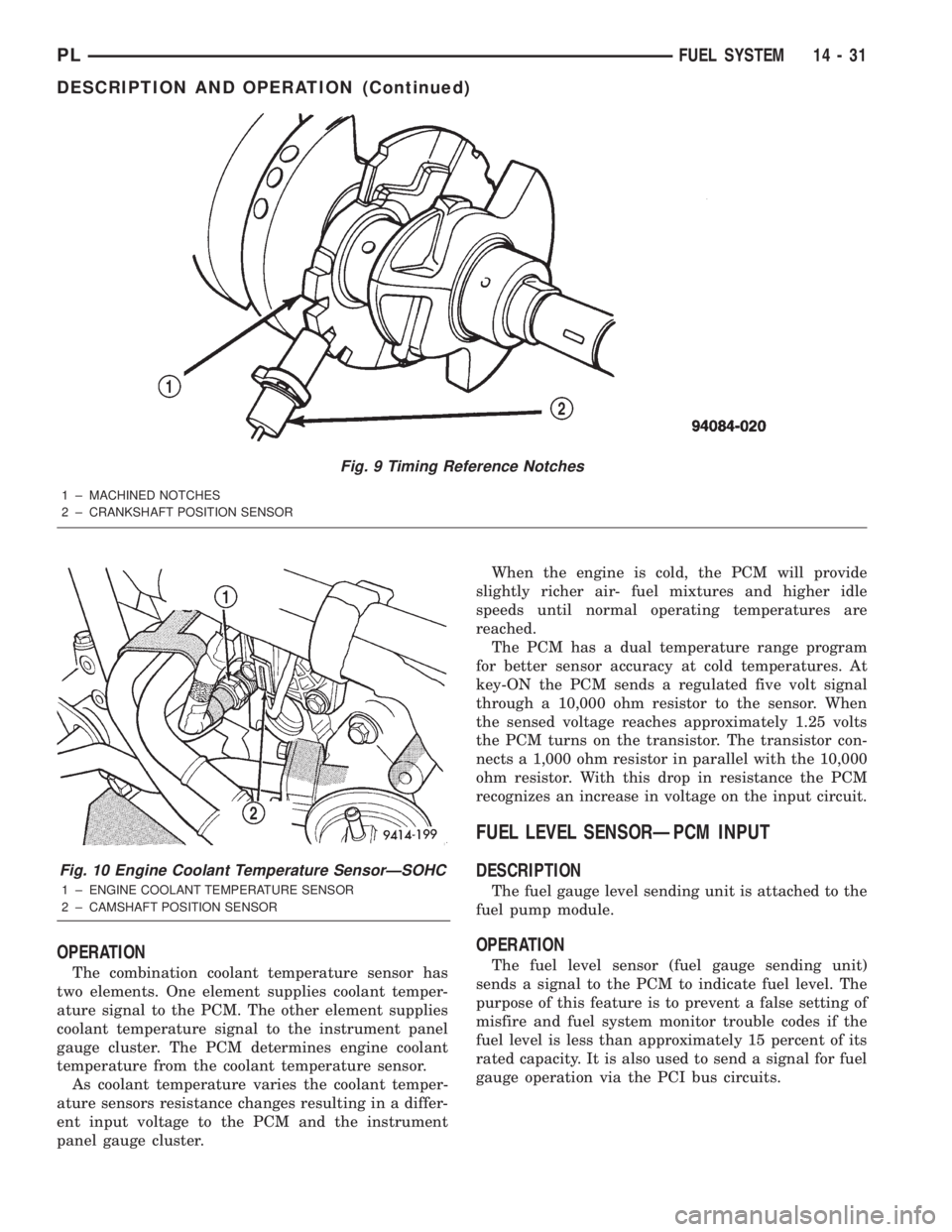
OPERATION
The combination coolant temperature sensor has
two elements. One element supplies coolant temper-
ature signal to the PCM. The other element supplies
coolant temperature signal to the instrument panel
gauge cluster. The PCM determines engine coolant
temperature from the coolant temperature sensor.
As coolant temperature varies the coolant temper-
ature sensors resistance changes resulting in a differ-
ent input voltage to the PCM and the instrument
panel gauge cluster.When the engine is cold, the PCM will provide
slightly richer air- fuel mixtures and higher idle
speeds until normal operating temperatures are
reached.
The PCM has a dual temperature range program
for better sensor accuracy at cold temperatures. At
key-ON the PCM sends a regulated five volt signal
through a 10,000 ohm resistor to the sensor. When
the sensed voltage reaches approximately 1.25 volts
the PCM turns on the transistor. The transistor con-
nects a 1,000 ohm resistor in parallel with the 10,000
ohm resistor. With this drop in resistance the PCM
recognizes an increase in voltage on the input circuit.
FUEL LEVEL SENSORÐPCM INPUT
DESCRIPTION
The fuel gauge level sending unit is attached to the
fuel pump module.
OPERATION
The fuel level sensor (fuel gauge sending unit)
sends a signal to the PCM to indicate fuel level. The
purpose of this feature is to prevent a false setting of
misfire and fuel system monitor trouble codes if the
fuel level is less than approximately 15 percent of its
rated capacity. It is also used to send a signal for fuel
gauge operation via the PCI bus circuits.
Fig. 9 Timing Reference Notches
1 ± MACHINED NOTCHES
2 ± CRANKSHAFT POSITION SENSOR
Fig. 10 Engine Coolant Temperature SensorÐSOHC
1 ± ENGINE COOLANT TEMPERATURE SENSOR
2 ± CAMSHAFT POSITION SENSOR
PLFUEL SYSTEM 14 - 31
DESCRIPTION AND OPERATION (Continued)
Page 903 of 1285
REMOVAL
(1) Disconnect the negative (-) cable from the bat-
tery and isolate the cable.
(2) Before beginning removal of the steering col-
umn, be sure the front wheels of vehicle are in the
STRAIGHT-AHEAD position.
(3) Remove the screw securing the left end of the
top cover to the instrument panel. It is located just
above the left instrument panel end cap.
(4) Starting on the driver's end, push upward on
the instrument panel top cover, disengaging its
retainer clips along the face of the instrument panel.
Disengage just enough clips to allow access to the
upper ends of the instrument cluster bezel.
(5) Disengage the clips along the outer edge of the
instrument cluster bezel and remove the bezel from
the vehicle.
(6) Remove the two screws along the bottom of the
steering column cover that mounts below the steering
column on the instrument panel. Disengage the clips
on the upper end of the steering column cover and
remove the cover by pulling it straight away from the
instrument panel.
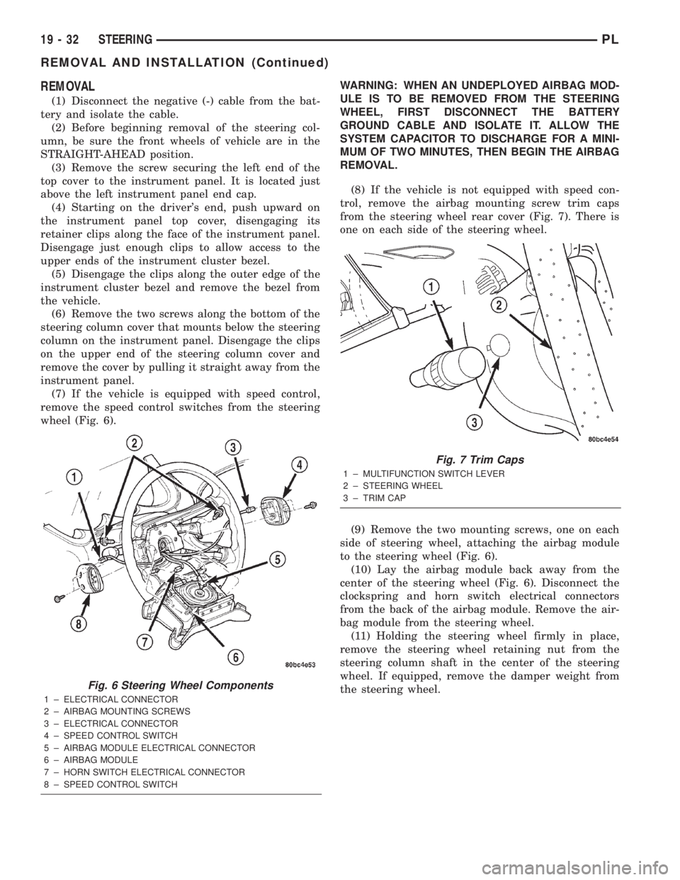
(7) If the vehicle is equipped with speed control,
remove the speed control switches from the steering
wheel (Fig. 6).WARNING: WHEN AN UNDEPLOYED AIRBAG MOD-
ULE IS TO BE REMOVED FROM THE STEERING
WHEEL, FIRST DISCONNECT THE BATTERY
GROUND CABLE AND ISOLATE IT. ALLOW THE
SYSTEM CAPACITOR TO DISCHARGE FOR A MINI-
MUM OF TWO MINUTES, THEN BEGIN THE AIRBAG
REMOVAL.
(8) If the vehicle is not equipped with speed con-
trol, remove the airbag mounting screw trim caps
from the steering wheel rear cover (Fig. 7). There is
one on each side of the steering wheel.
(9) Remove the two mounting screws, one on each
side of steering wheel, attaching the airbag module
to the steering wheel (Fig. 6).
(10) Lay the airbag module back away from the
center of the steering wheel (Fig. 6). Disconnect the
clockspring and horn switch electrical connectors
from the back of the airbag module. Remove the air-
bag module from the steering wheel.
(11) Holding the steering wheel firmly in place,
remove the steering wheel retaining nut from the
steering column shaft in the center of the steering
wheel. If equipped, remove the damper weight from
the steering wheel.
Fig. 6 Steering Wheel Components
1 ± ELECTRICAL CONNECTOR
2 ± AIRBAG MOUNTING SCREWS
3 ± ELECTRICAL CONNECTOR
4 ± SPEED CONTROL SWITCH
5 ± AIRBAG MODULE ELECTRICAL CONNECTOR
6 ± AIRBAG MODULE
7 ± HORN SWITCH ELECTRICAL CONNECTOR
8 ± SPEED CONTROL SWITCH
Fig. 7 Trim Caps
1 ± MULTIFUNCTION SWITCH LEVER
2 ± STEERING WHEEL
3 ± TRIM CAP
19 - 32 STEERINGPL
REMOVAL AND INSTALLATION (Continued)
Page 908 of 1285
bolt nut to a torque of 28 N´m (250 in. lbs.). Install
the pinch bolt retainer pin.
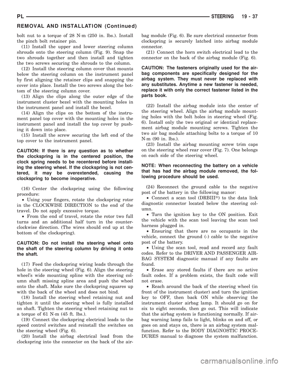
(11) Install the upper and lower steering column
shrouds onto the steering column (Fig. 9). Snap the
two shrouds together and then install and tighten
the two screws securing the shrouds to the column.
(12) Install the steering column cover that mounts
below the steering column on the instrument panel
by first aligning the retainer clips and snapping the
cover into place. Install the two screws along the bot-
tom of the steering column cover.
(13) Align the clips along the outer edge of the
instrument cluster bezel with the mounting holes in
the instrument panel and install the bezel.
(14) Align the clips on the bottom of the instru-
ment panel top cover with the mounting holes in the
instrument panel and install the top cover by push-
ing it down into place.
(15) Install the screw securing the left end of the
top cover to the instrument panel.
CAUTION: If there is any question as to whether
the clockspring is in the centered position, the
clock spring needs to be recentered before install-
ing the steering wheel. If the clockspring is not cen-
tered, it may be overextended, causing the
clockspring to become inoperative.
(16) Center the clockspring using the following
procedure:
²Using your fingers, rotate the clockspring rotor
in the CLOCKWISE DIRECTION to the end of the
travel. Do not apply excessive torque.
²From the end of travel, rotate the rotor two full
turns and an additional half turn in the counter-
clockwise direction. (The wires should end up at the
bottom of the clockspring).
CAUTION: Do not install the steering wheel onto
the shaft of the steering column by driving it onto
the shaft.
(17) Feed the clockspring wiring leads through the
hole in the steering wheel (Fig. 6). Align the steering
wheel's wide mounting spline with the steering col-
umn shaft missing spline area and push the wheel
onto the shaft. Make sure the clockspring squares up
with the back of the wheel and does not bind.
(18) Install the steering wheel retaining nut and
tighten it until the steering wheel is fully installed
on shaft. Tighten the steering wheel retaining nut to
a torque of 61 N´m (45 ft. lbs.).
(19) Connect the clockspring electrical leads to the
speed control switches and reinstall the switches on
the steering wheel (Fig. 6).
(20) Install the airbag electrical lead from the
clockspring into the connector on the back of the air-bag module (Fig. 6). Be sure electrical connector from
clockspring is securely latched into airbag module
connector.
(21) Connect the horn switch electrical lead to the
connector on the back of the airbag module (Fig. 6).
CAUTION: The fasteners originally used for the air-
bag components are specifically designed for the
airbag system. They must never be replaced with
any substitutes. Anytime a new fastener is needed,
replace it with only the correct fastener listed in the
parts book.
(22) Install the airbag module into the center of
the steering wheel. Align the airbag module mount-
ing holes with the bolt holes in steering wheel (Fig.
6). Install only the two original or identical replace-
ment airbag module mounting screws. Tighten the
two air bag module attaching bolts to a torque of 10
N´m (90 in. lbs.).
(23) Install the airbag mounting screw trim caps
on the steering wheel rear cover (Fig. 7). One belongs
on each side of the steering wheel.
NOTE: When reconnecting the battery on a vehicle
that has had the airbag module removed, the fol-
lowing procedure should be used.
(24) Reconnect the ground cable to the negative
post of the battery in the following manor:
²Connect a scan tool (DRBIIIt) to the data link
diagnostic connector located below the steering col-
umn.
²Turn the ignition key to the ON position. Exit
the vehicle with the scan tool leaving the scan tool
harness plugged in.
²Ensuring that there are no occupants in the
vehicle, connect the ground (-) cable to the negative
post of the battery.
²Using the scan tool, read and record any fault
codes. Refer to the DRIVER AND PASSENGER AIR-
BAG SYSTEM diagnostic manual if any faults are
found.
²Erase any stored faults if there are no active
fault codes. If a problem exists, the fault code will
not erase.
²Reach around the back of the steering wheel (in
front of the instrument cluster) and turn the ignition
key to OFF, then back ON while observing the
instrument cluster airbag lamp. It should go on for
six to eight seconds, then go out. This will indicate
that the airbag system is functioning normally. If air-
bag warning lamp fails to light, blinks on and off, or
goes on and stays on, there is an airbag system mal-
function. Refer to the BODY DIAGNOSTIC PROCE-
DURES manual to diagnose the system malfunction.
PLSTEERING 19 - 37
REMOVAL AND INSTALLATION (Continued)
Page 1092 of 1285
MISFIRE
²Same Misfire Warm-Up StateÐ Indicates if
the misfire occurred when the engine was warmed up
(above 160É F).
²In Similar Misfire WindowÐ An indicator
that 'Absolute MAP When Misfire Occurred' and
'RPM When Misfire Occurred' are all in the same
range when the failure occurred. Indicated by switch-
ing from 'NO' to 'YES'.
²Absolute MAP When Misfire OccurredÐ
The stored MAP reading at the time of failure.
Informs the user at what engine load the failure
occurred.
²Absolute MAPÐ A live reading of engine load
to aid the user in accessing the Similar Conditions
Window.
²RPM When Misfire OccurredÐ The stored
RPM reading at the time of failure. Informs the user
at what engine RPM the failure occurred.
²Engine RPMÐ A live reading of engine RPM
to aid the user in accessing the Similar Conditions
Window.
²Adaptive Memory FactorÐ The PCM uti-
lizes both Short Term Compensation and Long Term
Adaptive to calculate the Adaptive Memory Factor
for total fuel correction.
²200 Rev CounterÐ Counts 0±100 720 degree
cycles.
²SCW Cat 200 Rev CounterÐ Counts when in
similar conditions.
²SCW FTP 1000 Rev CounterÐ Counts 0±4
when in similar conditions.
²Misfire Good Trip CounterÐ Counts up to
three to turn OFF the MIL.
MALFUNCTION INDICATOR LAMP (MIL)
OPERATION
As a functional test, the Malfunction Indicator
Lamp (MIL) illuminates at key-on before engine
cranking. Whenever the Powertrain Control Module
(PCM) sets a Diagnostic Trouble Code (DTC) that
affects vehicle emissions, it illuminates the MIL. If a
problem is detected, the PCM sends a message over
the PCI Bus to the instrument cluster to illuminate
the lamp. The PCM illuminates the MIL only for
DTC's that affect vehicle emissions. The MIL stays
on continuously when the PCM has entered a
Limp-In mode or identified a failed emission compo-
nent or system. The MIL remains on until the DTC
is erased. Refer to the Diagnostic Trouble Code
charts in this group for emission related codes.
Also, the MIL either flashes or illuminates contin-
uously when the PCM detects active engine misfire.
Refer to Misfire Monitoring in this section.Additionally, the PCM may reset (turn off) the MIL
when one of the following occur:
²PCM does not detect the malfunction for 3 con-
secutive trips (except misfire and fuel system moni-
tors).
²PCM does not detect a malfunction while per-
forming three successive engine misfire or fuel sys-
tem tests. The PCM performs these tests while the
engine is operating within6375 RPM of and within
10 % of the load of the operating condition at which
the malfunction was first detected.
DRB III STATE DISPLAY TEST MODE
OPERATION
The switch inputs to the Powertrain Control Mod-
ule (PCM) have two recognized states; HIGH and
LOW. For this reason, the PCM cannot recognize the
difference between a selected switch position versus
an open circuit, a short circuit, or a defective switch.
If the State Display screen shows the change from
HIGH to LOW or LOW to HIGH, assume the entire
switch circuit to the PCM functions properly. From
the state display screen, access either State Display
Inputs and Outputs or State Display Sensors.
DRB III CIRCUIT ACTUATION TEST MODE
OPERATION
The Circuit Actuation Test Mode checks for proper
operation of output circuits or devices the Powertrain
Control Module (PCM) may not internally recognize.
The PCM attempts to activate these outputs and
allow an observer to verify proper operation. Most of
the tests provide an audible or visual indication of
device operation (click of relay contacts, fuel spray,
etc.). Except for intermittent conditions, if a device
functions properly during testing, assume the device,
its associated wiring, and driver circuit work cor-
rectly.
DIAGNOSTIC TROUBLE CODES
DESCRIPTION
A Diagnostic Trouble Code (DTC) indicates the
PCM has recognized an abnormal condition in the
system.
Remember that DTC's are the results of a sys-
tem or circuit failure, but do not directly iden-
tify the failed component or components.
NOTE: For a list of DTC's, refer to the charts in this
section.
PLEMISSION CONTROL SYSTEMS 25 - 5
DESCRIPTION AND OPERATION (Continued)