2000 DODGE NEON relay
[x] Cancel search: relayPage 643 of 1285

P36 18PK/VT DOOR UNLOCK DRIVER
P33 18OR/BK DOOR LOCK DRIVER
4 2 GRAY
OXYGEN SENSOR 1/1 SIGNAL 20BK/DG K41 4OXYGEN SENSOR GROUND K127 18BK/OR 3
HEATED OXYGEN SENSOR RELAY CONTROL K79 18OR/RD 2
AUTOMATIC SHUT DOWN RELAY OUTPUT 18DG/OR A142 1
FUNCTION CIRCUIT CAV
CAV CIRCUIT FUNCTION
1
A142 18DG/ORAUTOMATIC SHUT DOWN RELAY OUTPUT
2Z1 18BKGROUND
3K127 18BK/OROXYGEN SENSOR GROUND
4K141 20TN/WT
OXYGEN SENSOR 1/2 SIGNAL
2
41
3
1/2 DOWNSTREAMOXYGEN SENSOR
(2.0L)
FUSED IGNITION SWITCH OUTPUT (RUN) 18WT F20 3PARK/NEUTRAL POSITION SWITCH SENSE 18BR/YL T41 2BACK-UP LAMP FEED 18VT/BK L1 1FUNCTION CIRCUIT CAV
POSITION SWITCHPARK/NEUTRAL
BLACK
3 1
PASSENGER
DOOR LOCK
MOTOR OXYGEN SENSOR
1/1 UPSTREAM
BLACK
34
2 1
4
3
2
-
- 1
FUNCTION CIRCUIT CAV
--
LOCK SWITCH PASSENGER CYLINDER
GROUND Z14 18BK 2PASSENGER DOOR SWITCH MUX P96 18LG 1
FUNCTION CIRCUIT CAV
GRAY 3 1
AIRBAG PASSENGER
YELLOW
1 4
PASSENGER AIRBAG LINE 2 18BK/YL R42 4PASSENGER AIRBAG LINE 1 18DG/YL R44 3
- - 2
- - 1
FUNCTION CIRCUIT CAV
BLACK
(ATX)
8W - 80 - 34 8W-80 CONNECTOR PIN-OUTSPL
008W-10PLI08034
Page 646 of 1285

HEATED OXYGEN SENSOR RELAY CONTROL FUEL INJECTOR NO. 2 DRIVER FUEL INJECTOR NO. 4 DRIVER
37MAP SENSOR SIGNAL 20DG/RD K1 36MODULE - C1CONTROL POWERTRAIN
25
26 K2 20TN/BK
27
28 - -
29 - -
30 K41 20BK/DG OXYGEN SENSOR 1/1 SIGNAL
31
32 K24 20GY/BK CRANKSHAFT POSITION SENSOR SIGNAL
33 K44 20TN/YL CAMSHAFT POSITION SENSOR SIGNAL
34
35 K22 20OR/DB THROTTLE POSITION SENSOR SIGNAL
38 C20 18BR/OR A/C SWITCH SENSE
39 - -
40
BLACK
10 120 1130 2140 31
KNOCK SENSOR SIGNAL 20DB/LG K42 24CLUTCH SWITCH K119 18LG/BK 23- - 22- - 21FUSED IGNITION SWITCH OUTPUT (ST-RUN) 18DB/WT F12
20- - 19K79 18OR/RD 1818TN K12 1718LB/BR K14 16- - 15- - 14FUEL INJECTOR NO. 1 DRIVER 18WT/DB K11 13 12 11GROUND 18BK/TN Z12 10- - 9GENERATOR FIELD DRIVER (+) K20 18DG 8FUEL INJECTOR NO. 3 DRIVER 18YL/WT K13 7AUTOMATIC SHUT DOWN RELAY OUTPUT 18DG/OR A142 6SPEED CONTROL POWER SUPPLY 20YL/RD V32 5 4IGNITION COIL NO. 2 DRIVER 18DB/TN K17 3 2- - 1FUNCTION CIRCUIT CAV
ENGINE COOLANT TEMPERATURE SENSOR SIGNAL --
--
K19 18BK/GY IGNITION COIL NO. 1 DRIVER
ENGINE OIL PRESSURE SWITCH SENSE G6 20GY
K127 18BK/OR
OXYGEN SENSOR GROUND
20TN K90 ENGINE STARTER MOTOR RELAY CONTROL
--
--
SPEED CONTROL- - --
PL8W-80 CONNECTOR PIN-OUTS 8W - 80 - 37
PLI08037008W-10
Page 647 of 1285

POWERTRAIN
CONTROL
MODULE - C2
61 K6 18VT/WT 5V SUPPLY
62 K29 20WT/PK BRAKE LAMP SWITCH SENSE
63 - -
64 C28 18DB/OR A/C COMPRESSOR CLUTCH RELAY CONTROL
65 D21 20PK SCI TRANSMIT
66 G7 20WT/OR VEHICLE SPEED SENSOR SIGNAL
67 K51 18DB/YL AUTOMATIC SHUT DOWN RELAY CONTROL
68 K52 20PK/BK PROPORTIONAL EVAP/PURGE SOLENOID CONTROL
69 - -
70
71
72 K107 18YL LEAK DETECTION PUMP SWITCH SENSE
73
74 K31 18BR FUEL PUMP RELAY CONTROL
75 D20 20LG SCI RECIEVE
76 CLUTCH INTERLOCK SWITCH SENSE
77 K106 18WT/DG LEAK DETECTION PUMP SOLENOID CONTROL
78
79K54 18OR/BK TORQUE CONVERTOR CLUTCH SOLENOID CONTROL
80 V35 20LG/RD SPEED CONTROL VENT SOLENOID CONTROL
BLACK
71 8061 7051 6041 50
- - 60 59
20VT K59 58
IDLE AIR CONTROL NO. 1 DRIVER 20GY/RD K39 57
SPEED CONTROL VACUUM SOLENOID CONTROL 20TN/RD V36 56
55
- - 54
- - 53
INLET AIR TEMPERATURE SENSOR SIGNAL 20VT/LG G31 52
OXYGEN SENSOR 1/2 SIGNAL 20TN/WT K141 51
GROUND 20BK/TN Z12 50
20YL/BK K60 49
IDLE AIR CONTROL NO. 3 DRIVER 20BR/WT K40 48
GROUND 18BK/WT Z11 47
FUSED B(+) 18RD/WT A14 46
POWER STEERING PRESSURE SWITCH SENSE 20WT K10 45
8V SUPPLY 20OR K7 44
SENSOR GROUND 20BK/LB K4 43
- - 42
SPEED CONTROL SWITCH SIGNAL 20RD/LG V37 41
FUNCTION CIRCUIT CAV
IDLE AIR CONTROL NO. 2 DRIVER
IDLE AIR CONTROL NO. 4 DRIVER C27 18DB/PK RADIATOR FAN RELAY CONTROL
D25 20VT/YL
PCI BUS
K108 20DB EVAPORATIVE EMISSION SOLENOID SENSE
G9 18GY/BK RED BRAKE WARNING INDICATOR DRIVER
--
-- 76 T41 18BR/YL PARK/NEUTRAL POSITION SWITCH SENSE
20YL/RD T141
SPEED CONTROLEXCEPT BUILT-UP-EXPORT
MTX
ATX
8W - 80 - 38 8W-80 CONNECTOR PIN-OUTSPL
J008W-10PLI08038
Page 648 of 1285

CAV CIRCUIT FUNCTION
1 E2 20OR PANEL LAMPS DRIVER
2 Z3 20BK/OR GROUND
BLACK
12
CAV CIRCUIT FUNCTION
1 C25 12LG RADIATOR FAN RELAY OUTPUT
2 Z1 14BK GROUND
CAV CIRCUIT FUNCTION
1- -
4 X53 20DG
5 X54 20VT 1
BLACK
2
BLACK
7
1
7 1
FUSED B(+) 20PK M1 7FUSED IGNITION SWITCH OUTPUT (RUN-ACC) X12 18RD/WT 6
PANEL LAMPS DRIVER 20OR E2 5
HEADLAMP SWITCH OUTPUT 20BK/YL L7 4
20DB/RD X56 3
20BR/RD X55 2
- - 1
FUNCTION CIRCUIT CAV
PRNDL
LAMP
RADIATOR
FAN MOTOR
RADIO - C1
RADIO - C2
GRAYLEFT REAR SPEAKER (+) 20BR/YL X51 2
X52 20DB/WT3
LEFT REAR SPEAKER (-)
20BR/LB X57 6
RIGHT REAR SPEAKER (-) 20DB/OR X58 7
RIGHT REAR SPEAKER (+)
RIGHT FRONT SPEAKER (+) LEFT FRONT SPEAKER (+)
RIGHT FRONT SPEAKER (-) LEFT FRONT SPEAKER (-) 1
BLACK
2
SOLENOID EVAP/PURGE PROPORTIONAL
PROPORTIONAL EVAP/PURGE SOLENOID CONTROL K52 20PK/BK 2EVAPORATIVE EMISSION SOLENOID SENSE K108 20DB 1
FUNCTION CIRCUIT CAV
PL8W-80 CONNECTOR PIN-OUTS 8W - 80 - 39
PLI08039008W-10
Page 649 of 1285

LHD
RHD
Z2 22BK/LGGROUND
F9 20RD/BKFUSED B(+)
PASSENGER DOOR SWITCH MUX
P96 20LG/BK
- -
L7 20BK/YLDIMMER SWITCH LOW BEAM OUTPUT
REMOTE KEYLESS
ENTRY MODULE
1411
12
13
9 5
6
8 7 3
4 2 1CIRCUIT CAV
10
21 15
18
19 17 16
20
24 23 22
25
26
F35 18RDHEADLAMP SWITCH OUTPUT
P33 18OR/BKFUSED B(+)
P34 18PK/BKDOOR LOCK DRIVER
P36 18PK/VTDOOR UNLOCK DRIVER
M9 20DB/ORDOOR UNLOCK DRIVER
PASSENGER DOOR AJAR/ RKE SENSE
P97 20LGDRIVER DOOR SWITCH MUX
Z1 20BKGROUND
X161 20WTRKE ANTENNA
X5 22WT/RDDISPLAY BACKLIGHT
Q2 16LG/BKDECKLID RELEASE RELAY OUTPUT
G69 20BK/ORVTSS INDICATOR DRIVER
X3 22BK/RDHORN RELAY CONTROL
D25 20VT/YLPCI BUS
G120 18WT/BKINTRUSION SENSOR SIGNAL
M1 20PKFUSED B(+)
G5 20DB/WTFUSED IGNITION SWITCH OUTPUT (ST-RUN)
G70 20BR/TNHOOD AJAR SWITCH SENSE
G71 20VT/YLDECKLID SECURITY SWITCH SENSE
G75 18TNDRIVER DOOR AJAR SWITCH SENSE
X161 20WTJAPAN ANTENNA L4 16VT/WT
BUILT-UP-EXPORT
1
13
14
26REAR WINDOW DEFOGGER RELAY OUTPUT
C15 12BKPANEL LAMPS DRIVER
E2 20OR Z2 22BK/LGGROUND F20 20WTFUSED IGNITION SWITCH OUTPUT (RUN) A4 12BK/RDFUSED B(+)
SWITCH
51
DEFOGGER REAR WINDOW
FUNCTION
CAV CIRCUIT
1
2
4 3
5
F35 18RD/YL
FUSED B(+) 3
5
C15 12BK/WTRAER WINDOW DEFOGGER RELAY OUTPUT
INTRUSION SENSOR SIGNAL
G120 18WT/DB20
BLACK
BLACK
FUNCTION
8W - 80 - 40 8W-80 CONNECTOR PIN-OUTSPL
J008W-10PLI08040
Page 753 of 1285

CAUTION: When using the ASD Fuel System Test,
the Auto Shutdown (ASD) relay will remain ener-
gized for 7 minutes or until the ignition switch is
turned to the OFF position, or Stop All Test is
selected.
EXHAUST MANIFOLD
REMOVAL
(1) Disconnect negative cable from battery.
(2) Raise vehicle on hoist.
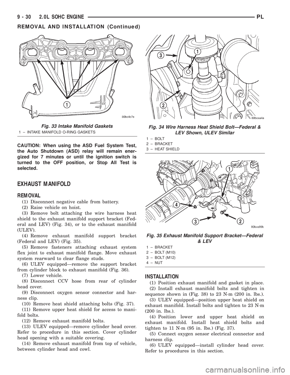
(3) Remove bolt attaching the wire harness heat
shield to the exhaust manifold support bracket (Fed-
eral and LEV) (Fig. 34), or to the exhaust manifold
(ULEV).
(4) Remove exhaust manifold support bracket
(Federal and LEV) (Fig. 35).
(5) Remove fasteners attaching exhaust system
flex joint to exhaust manifold flange. Move exhaust
system rearward to clear flange studs.
(6) ULEV equippedÐremove the support bracket
from cylinder block to exhaust manifold (Fig. 36).
(7) Lower vehicle.
(8) Disconnect CCV hose from rear of cylinder
head cover.
(9) Disconnect oxygen sensor connector and har-
ness clip.
(10) Remove heat shield attaching bolts (Fig. 37).
(11) Remove upper heat shield for access to mani-
fold bolts.
(12) Remove exhaust manifold bolts.
(13) ULEV equippedÐremove cylinder head cover.
Refer to procedure in this section. Cover cylinder
head opening with a suitable covering.
(14) Remove exhaust manifold from top of vehicle,
between cylinder head and cowl.
INSTALLATION
(1) Position exhaust manifold and gasket in place.
(2) Install exhaust manifold bolts and tighten in
sequence shown in (Fig. 38) to 23 N´m (200 in. lbs.).
(3) ULEV equippedÐposition upper heat shield on
exhaust manifold. Install bolts and tighten to 23 N´m
(200 in. lbs.).
(4) Position lower and upper heat shield on
exhaust manifold. Install heat shield bolts and
tighten to 11 N´m (95 in. lbs.) (Fig. 37).
(5) Connect oxygen sensor electrical connector and
harness clip.
(6) ULEV equippedÐinstall cylinder head cover.
Refer to procedures in this section.
Fig. 33 Intake Manifold Gaskets
1 ± INTAKE MANIFOLD O-RING GASKETS
Fig. 34 Wire Harness Heat Shield BoltÐFederal &
LEV Shown, ULEV Similar
1 ± BOLT
2 ± BRACKET
3 ± HEAT SHIELD
Fig. 35 Exhaust Manifold Support BracketÐFederal
& LEV
1 ± BRACKET
2 ± BOLT (M10)
3 ± BOLT (M12)
4 ± NUT
9 - 30 2.0L SOHC ENGINEPL
REMOVAL AND INSTALLATION (Continued)
Page 822 of 1285

FUEL SYSTEM
TABLE OF CONTENTS
page page
FUEL DELIVERY SYSTEM.................... 1FUEL INJECTION SYSTEM.................. 21
FUEL DELIVERY SYSTEM
TABLE OF CONTENTS
page page
DESCRIPTION AND OPERATION
FUEL REQUIREMENTS.....................1
GASOLINE/OXYGENATE BLENDS.............2
FUEL DELIVERY SYSTEM...................3
FUEL PUMP MODULE......................3
ELECTRIC FUEL PUMP.....................4
FUEL GAUGE SENDING UNIT................4
FUEL FILTER/FUEL PRESSURE REGULATOR....4
FUEL TANK..............................4
FUEL RAIL...............................4
FUEL INJECTORS.........................5
PRESSURE-VACUUM FILLER CAP............5
ONBOARD REFUELING VAPOR RECOVERY....6
CONTROL VALVE/PRESSURE RELIEF.........6
QUICK-CONNECT FITTINGS.................6
ROLLOVER VALVES.......................7
FUEL TUBES/LINES/HOSES AND CLAMPS......8
SERVICE PROCEDURES
FUEL SYSTEM PRESSURE RELEASE
PROCEDURE...........................8INJECTOR CONNECTOR....................8
DRAINING FUEL TANK.....................9
HOSES AND CLAMPS......................9
QUICK-CONNECT FITTINGS.................9
REMOVAL AND INSTALLATION
AUTOMATIC SHUTDOWN RELAY............12
FUEL PUMP RELAY.......................12
FUEL PUMP MODULE.....................12
FUEL FILTER / PRESSURE REGULATOR......13
FUEL PUMP INLET STRAINER..............14
FUEL LEVEL SENSOR.....................14
FUEL INJECTORS........................15
FUEL TANK.............................16
FUEL FILLER NECK.......................17
ACCELERATOR PEDAL....................18
THROTTLE CABLE.......................19
SPECIFICATIONS
TORQUE...............................20
DESCRIPTION AND OPERATION
FUEL REQUIREMENTS
OPERATION
Your engine is designed to meet all emissions reg-
ulations and provide excellent fuel economy and per-
formance when using high quality unleaded gasoline
having an octane rating of 87. The use of premium
gasoline is not recommended. The use of premium
gasoline will provide no benefit over high quality reg-
ular gasoline, and in some circumstances may result
in poorer performance.
Light spark knock at low engine speeds is not
harmful to your engine. However, continued heavyspark knock at high speeds can cause damage and
immediate service is required. Engine damage result-
ing from operation with a heavy spark knock may
not be covered by the new vehicle warranty.
Poor quality gasoline can cause problems such as
hard starting, stalling and hesitations. If you experi-
ence these symptoms, try another brand of gasoline
before considering service for the vehicle.
The American Automobile Manufacturers Associa-
tion, AAMA, has issued gasoline specifications to
define the minimum fuel properties necessary to
deliver enhanced performance and durability for your
vehicle. DaimlerChrysler Corporation recommends
the use of gasoline that meet the AAMA specifica-
tions if they are available.
PLFUEL SYSTEM 14 - 1
Page 825 of 1285

The inlet strainer, fuel pressure regulator and fuel
level sensor are the only serviceable items. If the fuel
pump requires service, replace the fuel pump module.
ELECTRIC FUEL PUMP
DESCRIPTION
The electric fuel pump is located in and is part of
the fuel pump module. It is a positive displacement,
gerotor type, immersible pump with a permanent
magnet electric motor. The fuel pump module is sus-
pended in fuel in the fuel tank.
OPERATION
The pump draws fuel through a strainer and
pushes it through the motor to the outlet. The pump
contains a check valve. The valve, in the pump out-
let, maintains pump pressure during engine off con-
ditions. The fuel pump relay provides voltage to the
fuel pump. The fuel pump has a maximum dead-
headed pressure output of approximately 880 kPa
(130 psi). The regulator adjusts fuel system pressure
to approximately 338 kPa (49 psi).
FUEL GAUGE SENDING UNIT
DESCRIPTION
The fuel gauge sending unit (fuel level sensor) is
attached to the side of the fuel pump module. The
sending unit consists of a float, an arm, and a vari-
able resistor (track). The resistor track is used to
send electrical signals to the instrument cluster for
fuel gauge operation and are then transmitted to the
engine controller for OBDII emission requirements.
OPERATION
For fuel gauge operation:As fuel level
increases, the float and arm move up. This increases
the sending unit resistance, causing the fuel gauge to
read full. As fuel level decreases, the float and arm
move down. This decreases the sending unit resis-
tance causing the fuel gauge to read empty.
After this fuel level signal is sent to the instru-
ment cluster, the instrument cluster will transmit
the data across the J1850 bus circuit to the PCM.
For OBD II emission requirements:The voltage
signal is sent to the instrument cluster to indicate
fuel level. The cluster transmits the fuel level to the
PCM where it is used to prevent a false setting of
misfire and fuel system monitor trouble codes. This
occurs if the fuel level in the tank is less than
approximately 15 percent of its rated capacity.
FUEL FILTER/FUEL PRESSURE REGULATOR
DESCRIPTION
A combination fuel filter and fuel pressure regula-
tor is used on all gas powered engines. It is located
on the top of the fuel pump module. A separate frame
mounted fuel filter is not used.
OPERATION
Fuel Pressure Regulator Operation:The pres-
sure regulator is a mechanical device that is cali-
brated to maintain fuel system operating pressure of
approximately 338 kPa (49 psi) at the fuel injectors.
It contains a diaphragm, calibrated springs and a
fuel return valve. The internal fuel filter (Fig. 2) is
also part of the assembly.
Fuel is supplied to the filter/regulator by the elec-
tric fuel pump through an opening tube at the bot-
tom of filter/regulator.
The fuel pump module contains a check valve to
maintain some fuel pressure when the engine is not
operating. This will help to start the engine.
If fuel pressure at the pressure regulator exceeds
approximately 49 psi, an internal diaphragm closes
and excess fuel pressure is routed back into the tank
through the pressure regulator. A separate fuel
return line is not used with any gas powered engine.
FUEL TANK
OPERATION
All models pass a full 360 degree rollover test
without fuel leakage. To accomplish this, fuel and
vapor flow controls are required for all fuel tank con-
nections.
All models are equipped with either one or two
rollover valves mounted into the top of the fuel tank
(or pump module).
An evaporation control system is connected to the
rollover valve(s) to reduce emissions of fuel vapors
into the atmosphere. When fuel evaporates from the
fuel tank, vapors pass through vent hoses or tubes to
a charcoal canister where they are temporarily held.
When the engine is running, the vapors are drawn
into the intake manifold. Certain models are also
equipped with a self-diagnosing system using a Leak
Detection Pump (LDP). Refer to the Emission Control
System for additional information.
FUEL RAIL
DESCRIPTION
The fuel rail supplies the necessary fuel to each
individual fuel injector and is mounted to the intake
manifold (Fig. 3).
14 - 4 FUEL SYSTEMPL
DESCRIPTION AND OPERATION (Continued)