2000 DODGE NEON spark
[x] Cancel search: sparkPage 5 of 1285

30,000 Miles (48 000 km) or at 24 months
²Change the engine oil.
²Replace the engine oil filter.
²Lubricate the front suspension lower ball joint.
²Inspect the tie rod ends and boot seals.
²Adjust the drive belt tension.
²Replace the engine air cleaner element (fil-
ter).
²Replace the engine spark plugs
²Change the automatic transaxle fluid.
37,500 Miles (60 000 km) or at 30 months
²Change the engine oil.
²Replace the engine oil filter.
45,000 Miles (72 000 km) or at 36 months
²Change the engine oil.
²Replace the engine oil filter.
²Inspect the front brake pads and rear brake lin-
ings.
²Adjust the drive belt tension.
²Flush and replace the engine coolant at 36
months, regardless of mileage.
52,500 Miles (84 000 km) or at 42 months
²Change the engine oil.
²Replace the engine oil filter.
²Flush and replace the engine coolant if not done
at 36 months.
60,000 Miles (96 000 km) or at 48 months
²Change the engine oil.
²Replace the engine oil filter.
²Check the PCV valve and replace, if neces-
sary. Not required if previously changed.*
²Lubricate the front suspension lower ball joints.
²Replace the drive belts.
²Replace the engine air cleaner element (fil-
ter).
²Replace the ignition cables.
²Replace the spark plugs.
²Change the automatic transaxle fluid.
67,500 Miles (108 000 km) or at 54 months
²Change the engine oil.
²Replace the engine oil filter.
²Inspect the front brake pads and rear brake lin-
ings.
75,000 Miles (120 000 km) or at 60 months
²Change the engine oil.
²Replace the engine oil filter.
²Adjust the drive belt tension.
²Flush and replace engine coolant if has been
30,000 miles (48 000 km) or 24 months since last
change.
82,500 Miles (132 000 km) or at 66 months
²Change the engine oil.
²Replace the engine oil filter.
²Flush and replace engine coolant if it has been
30,000 miles (48 000 km) or 24 months since last
change.
90,000 Miles (144 000 km) or at 72 months
²Change the engine oil.
²Replace the engine oil filter.
²Check the PCV valve and replace, if neces-
sary. Not required if previously changed.*
²Lubricate the front suspension lower ball joints.
²Inspect the front brake pads and rear brake lin-
ings.
²Adjust the drive belt tension.
²Replace the engine air cleaner element (fil-
ter).
²Replace the spark plugs.
²Inspect the serpentine drive belt, replace if nec-
essary. This maintenance is not required if the belt
was previously replaced.
²Change the automatic transaxle fluid.
97,500 Miles (156 000 km) or at 78 months
²Change the engine oil.
²Replace the engine oil filter.
105,000 Miles (168 000 km) or at 84 months
²Change the engine oil.
²Replace the engine oil filter.
²Replace the engine timing belt.
²Adjust the drive belt tension.
*This maintenance is recommended by Daimler-
Chrysler Corporation to the owner but is not
required to maintain the emissions warranty.
NOTE: Inspection and service should also be per-
formed anytime a malfunction is observed or sus-
pected. Retain all receipts.
SCHEDULE ± B
3,000 Miles (5 000 km)
²Change the engine oil.
6,000 Miles (10 000 km)
²Change the engine oil.
²Replace the engine oil filter.
9,000 Miles (14 000 km)
²Change the engine oil.
²Inspect the front brake pads and rear brake lin-
ings.
0 - 4 LUBRICATION AND MAINTENANCEPL
SPECIFICATIONS (Continued)
Page 6 of 1285

12,000 Miles (19 000 km)
²Change the engine oil.
²Replace the engine oil filter.
15,000 Miles (24 000 km)
²Change the engine oil.
²Adjust the drive belt tension.
²Inspect theengine air cleaner element (fil-
ter).Replace as necessary.*
²Change the automatic transaxle fluid/filter and
adjust the bands.
18,000 Miles (29 000 km)
²Change the engine oil.
²Replace the engine oil filter.
²Inspect the front brake pads and rear brake lin-
ings.
21,000 Miles (34 000 km)
²Change the engine oil.
24,000 Miles (38 000 km)
²Change the engine oil.
²Replace the engine oil filter.
27,000 Miles (43 000 km)
²Change the engine oil.
²Inspect the front brake pads and rear brake lin-
ings.
30,000 Miles (48 000 km)
²Change the engine oil.
²Replace the engine oil filter.
²Inspect thePCV valveand replace as neces-
sary.*
²Lubricate the front suspension lower ball joints.
²Adjust the drive belt tension.
²Replace theengine air cleaner element (fil-
ter).
²Replace thespark plugs
²Change the automatic transaxle fluid/filter and
adjust bands.
33,000 Miles (53 000 km)
²Change the engine oil.
36,000 Miles (58 000 km)
²Change the engine oil.
²Replace the engine oil filter.
²Inspect the front brake pads and rear brake lin-
ings.
²Flush and replace the engine coolant.
39,000 Miles (62 000 km)
²Change the engine oil.
42,000 Miles (67 000 km)
²Change the engine oil.
²Replace the engine oil filter.
45,000 Miles (72 000 km)
²Change the engine oil.
²Inspect the front brake pads and rear brake lin-
ings.
²Inspect theengine air cleaner element (fil-
ter).Replace as necessary.*
²Adjust the drive belt tension.
²Change the automatic transaxle fluid/filter and
adjust bands.
48,000 Miles (77 000 km)
²Change the engine oil.
²Replace the engine oil filter.
51,000 Miles (82 000 km)
²Change the engine oil.
²Flush and replace the engine coolant.
54,000 Miles (86 000 km)
²Change the engine oil.
²Replace the engine oil filter.
²Inspect the front brake pads and rear brake lin-
ings.
57,000 Miles (91 000 km)
²Change the engine oil.
60,000 Miles (96 000 km)
²Change the engine oil.
²Replace the engine oil filter.
²Inspect thePCV valveand replace if neces-
sary.*
²Lubricate the front suspension lower ball joints.
²Replace the drive belts.
²Replace theengine air cleaner element (fil-
ter).
²Replace theignition cables
²Replace thespark plugs
²Check and replace, if necessary, theengine tim-
ing belton 3.0 liter engines.
²Change the automatic transaxle fluid/filter and
adjust bands.
63,000 Miles (101 000 km)
²Change the engine oil.
²Inspect the front brake pads and rear brake lin-
ings.
66,000 Miles (106 000 km)
²Change the engine oil.
²Replace the engine oil filter.
PLLUBRICATION AND MAINTENANCE 0 - 5
SPECIFICATIONS (Continued)
Page 7 of 1285

69,000 Miles (110 000 km)
²Change the engine oil.
72,000 Miles (115 000 km)
²Change the engine oil.
²Replace the engine oil filter.
²Inspect the front brake pads and rear brake lin-
ings.
75,000 Miles (120 000 km)
²Change the engine oil.
²Adjust the drive belt tension.
²Inspect theengine air cleaner element (fil-
ter)and replace as necessary.*
²Change the automatic transaxle fluid/filter and
adjust bands.
78,000 Miles (125 000 km)
²Change the engine oil.
²Replace the engine oil filter.
81,000 Miles (130 000 km)
²Change the engine oil.
²Flush and replace the engine coolant.
²Inspect the front brake pads and rear brake lin-
ings.
84,000 Miles (134 000 km)
²Change the engine oil.
²Replace the engine oil filter.
87,000 Miles (139 000 km)
²Change the engine oil.
90,000 Miles (144 000 km)
²Change the engine oil.
²Replace the engine oil filter.
²Inspect front brake pads and rear brake linings
²Check thePCV valveand replace if necessary.
Not required if previously changed.*
²Lubricate the front suspension lower ball joint.
²Replace theengine air cleaner element (fil-
ter).²Replace thespark plugs
²Change the automatic transaxle fluid/filter and
adjust the bands.
93,000 Miles (149 000 km)
²Change the engine oil.
96,000 Miles (154 000 km)
²Change the engine oil.
²Replace the engine oil filter.
99,000 Miles (158 000 km)
²Change the engine oil.
²Inspect the front brake pads and rear brake lin-
ings.
102,000 Miles (163 000 km)
²Change the engine oil.
²Replace the engine oil filter.
105,000 Miles (168 000 km)
²Replace theengine timing belt.
²Change the engine oil.
²Adjust the drive belt tension.
²Inspect theengine air cleaner element (fil-
ter)and replace as necessary.*
²Change the automatic transaxle fluid/filter and
adjust the bands.
²Flush and replace the engine coolant.
* This maintenance is recommended by Daimler-
Chrysler Corporation to the owner but is not
required to maintain the emissions warranty.
NOTE: Operating the vehicle more than 50% in
heavy traffic during hot weather, above 90É F (32É
C), using vehicle for police, taxi, limousine type
operation or trailer towing require the more fre-
quent transaxle service noted in Schedule ± B. Per-
form these services if vehicle usually operate under
these conditions.
Inspection and service should also be performed
anytime a malfunction is observed or suspected.
0 - 6 LUBRICATION AND MAINTENANCEPL
SPECIFICATIONS (Continued)
Page 217 of 1285

²It passes the 15 second load test. Refer to Bat-
tery Load Test.
²The built in test indicator dot is GREEN (Fig.
2).
NOTE: The battery cannot be refilled with water, it
must be replaced.
WARNING: DO NOT CHARGE A BATTERY THAT
HAS EXCESSIVELY LOW ELECTROLYTE LEVEL.
BATTERY MAY SPARK INTERNALLY AND
EXPLODE. EXPLOSIVE GASES FORM OVER THE
BATTERY. DO NOT SMOKE, USE FLAME, OR CRE-
ATE SPARKS NEAR BATTERY. DO NOT ASSIST
BOOST OR CHARGE A FROZEN BATTERY. BAT-
TERY CASING MAY FRACTURE. BATTERY ACID IS
POISON, AND MAY CAUSE SEVERE BURNS. BAT-
TERIES CONTAIN SULFURIC ACID. AVOID CON-
TACT WITH SKIN, EYES, OR CLOTHING. IN THE
EVENT OF CONTACT, FLUSH WITH WATER AND
CALL PHYSICIAN IMMEDIATELY. KEEP OUT OF
REACH OF CHILDREN.
CAUTION: Disconnect the battery NEGATIVE cable
first, before charging battery to avoid damage to
electrical systems. Lift the red battery boot cover
from the positive cable clamp. Do not exceed 16.0
volts while charging battery. Refer to the instruc-
tions supplied with charging equipment
Battery electrolyte may bubble inside of battery
case while being charged properly. If the electrolyte
boils violently, or is discharged from the vent holes
while charging, immediately reduce charging rate or
turn off charger. Evaluate battery condition. Battery
damage may occur if charging is excessive.
Some battery chargers are equipped with polarity
sensing devices to protect the charger or battery from
being damaged if improperly connected. If the bat-
tery state of charge is too low for the polarity sensor
to detect, the sensor must be bypassed for charger to
operate. Refer to operating instructions provided
with battery charger being used.
CAUTION: Charge battery until test indicator
appears green. Do not overcharge.
It may be necessary to jiggle the battery or vehicle
to bring the green dot in the test indicator into view.
After the battery has been charged to 12.4 volts or
greater, perform a load test to determine cranking
capacity. Refer to Battery Load Test in this Group. If
the battery passes the load test, the battery is OK to
use. If battery will not pass the load test, it must be
replaced. Properly clean and inspect battery holddowns, tray, terminals, cables, posts, and top before
completing service.
CHARGING COMPLETELY DISCHARGED
BATTERY
The following procedure should be used to recharge
a completely discharged battery. Unless procedure is
properly followed, a good battery may be needlessly
replaced. Refer to Battery Charging Rate Table for
proper charging time.
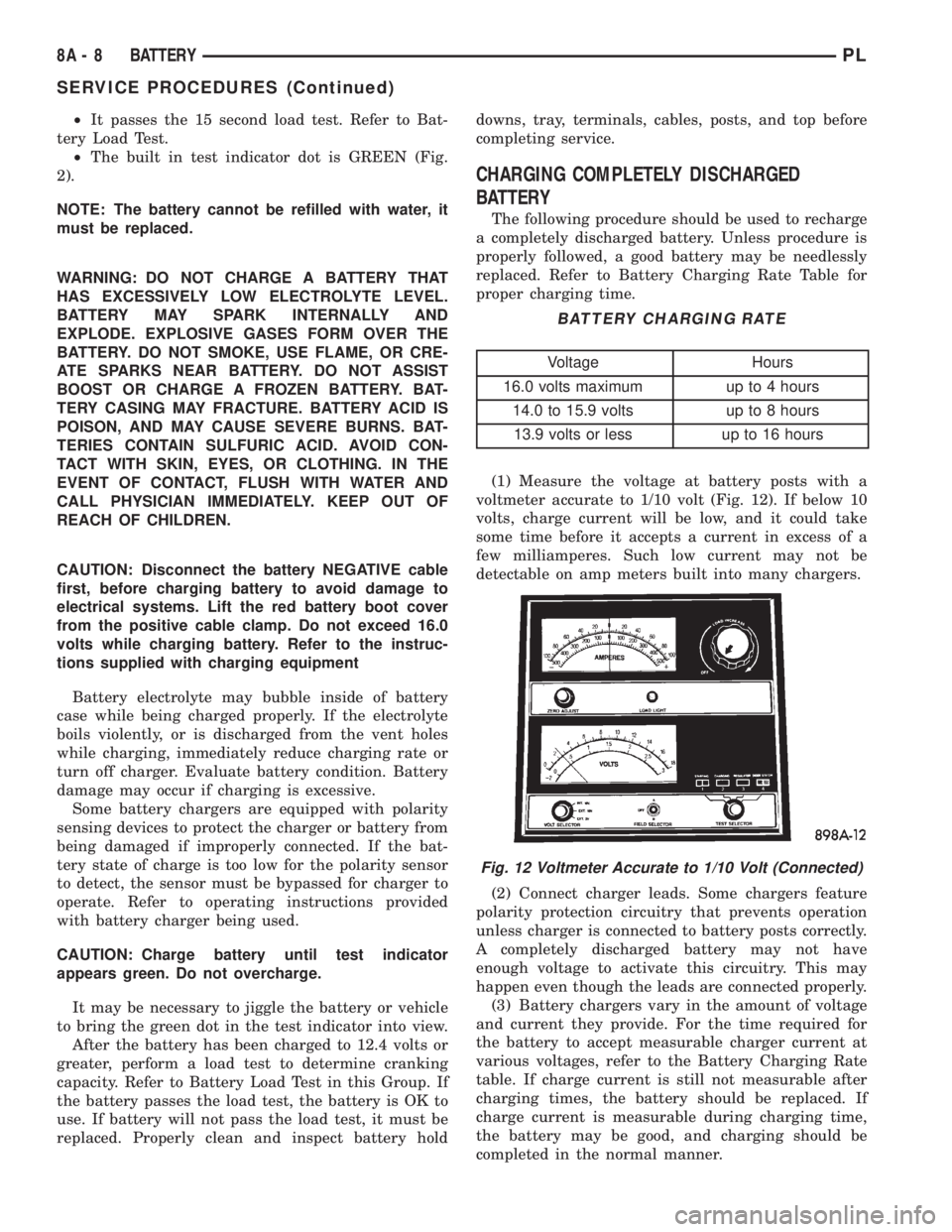
(1) Measure the voltage at battery posts with a
voltmeter accurate to 1/10 volt (Fig. 12). If below 10
volts, charge current will be low, and it could take
some time before it accepts a current in excess of a
few milliamperes. Such low current may not be
detectable on amp meters built into many chargers.
(2) Connect charger leads. Some chargers feature
polarity protection circuitry that prevents operation
unless charger is connected to battery posts correctly.
A completely discharged battery may not have
enough voltage to activate this circuitry. This may
happen even though the leads are connected properly.
(3) Battery chargers vary in the amount of voltage
and current they provide. For the time required for
the battery to accept measurable charger current at
various voltages, refer to the Battery Charging Rate
table. If charge current is still not measurable after
charging times, the battery should be replaced. If
charge current is measurable during charging time,
the battery may be good, and charging should be
completed in the normal manner.
BATTERY CHARGING RATE
Voltage Hours
16.0 volts maximum up to 4 hours
14.0 to 15.9 volts up to 8 hours
13.9 volts or less up to 16 hours
Fig. 12 Voltmeter Accurate to 1/10 Volt (Connected)
8A - 8 BATTERYPL
SERVICE PROCEDURES (Continued)
Page 222 of 1285

STARTING SYSTEMS
TABLE OF CONTENTS
page page
GENERAL INFORMATION
INTRODUCTION..........................1
SUPPLY CIRCUIT AND CONTROL CIRCUIT.....1
DESCRIPTION AND OPERATION
STARTER MOTOR.........................1
DIAGNOSIS AND TESTING
CONTROL CIRCUIT........................2
FEED CIRCUIT RESISTANCE................3
FEED CIRCUIT...........................5STARTING SYSTEM.......................6
REMOVAL AND INSTALLATION
SAFETY SWITCHES.......................8
STARTER MOTOR.........................8
STARTER RELAY.........................8
SPECIFICATIONS
STARTER MOTOR.........................9
TORQUE................................9
GENERAL INFORMATION
INTRODUCTION
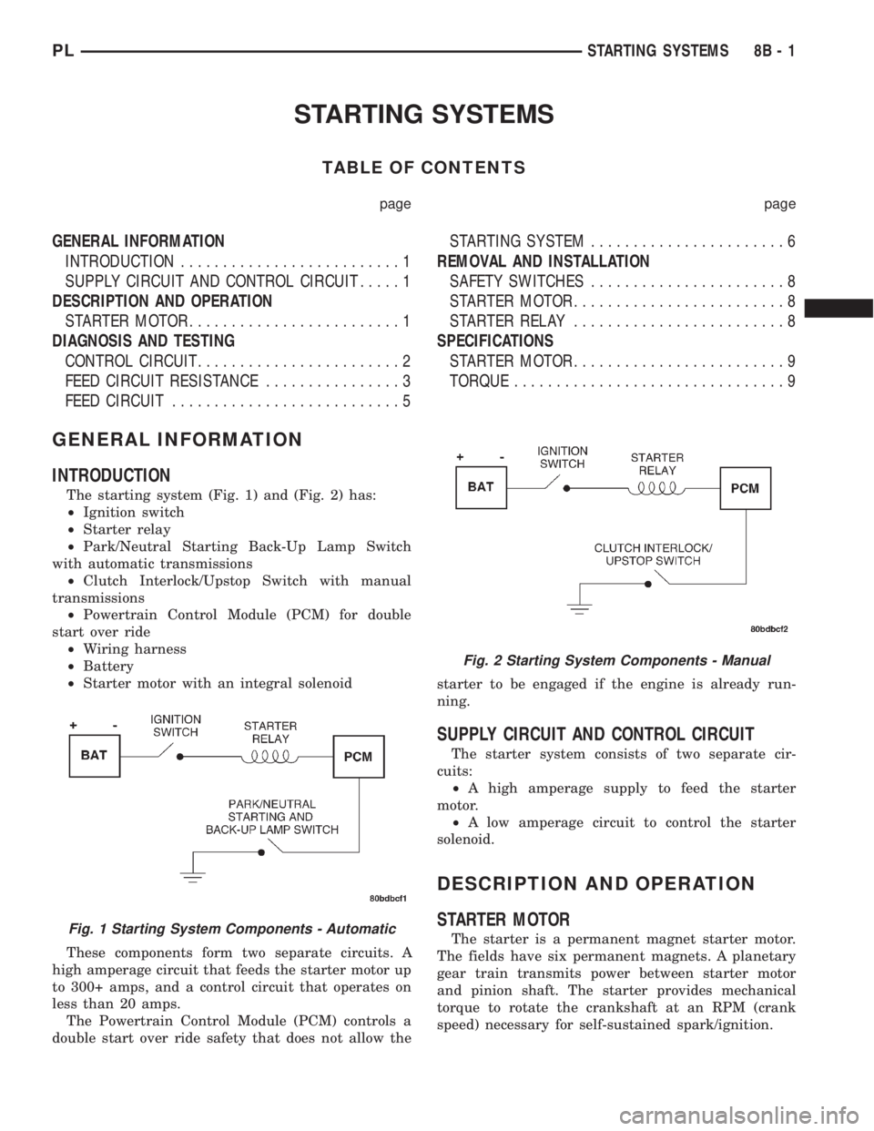
The starting system (Fig. 1) and (Fig. 2) has:
²Ignition switch
²Starter relay
²Park/Neutral Starting Back-Up Lamp Switch
with automatic transmissions
²Clutch Interlock/Upstop Switch with manual
transmissions
²Powertrain Control Module (PCM) for double
start over ride
²Wiring harness
²Battery
²Starter motor with an integral solenoid
These components form two separate circuits. A
high amperage circuit that feeds the starter motor up
to 300+ amps, and a control circuit that operates on
less than 20 amps.
The Powertrain Control Module (PCM) controls a
double start over ride safety that does not allow thestarter to be engaged if the engine is already run-
ning.
SUPPLY CIRCUIT AND CONTROL CIRCUIT
The starter system consists of two separate cir-
cuits:
²A high amperage supply to feed the starter
motor.
²A low amperage circuit to control the starter
solenoid.
DESCRIPTION AND OPERATION
STARTER MOTOR
The starter is a permanent magnet starter motor.
The fields have six permanent magnets. A planetary
gear train transmits power between starter motor
and pinion shaft. The starter provides mechanical
torque to rotate the crankshaft at an RPM (crank
speed) necessary for self-sustained spark/ignition.Fig. 1 Starting System Components - Automatic
Fig. 2 Starting System Components - Manual
PLSTARTING SYSTEMS 8B - 1
Page 236 of 1285

IGNITION SYSTEM
TABLE OF CONTENTS
page page
DESCRIPTION AND OPERATION
IGNITION SYSTEM........................1
SPARK PLUGS...........................1
SPARK PLUG CABLES.....................1
ELECTRONIC IGNITION COILS...............2
AUTOMATIC SHUTDOWN RELAY.............2
CRANKSHAFT POSITION SENSORÐPCM
INPUT................................3
CAMSHAFT POSITION SENSORÐPCM
INPUT................................4
KNOCK SENSOR..........................5
IGNITION SWITCH........................5
LOCK KEY CYLINDER......................5
IGNITION INTERLOCK.....................6
REMOVAL AND INSTALLATION
SPARK PLUG SERVICE....................6SPARK PLUG CABLE SERVICE..............6
IGNITION COIL...........................6
AUTOMATIC SHUTDOWN RELAY.............6
CAMSHAFT POSITION SENSOR..............6
CRANKSHAFT POSITION SENSOR............8
KNOCK SENSOR..........................8
IGNITION SWITCH........................8
LOCK KEY CYLINDER......................9
IGNITION INTERLOCK....................10
SPECIFICATIONS
VECI LABEL............................10
FIRING ORDERÐ2.0L....................10
TORQUE SPECIFICATION..................11
SPARK PLUG CABLE RESISTANCEÐSOHC....11
SPARK PLUG...........................11
IGNITION COIL..........................11
DESCRIPTION AND OPERATION
IGNITION SYSTEM
DESCRIPTION
The system's three main components are the coil
pack, crankshaft position sensor, and camshaft posi-
tion sensor.
OPERATION
Basic ignition timing is not adjustable.The
Powertrain Control Module (PCM) determines spark
advance. The 2.0L engines use a fixed ignition timing
system. The distributorless electronic ignition system
is referred to as the Direct Ignition System (DIS).
SPARK PLUGS
The 2.0L engines uses resistor spark plugs. For
spark plug identification and specifications, Refer to
the Specifications section at the end of this group.
Remove the spark plugs and examine them for
burned electrodes and fouled, cracked or broken por-
celain insulators. Keep plugs arranged in the order
in which they were removed from the engine. An iso-
lated plug displaying an abnormal condition indicates
that a problem exists in the corresponding cylinder.
Spark plugs that have low mileage may be cleaned
and reused if not otherwise defective. Refer to the
Spark Plug Condition section of this group. Aftercleaning, file the center electrode flat with a small
point file or jewelers file. Adjust the gap between the
electrodes (Fig. 1) to the dimensions specified in the
chart at the end of this section by bending the
ground electrode (just above the attachment weld)
with the appropriate tool.
Never apply any force between the electrode or
damage to the center electrode assembly will result.
Always tighten spark plugs to the specified torque.
Over tightening can cause distortion and damage.
Tighten spark plugs to 28 N´m (20 ft. lbs.) torque.
SPARK PLUG CABLES
Spark plug cables are sometimes referred to as sec-
ondary ignition wires. The wires transfer electrical
current from the coil pack to individual spark plugs
at each cylinder. The resistor type, nonmetallic spark
plug cables provide suppression of radio frequency
emissions from the ignition system.
Check the spark plug cable connections for good
contact at the coil and spark plugs. Terminals should
be fully seated. The nipples and spark plug covers
should be in good condition. Nipples should fit tightly
on the coil. Spark plug boot should completely cover
the spark plug hole in the cylinder head cover. Install
the boot until the terminal snaps over the spark
plug. A snap must be felt to ensure the spark plug
cable terminal engaged the spark plug.
PLIGNITION SYSTEM 8D - 1
Page 237 of 1285

Loose cable connections will corrode, increase resis-
tance and permit water to enter the coil towers.
These conditions can cause ignition malfunction.
Plastic clips in various locations protect the cables
from damage. When the cables are replaced the clips
must be used to prevent damage to the cables, and
should be rotated about 30É below the horizontal.
ELECTRONIC IGNITION COILS
DESCRIPTION
The coil pack consists of 2 coils molded together.
The coil pack is mounted on the valve cover (Fig. 2).
OPERATION
WARNING: THE DIRECT IGNITION SYSTEM GEN-
ERATES APPROXIMATELY 40,000 VOLTS. PER-
SONAL INJURY COULD RESULT FROM CONTACT
WITH THIS SYSTEM.
High tension leads route to each cylinder from the
coil. The coil fires two spark plugs every power
stroke. One plug is the cylinder under compression,
the other cylinder fires on the exhaust stroke. Coil
number one fires cylinders 1 and 4. Coil number two
fires cylinders 2 and 3. The PCM determines which
of the coils to charge and fire at the correct time.
The Auto Shutdown (ASD) relay provides battery
voltage to the ignition coil. The PCM provides a
ground contact (circuit) for energizing the coil. When
the PCM breaks the contact, the energy in the coil
primary transfers to the secondary causing thespark. The PCM will de-energize the ASD relay if it
does not receive the crankshaft position sensor and
camshaft position sensor inputs. Refer to Auto Shut-
down (ASD) RelayÐPCM Output, in this section for
relay operation.
AUTOMATIC SHUTDOWN RELAY
DESCRIPTION
The ASD relay is located in the PDC (Fig. 3). The
inside top of the PDC cover has label showing relay
and fuse identification.
Fig. 1 Checking Spark Plug Electrode Gap
1 ± TAPER GAUGE
Fig. 2 Ignition Coil Pack
1 ± IGNITION COILS
2 ± SPARK PLUG CABLE
3 ± SPARK PLUG INSULATOR
Fig. 3 Power Distribution Center (PDC)
8D - 2 IGNITION SYSTEMPL
DESCRIPTION AND OPERATION (Continued)
Page 240 of 1285

KNOCK SENSOR
DESCRIPTION
The knock sensor threads into the cylinder block.
OPERATION
When the knock sensor detects a knock in one of
the cylinders, it sends an input signal to the PCM. In
response, the PCM retards ignition timing for all cyl-
inders by a scheduled amount.Knock sensors contain a piezoelectric material
which constantly vibrates and sends an input voltage
(signal) to the PCM while the engine operates. As the
intensity of the crystal's vibration increases, the
knock sensor output voltage also increases.
NOTE: Over or under tightening affects knock sen-
sor performance, possibly causing improper spark
control.
IGNITION SWITCH
In the RUN position, the ignition switch connects
power from the Power Distribution Center (PDC) to a
fuse in the fuse block, back to a bus bar in the PDC.
The bus bar feeds circuits for the Powertrain Control
Module (PCM), Proportional purge solenoid, EGR
solenoid, and ABS system. The bus bar in the PDC
feeds the coil side of the radiator fan relay, A/C com-
pressor clutch relay, and the fuel pump relay. It also
feeds the Airbag Control Module (ACM)
LOCK KEY CYLINDER
DESCRIPTION
The lock cylinder is inserted in the end of the
housing opposite the ignition switch.
OPERATION
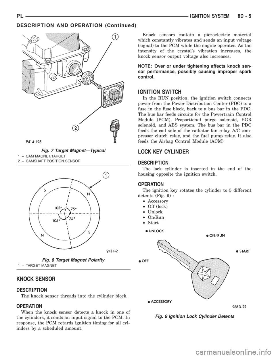
The ignition key rotates the cylinder to 5 different
detents (Fig. 9) :
²Accessory
²Off (lock)
²Unlock
²On/Run
²Start
Fig. 7 Target MagnetÐTypical
1 ± CAM MAGNET/TARGET
2 ± CAMSHAFT POSITION SENSOR
Fig. 8 Target Magnet Polarity
1 ± TARGET MAGNET
Fig. 9 Ignition Lock Cylinder Detents
PLIGNITION SYSTEM 8D - 5
DESCRIPTION AND OPERATION (Continued)