Page 293 of 365

yellowblue
6-36
9. Install the new bulb by inserting the smallest tab on
the bulb base into the matching notch in the
retaining ring. Turn the bulb a quarter
-turn
clockwise until it stops.
10. Reverse all steps to reinstall the headlamp
assembly. Then, check the lamps.
Headlamp Aiming
If your vehicle is damaged in an accident, the headlamp
aim may be affected. Aim adjustment to the low beam
may be necessary if it is difficult to see lane markers
(for horizontal aim), or if oncoming drivers flash their
high beams at you (for vertical aim). If you believe your
headlamps need to be re
-aimed, we recommend that you
take your vehicle to the dealer for service. However, it is
possible for you to re
-aim your headlamps by following
the procedure in the service manual for your vehicle.
NOTICE:
To make sure your headlamps are aimed
properly, read all the instructions before
beginning. Failure to follow these instructions
could cause damage to headlamp parts.
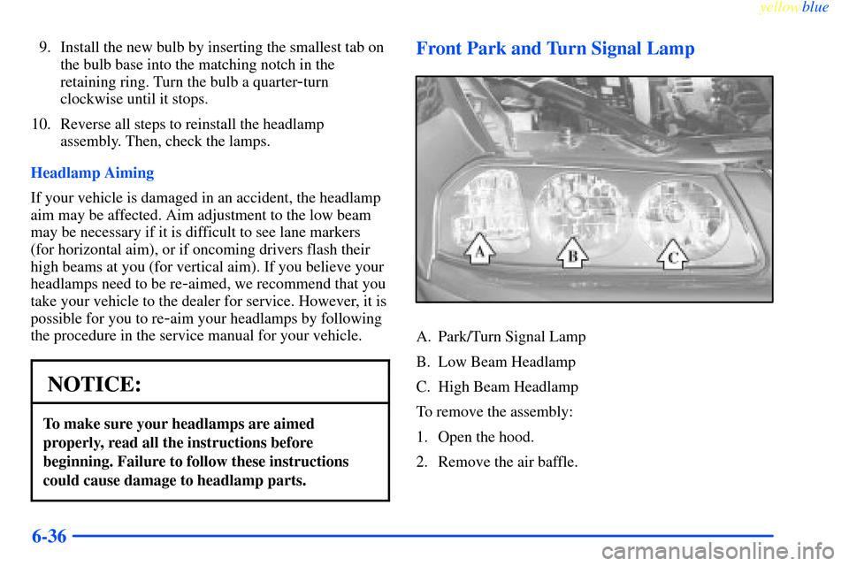
Front Park and Turn Signal Lamp
A. Park/Turn Signal Lamp
B. Low Beam Headlamp
C. High Beam Headlamp
To remove the assembly:
1. Open the hood.
2. Remove the air baffle.
Page 294 of 365
yellowblue
6-37
3. Remove the two headlamp fasteners by pulling
up on them.4. Gently pull the headlamp assembly away from the
vehicle and remove the electrical connector.
5. Remove the round dust caps to gain access
to the bulbs.
6. Turn the bulb counterclockwise and remove it from
the retaining ring by gently pulling it away from the
headlamp.
7. Remove the electrical connector from the bulb by
raising the lock tab and pulling the connector away
from the bulb's base.
8. Install the electrical connector to the bulb.
Page 295 of 365
yellowblue
6-38
9. Install the new bulb by inserting the smallest tab on
the bulb base into the matching notch in the
retaining ring. Turn the bulb a quarter
-turn
clockwise until it stops.
10. Reinstall the dust caps and reconnect the
electrical connector.
11. Install the headlamp assembly back to the vehicle.
12. Attach the air baffle.
13. Close the hood.
Fog Lamps (If Equipped)
1. Remove the T15 TORX� screw.
2. Pull out the lamp assembly.
3. Remove the old bulb. Do not discard! The
replacement number is printed on the bulb.
See ªReplacement Bulbsº in the Index for
more information.
4. Insert new bulb into the assembly.
5. Reinstall the lamps and screw.
Tail/Stop/Turn Signal Lamp
A. Rear Sidemarker Lamp
B. Tail/Stop/Turn Signal Lamp
To remove the rear lamp assembly:
1. Open the trunk. Remove the convenience net, if you
have one. Unhook the net from the upper wing nut.
Page 296 of 365
yellowblue
6-39
2. Remove the upper
(convenience net) wing
nut, if equipped.
3. Pull the carpet away from the rear of the vehicle.
4. Unscrew the two remaining wing nuts.5. Pull the assembly from the body carefully.
6. To remove a socket, press the tab, turn the socket
counterclockwise and pull it out.
7. Pull the bulb out. Do not twist it.
8. Push the new bulb into the socket.
9. Reinstall the socket in the assembly. Tighten the
socket by turning it clockwise.
10. Install the assembly and the two lower wing nuts.
11. Reinstall the carpeting.
12. Reinstall the upper (convenience net) wing nut and
convenience net, if equipped.
Page 297 of 365
yellowblue
6-40 Rear Sidemarker Lamp
A. Rear Sidemarker Lamp
B. Tail/Stop/Turn Signal Lamp
To remove the rear lamp assembly:
1. Open the trunk. Remove the convenience net if you
have one. Unhook the net from the upper wing nut.
2. Remove the upper
(convenience net) wing
nut, if equipped.
3. Pull the carpet away from the rear of the vehicle.
4. Unscrew the two remaining wing nuts.
5. Pull the assembly from the body carefully.
6. To remove the socket, turn the socket
counterclockwise and pull it out.
7. Pull the bulb out. Do not twist it.
8. Push the new bulb into the socket.
9. Replace the socket in the assembly. Tighten the
socket by turning it clockwise.
Page 298 of 365

yellowblue
6-41
10. Install the assembly and the two lower wing nuts.
11. Reinstall the carpeting.
12. Reinstall the upper (convenience net) wing nut
and convenience net, if equipped.
Back-Up Lamp
1. Open the trunk. The back-up lamp bulbs are in
the rear of the trunk lid.
2. Remove the nine wing nuts.
3. Pull the rear applique away from the vehicle.
4. To remove a socket press the tab, turn the socket
counterclockwise and pull it out.
5. Pull the bulb out. Do not twist it.
6. Push the new bulb into the socket.7. Reinstall the socket in the assembly. Tighten the
socket by turning it clockwise.
8. Reinstall the applique and the nine wing nuts.
Rear Courtesy Lamps
1. Remove the two access covers from the assist handle
assembly using a small coin.
2. Remove the old bulb from the small prongs
extending from the dome lamp base plate; hook the
new bulb onto the prongs.
3. Remove the two screws with a E8 TORX
� socket.
4. Pull the assist handle assembly out and remove
the old bulb.
5. Reverse Steps 1 through 3 to reassemble.
Page 319 of 365
yellowblue
6-62
Driver's Side Instrument Panel Fuse Block
Some fuses are in a fuse
block on the driver's side
of the instrument panel.
Pull off the cover labeled
FUSES to expose the fuses.
Circuit Relay Description
RETAINED
ACCESSORY
PWR RELAYRetained Accessory Power Relay
HEADLAMP
RELAYHeadlamp Relay
Page 320 of 365

yellowblue
6-63
Circuit
BreakerDescription
RETAINED
ACCESSORY
PWR BRKRPower Window, Sunroof Breaker
Mini Fuses Description
PCM/BCM/
CLSTRPowertrain Control Module,
Body Control Module,
Cluster (Ignition 0)
WSW Windshield Wipers,
Windshield Washer
PCM
(CRANK)Powertrain Control
Module (Crank)
CIG/AUX Accommodated
Device (Accessory)
BCM Body Control Module (Accessory)
SRS Supplemental Restraint System
ABS/PCM Anti
-Lock Brake System,
Powertrain Control Module,
Brake Switch, Crank Relay,
Canister Vent Solenoid
(Run, Crank)Mini Fuses Description
STOP Brake Lamps, Body Control
Module (Run, Crank)
TURN
SIGNALTurn Signal Flashers
CRUISE Cruise Control Steering
Column Controls
A/C CRUISE HVAC Temp Door Motors &
Module, Cruise Control Module
A/C FAN HVAC Blower
STR COL Steering Wheel Lighting
DR LK Body Control Module,
Door Lock Controls
PWR MIR Power Mirrors
CLSTR/BCM Cluster, Body Control Module,
Data Link Connector (Battery)
LH HTD
ST/BCMDriver's Heated Seat, Body
Control Module, Battery
Controlled Loads