2000 AUDI ALLROAD cooling
[x] Cancel search: coolingPage 7 of 306

TABLE OF CO
NTENTS----------------------------------------------
Cigar ette lighter I Socket ....... 181
Storage compartments
Steering wheel with
Audio controls .......••.... 0
Steering wheel with
radio and telephone equipment
in the steering wheel .
Mobile telephones and
CB radios ..
earphone ..•
Roof rack ... ..
I VEHICLE
OPERATION
The first 1,000 miles (1 500 km)-182
18 5
186
189 19 0
191
and afterwa rds ....... ....... .. 193
Operate your vehicle safely . . . . . 194
Operate your vehicle economically
and minimize pollution . . 195
Driving on rough roads or
rugged terrain . . . . . . . . . . 199
Braking . . . . . . . . . . . . . . . . . 201
Ele ctronic differential lock
(EDL) 204
6 Electronic
Stability Program
(ESP) .. .. .. .. .. .. .. .. .. 205
Driving with your quattro® . . . . . . 207
Trailer towing . . . . . . . . _ ... _ . . 208
I VEHICLE
CARE
Cleaning and protection 212
Fuel tank . . . . . . . .
222
Fuel supply . _ .... .. _ . . . . . . . . . . 225
Maintenance ..• •. .
Engine hood .
. . .
Engine compartment
Engine oil ..... ..... .
Engine cooling system
o •• •••
Power steering
Brake fluid ..
Battery ...
Air cleaner
Spark plugs
Belts . . . . .
. __ ..• .. ...
Windshield I
headlight washer container ..... 228
231
232
234
238
241
242
244 248
249
249
250 Wiper
blades
lires I Wheels
Difficult operating
conditions ...... . .
Additional accessories, Modifications and
Parts replacement ...... . .
I DO-IT-YOURSELF
SERVICE
First aid kit ....•.
Emergency
warning triangle . . . . . . . . .
Jack and tools ... .• . _ .. ..• .. ..
Spare wheel .. .. . .. ... . ..
Changing a wheel . . . • . . . . .
Fuses ........ .. . . . .. .. _ .. ..
Replacing bulbs
Installing I
replacing a radio
Emergency starting
Emergency towing with
commercial tow truck
Lifting vehicle .... . 251
252
262
262
263
263
264
266
267 274
277
277
278
281
283
Page 120 of 306

--------------------CONTROLS AND EQUIPMENT
Warning light
If the coolant warning light m the Auto
Check System (see page 141) flashes when
driving, the engine may be overheated be
cause of low coolant level.
Note
Do not install accessories (addi
tional lights or Insect screens. for
example) on top of the front bumper.
They may restrict engine cooling
and cause engine damage.
Always heed all WA RNINGS
on page 142 and 232. 5
- Fuel gauge
iU
The fuel gauge works when the ignition is
switched on.
The fuel tank capacity is approximately 18.5
gallons (70 liters).
When the needle reaches the red area
there is a reserve of about 2.4 U.S. gallon �
(9 liters) of fuel left in the tank. lime to re
fuel.
The fuel pump symbol in the instrument
cluster lights up as an additional reminder to
refuel.
Never run the tank completely dry. See also
page 222. 6
- Speedometer I odometer
Speedometer Refer to "Break-In Period" before driving
off see page 193.
The speedometer indicates the speed.
On U.S. models, the outer row of numbers
� larg ": numbers) indicates the vehicle speed
1n m1les per hour (mph). The inner row
(small numbers) indicates the vehicle
speed in kilometres per hour (km I h).
The arrangement of the instruments in the
c !uster may vary depending on engine ver
SIOn.
119
Page 142 of 306

--------------------CONTROLS AND
EQUIPMEN T
If there are one or more faults, the driver in
formation disappears about 15 seconds af
ter the engine has been started and the ap
propriate fault symbol appears in the
display.
If neither "OK" nor any other fault symbol
appear in the displa y, the auto-check sy
stem must itself be checked. Displays
In case of a malfunction or component fail
ure, the acoustic warning will sound and the
following symbols can appear.
Brake light
USA models:
Canada models: BRAKE
LIGHT
(@)
The following electrical components should
be checked, repaired or replaced, as neces
sary:
• Brake light bulbs
• Fuses
• All wiring connections Engine
coolant
temperature /level
If the light flashes, either the coolant ten:
perature is too high, or the coolant level1s
too low.
• If the light starts to f_lash, move
the vehicle a safe d1stance off
the road, stop the engine, depress
the emergency flasher switch, turn
off the engine and let it cool down.
Check coolant level. Top up as necessary
(see "Cooling system", page 238). ·
g Always heed all WA RNINGS
� on page 232.
141
Page 164 of 306

---------------------CONTROLS AND EQUIPMENT
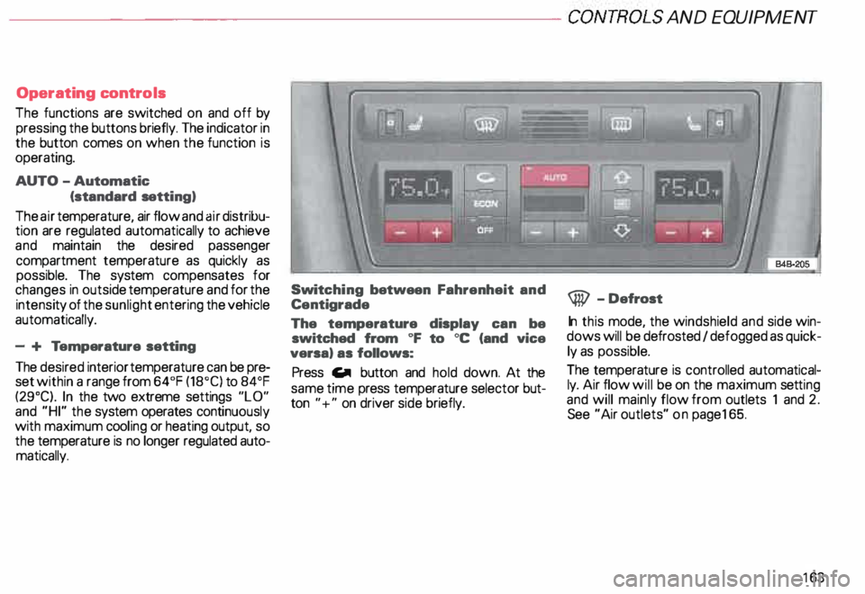
Operating controls
The functions are switched on and off by
pressing the buttons briefly. The indicator in
the button comes on when the function is
operating.
AUTO -Automatic
(standard setting)
The air temperature, air flow and air distribu
tion are regulated automatically to achieve
and maintain the desired passenger
compartment temperature as quickly as
possible. The system compensates for
changes in outside temperature and for the
intensi ty of the sunlight entering the vehicle
automatically.
- + Temperature setting
The desired interior temperature can be pre
set within a range from 64°F (18°C) to 84°F
(29°C). In the two extreme settings "LO"
and "HI" the system operates continuously
with maximum cooling or heating output, so
the temperature is no longer regulated auto
matically. Swit
ching between Fahrenheit and
Centigrade
The temperature display can be
switched from oF to oc (and vice
versa) as follows:
Press Gill button and hold down. At the
same time press temperature selector but
ton "+" on driver side briefly. @
-Defrost
In this mode, the windshield and side win
dows will be defrosted I defogged as quick
ly as possible.
The temperature is controlled automatical
ly. Air flow will be on the maximum setting
and will mainly flow from outlets 1 and 2.
See "Air outlets" on pag e165.
163
Page 166 of 306

---------------------CONTROLS
AND EQUIP MENT
Air outlets
Depending on the operating mode se
lected, the air flow to the outlets is con
trolled either automatically or man ually.
The illust ration shows the air outlets in and
around the dashboard.
The outlets deliver either heated or un
heated fresh air, or cooled air. I
848-902
1 - Outlets over full width of windshield
2 - Side window defroster I defogger
nozzles
3 - Side dashboard and rear console vents
4 - Center dashboard vents
5 - Footw all outlets Outlets
2, 3 and 4 can be opened or
closed separately with the respective
thumbwheel next to the outlets.
The direction of air delivery from these
outlets can be adjusted horizontally and
vert ically. The upper outlets (2) are not ad
justable.
Note
When the air conditioner is cooling the ve
hicle interior, the cool air mainly emerges
from outlets 3 and 4. To ensure adequate
cooling, these outlets should therefore nev
er be closed completely.
165
Page 168 of 306

---------------------CONTROLS AND
EQUIPMENT
General notes
• Vehicle heating is depend upon tne tem
perature of the engine coolant -therefore,
your vehicle interior will warm uponly when
the engine has reached its operating tem
perature.
When the ambient temperature is too low,
the fan only switches to high speed modes
when the coolant has reached a sufficiently
high temperature, or when the ® button
has been depressed.
• Keeping the air intake slots in front of the
windshield free from ice, snow and debris
helps to make sure that the climate control
system will work properly.
• When the air conditioner compressor is
on it reduces both the temperature and the
humid ity of the air inside the vehicle. This
prevents the windows from fogging up.
• The air conditioner works best with the
windows and power roof* closed. •
If the inside temperature is very high af
ter the vehicle has been parked in the sun,
open windows and allow the hot air to es
cape before switching on the air condi
tioner.
• The dust and pollen filter will prevent
dust and pollen etc. in the outside air from
entering the car. Switch to air recirculation
to prevent unpleasant fumes from entering
the vehicle.
If water drips under the
vehicle ...
At high outside temperatures and humidity,
condensation may drip from the evaporator.
This is normal and does not indicate a leak.
If the airflow is not cool ...
• At low ambient temperatures the air con
ditioner compressor switches off automati
cally. The compressor cannot be switc hed
on again in this case, even by pressing the
AUTO button. •
The air conditioner may switch itself off
temporarily to ensure sufficient engine
cooling when the engine is running at full
load.
The air conditioner will also be switched off
temporarily in the kick-down function. See
page 109.
• Check the air conditioning fuse on the
fuse p imel -see page 27 4. Have it replaced,
if necessary.
• If you suspect that the air conditioner is
damaged, for instance after an accident,
switch to the ECON and have the system
examined immediately for leaks or other
damage.
167
Page 209 of 306

VEHICLE OPERA
TION-----------------------
Trailer towing
Yo ur Audi was designed primarily for pas
senger transportat ion. The additional load
will affect durability, economy and perfor
mance.
Tra iler towing not only places more stress
on the vehicle, it also calls for more con
centration from the driver.
For this reasons, always follow the opera
ting and driving instructions given and use
common sense.
208 Te
chnical requirements
Tr ailer hitch
Use a weight-carrying hitch conforming to
the gross trailer weight. The hitch must be
suitable for your vehicle and trailer and
securely bolted to appropriate place on the
vehicle's chassis. Use only a trailer hitch
with removable ball mount. Always check
with the trailer hitch manufacturer to make
sure that you are using the correct hitch.
Do not use a bumper hitch.
The hitch must be installed in such a way
that it does not interfere with the impact-ab
sorbing bumper system. No modifications
should be made to the vehicle exhaust and
brake systems. From time to time, check
that all hitch mounting bolts remain secure
ly fastened. When
you are not towing a trailer, remove
the trailer hitch ball mount. This prevents
the hitch from causing damage should your
vehicle be struck from behind.
�W ARNING
When you are no longer towing a
trailer, remove the entire trailer
hitch. When doing so, seal all bolt
holes to prevent water and deadly
exhaust fumes from entering the
vehicle.
Engine cooling system
To wing a tr ailer make the engine work hard
er. It is important that the engine cooling
system be up to the job. Make sure that the
cooling system has enough fluid.
Page 239 of 306

VEHICLE CA
RE----------------------------------------------------
Engine cooling system
The cooling system is sealed and generally
requires little attention.
The cooling system has been filled at the
factory with a permanent coolant which
does not need to be changed. The coolant
consists of a mixture of water and the
man ufacturer's coolant additive G 12 ABD
-ant ifreeze on a glycol base with anti-corro
sion additives (50% for USA models; 60o/o
for Canadian models). This mixture assures
the necessary frost protection and protects
alloy components in the engine's cooling
system from corrosion and scaling. It also
raises the boiling point of the coolant.
Do not reduce the concentration of the cool
ant in the summer by adding plain water.
The proportion of coolant additive
must be at least 500fa but not more
than 600fa to maintain antifreeze protec
tion and cooling efficiency.
238 For
year-r ound driving, antifreeze is added at
the factory for temperatures down to:
-31 °F (-35 °C) USA
-40 °F (-40 °C) Canada.
g Always heed all WA RNINGS
E!!1 on page 232.
Never use eny coolant additive
other than our G12 ABD additive
(check label) for your vehicle. This
coolant additive is available at au
thorized Audi Dealers.
Other types of antifreeze can. above
all. significantly reduce corrosion
protection. The resulting corrosion
can cause a loss of coolant and
therefore serious engine damage. When
adding coolant additive to
your cooling system. please remem
ber:
Under no circumstances may G12
ABD be mixed with other coolant ad
ditives (for example G 11 ).
You can recognize G12 ABD in the
expansion tank by its red color. If
the liquid in the expansion tank is
brown, G 12 ABD has been mixed
with another coolant additive. In
this case. your vehicle's coolant
must be changed as soon as pos
sible.
Note
Mixing coolant additives can result
in serious malfunction or engine
damage!