Page 13 of 4592
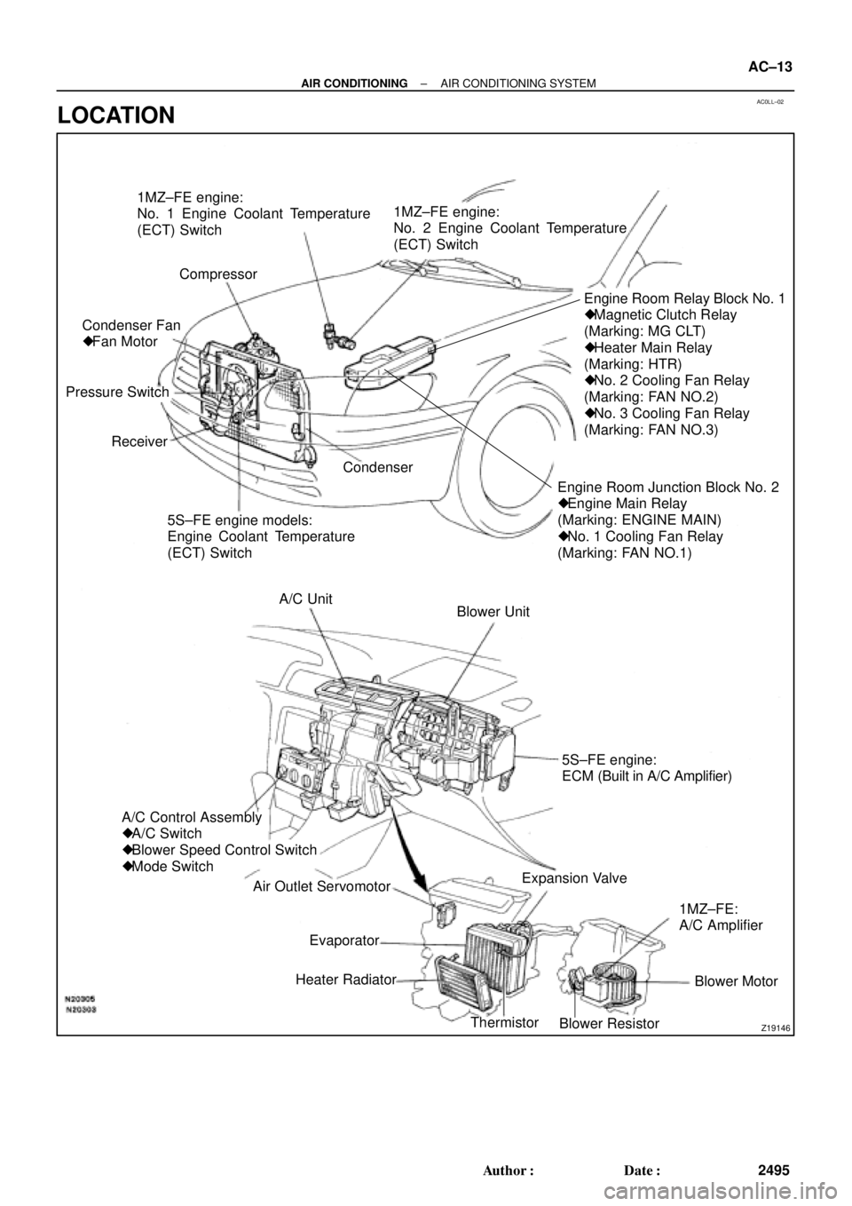
AC0LL±02
Z19146
1MZ±FE engine:
No. 1 Engine Coolant Temperature
(ECT) Switch
Compressor
Engine Room Junction Block No. 2
� Engine Main Relay
(Marking: ENGINE MAIN)
� No. 1 Cooling Fan Relay
(Marking: FAN NO.1)Engine Room Relay Block No. 1
� Magnetic Clutch Relay
(Marking: MG CLT)
� Heater Main Relay
(Marking: HTR)
� No. 2 Cooling Fan Relay
(Marking: FAN NO.2)
� No. 3 Cooling Fan Relay
(Marking: FAN NO.3)
5S±FE engine models:
Engine Coolant Temperature
(ECT) Switch Receiver Pressure SwitchCondenser Fan
� Fan Motor1MZ±FE engine:
No. 2 Engine Coolant Temperature
(ECT) Switch
Condenser
Blower Unit A/C Unit
A/C Control Assembly
� A/C Switch
� Blower Speed Control Switch
� Mode Switch
Air Outlet Servomotor
Heater Radiator
Thermistor
Blower ResistorBlower Motor 1MZ±FE:
A/C Amplifier Expansion Valve5S±FE engine:
ECM (Built in A/C Amplifier)
Evaporator
± AIR CONDITIONINGAIR CONDITIONING SYSTEM
AC±13
2495 Author�: Date�:
LOCATION
Page 14 of 4592

AC21T±01
AC±14
± AIR CONDITIONINGTROUBLESHOOTING
2496 Author�: Date�:
TROUBLESHOOTING
PROBLEM SYMPTOMS TABLE
Use the table below to help you find the cause of the problem. The numbers indicate the priority of the likely
cause of the problem. Check each part in order. If necessary, replace these parts.
SymptomSuspect AreaSee page
No blower operation
4. HTR Fuse
5. Heater main relay
6. Blower motor
7. Blower resistor
8. Blower speed control switch
9. Wire harness±
AC±70
AC±63
AC±64
AC±84
±
No air temperature control1. Engine coolant volume
2. A/C control assembly±
AC±80
No air inlet control1. A/C control assemblyAC±80
No air outlet control
1. HTR Fuse
2. Air outlet servomotor
3. Mode switch±
AC±65
AC±84
No compressor operation
1. Refrigerant volume
2. A.C Fuse
3. HTR Fuse
4. Magnetic clutch relay
5. Magnetic clutch
6. Compressor
7. Pressure switch
8. Heater main relay
9. Blower speed control switch
10.A/C switch
11. *1 ECM
*
2 A/C amplifier
12.Wire harness
AC±3
±
±
AC±71
AC±39
AC±39
AC±67
AC±70
AC±84
AC±84
DI±218
AC±88
±
No compressor operates intermittently
1. Refrigerant volume
2. Condenser fan
3. Pressure switch
4. *1 ECM
*2 A/C amplifier
5. Thermistor
6. Wire harnessAC±3
AC±74
AC±67
DI±218
AC±88
AC±24
±
No cool air comes out
1. Refrigerant volume
2. Refrigerant pressure
3. Drive belt
4. Compressor lock sensor
5. Magnetic clutch
6. Compressor
7. Pressure switch
8. Thermistor
9. A/C switch
10.*1 ECM
*2 A/C amplifier
11. Wire harnessAC±3
AC±3
AC±16
AC±16
AC±39
AC±39
AC±67
AC±24
AC±84
DI±218
AC±88
±
Page 15 of 4592
± AIR CONDITIONINGTROUBLESHOOTING
AC±15
2497 Author�: Date�:
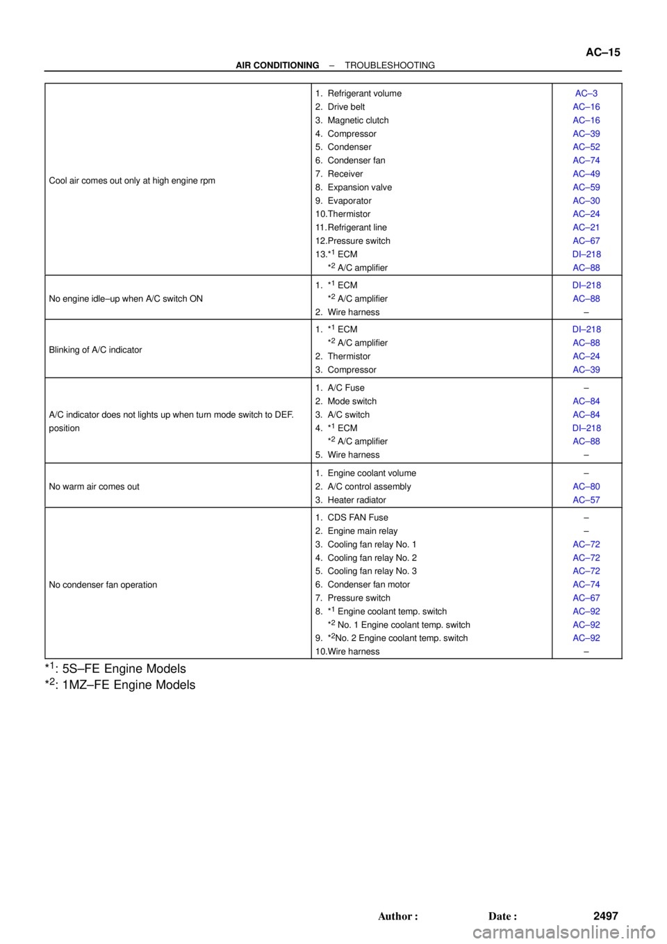
Cool air comes out only at high engine rpm
1. Refrigerant volume
2. Drive belt
3. Magnetic clutch
4. Compressor
5. Condenser
6. Condenser fan
7. Receiver
8. Expansion valve
9. Evaporator
10.Thermistor
11. Refrigerant line
12.Pressure switch
13.*
1 ECM
*2 A/C amplifier
AC±3
AC±16
AC±16
AC±39
AC±52
AC±74
AC±49
AC±59
AC±30
AC±24
AC±21
AC±67
DI±218
AC±88
No engine idle±up when A/C switch ON
1. *1 ECM
*2 A/C amplifier
2. Wire harness
DI±218
AC±88
±
Blinking of A/C indicator
1. *1 ECM
*2 A/C amplifier
2. Thermistor
3. Compressor
DI±218
AC±88
AC±24
AC±39
A/C indicator does not lights up when turn mode switch to DEF.
position
1. A/C Fuse
2. Mode switch
3. A/C switch
4. *
1 ECM
*2 A/C amplifier
5. Wire harness
±
AC±84
AC±84
DI±218
AC±88
±
No warm air comes out
1. Engine coolant volume
2. A/C control assembly
3. Heater radiator±
AC±80
AC±57
No condenser fan operation
1. CDS FAN Fuse
2. Engine main relay
3. Cooling fan relay No. 1
4. Cooling fan relay No. 2
5. Cooling fan relay No. 3
6. Condenser fan motor
7. Pressure switch
8. *
1 Engine coolant temp. switch
*2 No. 1 Engine coolant temp. switch
9. *2No. 2 Engine coolant temp. switch
10.Wire harness
±
±
AC±72
AC±72
AC±72
AC±74
AC±67
AC±92
AC±92
AC±92
±
*1: 5S±FE Engine Models
*
2: 1MZ±FE Engine Models
Page 34 of 4592
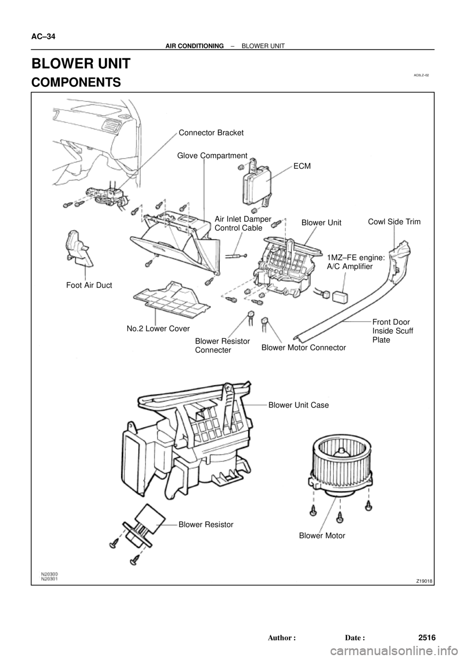
AC0LZ±02
Z19018
Connector Bracket
Glove Compartment
ECM
Foot Air Duct
No.2 Lower CoverBlower UnitCowl Side Trim
Blower Motor Connector
Blower Motor Blower Unit Case Air Inlet Damper
Control Cable
1MZ±FE engine:
A/C Amplifier
Front Door
Inside Scuff
Plate
Blower Resistor
Connecter
Blower Resistor AC±34
± AIR CONDITIONINGBLOWER UNIT
2516 Author�: Date�:
BLOWER UNIT
COMPONENTS
Page 35 of 4592
AC0M0±02
± AIR CONDITIONINGBLOWER UNIT
AC±35
2517 Author�: Date�:
REMOVAL
1. REMOVE COWL SIDE TRIM
2. REMOVE FRONT DOOR INSIDE PLATE LH
3. REMOVE NO. 2 LOWER COVER
4. REMOVE GLOVE COMPARTMENT
5. REMOVE ECM
(a) Disconnect the connectors.
(b) Remove the 2 nuts and ECM.
6. DISCONNECT AIR INLET DAMPER CONTROL CABLE
HINT:
At the in time of installation, please refer to following item.
After connection, inspect the air inlet control lever operation.
(See page AC±87).
7. REMOVE A/C AMPLIFIER.
(a) Disconnect the connector.
(b) Release the 2 claws and pull out the amplifier.
8. REMOVE CONNECTOR BRACKET SET SCREWS
9. REMOVE BLOWER UNIT
(a) Disconnect the connector.
(b) Disconnect the thermistor connector clamp.
(c) Remove the 2 screws, bolt and nut, then remove the blower unit.
Page 158 of 4592

INTRODUCTIONGLOSSARY OF SAE AND TOYOTA TERMS ±
IN±6
GLOSSARY OF SAE AND TOYOTA TERMS
This glossary lists all SAE±J1930 terms and abbreviations used in this manual in compliance with SAE
recommendations, as well as their Toyota equivalents.
SAE
ABBREVIATIONSSAE TERMSTOYOTA TERMS
( )±±ABBREVIATIONS
A/CAir ConditioningAir Conditioner
ACLAir CleanerAir Cleaner
AIRSecondary Air InjectionAir Injection (AI)
APAccelerator Pedal±
B+Battery Positive Voltage+B, Battery Voltage
BAROBarometric Pressure±
CACCharge Air CoolerIntercooler
CARBCarburetorCarburetor
CFIContinuous Fuel Injection±
CKPCrankshaft PositionCrank Angle
CLClosed LoopClosed Loop
CMPCamshaft PositionCam Angle
CPPClutch Pedal Position±
CTOXContinuous Trap Oxidizer±
CTPClosed Throttle Position±
DFIDirect Fuel Injection (Diesel)Direct Injection (DI)
DIDistributor Ignition±
DLC1
DLC2
DLC3Data Link Connector 1
Data Link Connector 2
Data Link Connector 31: Check Connector
2: Toyota Diagnosis Communication Link (TDCL)
3: OBD@@@@@: [g 2] Diagnostic Connector
DTCDiagnostic Trouble CodeDiagnostic Code
DTMDiagnostic Test Mode±
ECLEngine Control Level±
ECMEngine Control ModuleEngine ECU (Electronic Control Unit)
ECTEngine Coolant TemperatureCoolant Temperature, Water Temperature (THW)
EEPROMElectrically Erasable Programmable Read Only
MemoryElectrically Erasable Programmable Read Only Memory
(EEPROM),
Erasable Programmable Read Only Memory(EPROM)
EFEEarly Fuel EvaporationCold Mixture Heater (CMH), Heat Control Valve (HCV)
EGRExhaust Gas RecirculationExhaust Gas Recirculation (EGR)
EIElectronic IgnitionToyota Distributorless Ignition (TDI)
EMEngine ModificationEngine Modification (EM)
EPROMErasable Programmable Read Only MemoryProgrammable Read Only Memory (PROM)
EVAPEvaporative EmissionEvaporative Emission Control (EVAP)
FCFan Control±
FEEPROMFlash Electrically Erasable Programmable
Read Only Memory±
FEPROMFlash Erasable Programmable Read Only Memory±
FFFlexible Fuel±
FPFuel PumpFuel Pump
GENGeneratorAlternator
GNDGroundGround (GND)
HO2SHeated Oxygen SensorHeated Oxygen Sensor (HO2S)
IN016±02
Page 176 of 4592
AUTOMATIC TRANSAXLEOPERATION ±
AX±6
2. HYDRAULIC CONTROL SYSTEM
The hydraulic control system is composed of the oil pump, the valve body, the solenoid valves, the accu-
mulators, the clutches and brakes, and the governor valve as well as the fluid passages which connect
all of these components.
Based on the hydraulic pressure created by the oil pump, the hydraulic control system governs the hy-
draulic pressure acting on the torque converter clutch, clutches and brakes in accordance with the ve-
hicle driving conditions.
There are three solenoid valves on the valve body.
The No.1 and No.2 solenoid valves are turned on and off by signals from the ECM to operate the shift
valves and change the gear shift position.
The No.3 solenoid valve is operated by signals from the ECM to engage or disengage the lock±up
clutch of the torque converter.
Page 177 of 4592
AUTOMATIC TRANSAXLEOPERATION ±
AX±7
2. ELECTRONIC CONTROL SYSTEM
The electronic control system for controlling the shift timing and the operation of the lock±up clutch is
composed of the following 3 parts:
(a) Sensors: These sense the vehicle speed and throttle position and send this data to the ECM in the form
of electronic signals.
(b) ECM: This determines the shift and lock±up timing based upon the signals from the sensors.
(c) Actuators: Solenoid valves divert hydraulic pressure from one circuit of the hydraulic control unit to
another, thus controlling shifting and lock±up timing.