Page 3655 of 4592

TSB
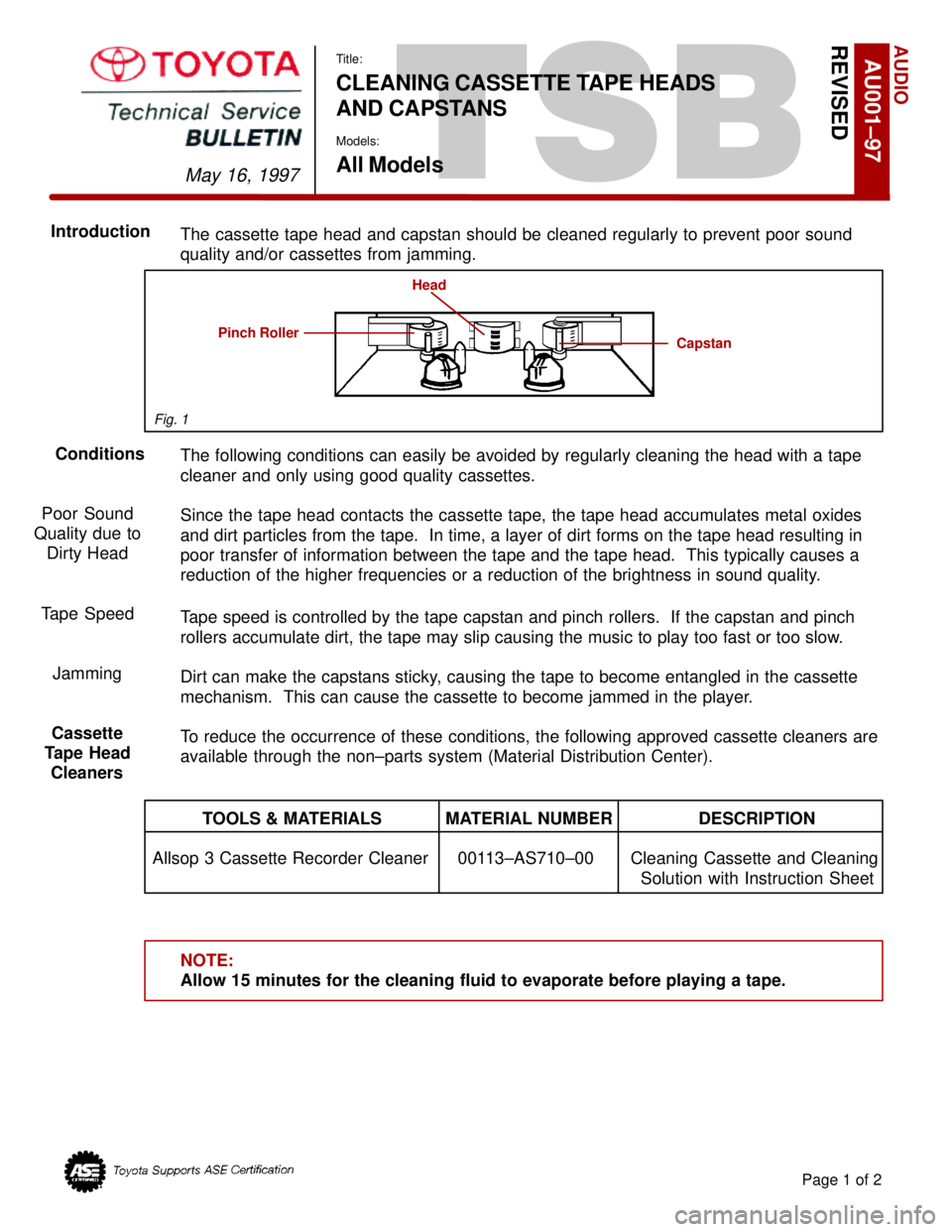
The cassette tape head and capstan should be cleaned regularly to prevent poor sound
quality and/or cassettes from jamming.
The following conditions can easily be avoided by regularly cleaning the head with a tape
cleaner and only using good quality cassettes.
Since the tape head contacts the cassette tape, the tape head accumulates metal oxides
and dirt particles from the tape. In time, a layer of dirt forms on the tape head resulting in
poor transfer of information between the tape and the tape head. This typically causes a
reduction of the higher frequencies or a reduction of the brightness in sound quality.
Tape speed is controlled by the tape capstan and pinch rollers. If the capstan and pinch
rollers accumulate dirt, the tape may slip causing the music to play too fast or too slow.
Dirt can make the capstans sticky, causing the tape to become entangled in the cassette
mechanism. This can cause the cassette to become jammed in the player.
To reduce the occurrence of these conditions, the following approved cassette cleaners are
available through the non±parts system (Material Distribution Center).
TOOLS & MATERIALS MATERIAL NUMBER DESCRIPTION
Allsop 3 Cassette Recorder Cleaner 00113±AS710±00 Cleaning Cassette and Cleaning
Solution with Instruction Sheet
NOTE:
Allow 15 minutes for the cleaning fluid to evaporate before playing a tape.
AUDIO
May 16, 1997
Title:
CLEANING CASSETTE TAPE HEADS
AND CAPSTANS
Models:
All Models
Page 1 of 2
AU001±97REVISED
Conditions Introduction
Poor Sound
Quality due to
Dirty Head
Tape Speed
Jamming
Cassette
Tape Head
Cleaners
Capstan
Head
Pinch Roller
Fig. 1
Page 3656 of 4592

CLEANING CASSETTE TAPE HEADSAND CAPSTANS ± AU001±97 (Revised) May 16, 1997
The following precautions should be taken to keep cassettes in good condition:
1. Remove the cassette from the player when the cassette is not in use.
2. Store the cassette in its case.
3. Store the cassette in a cool, dry area away from direct sunlight and magnetic
components such as speakers.
4. Avoid touching the tape itself. This could result in poor sound quality or sound drop out.
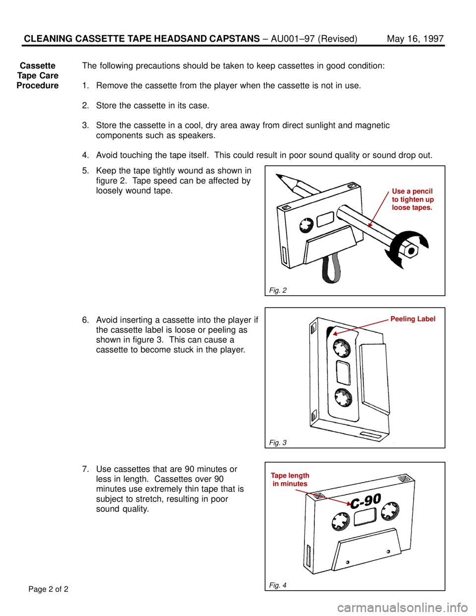
5. Keep the tape tightly wound as shown in
figure 2. Tape speed can be affected by
loosely wound tape.
6. Avoid inserting a cassette into the player if
the cassette label is loose or peeling as
shown in figure 3. This can cause a
cassette to become stuck in the player.
7. Use cassettes that are 90 minutes or
less in length. Cassettes over 90
minutes use extremely thin tape that is
subject to stretch, resulting in poor
sound quality.
Page 2 of 2
Cassette
Tape Care
Procedure
Peeling Label
Use a pencil
to tighten up
loose tapes.
Tape length
in minutes
Fig. 2
Fig. 3
Fig. 4
Page 4017 of 4592

B HOW TO USE THIS MANUAL
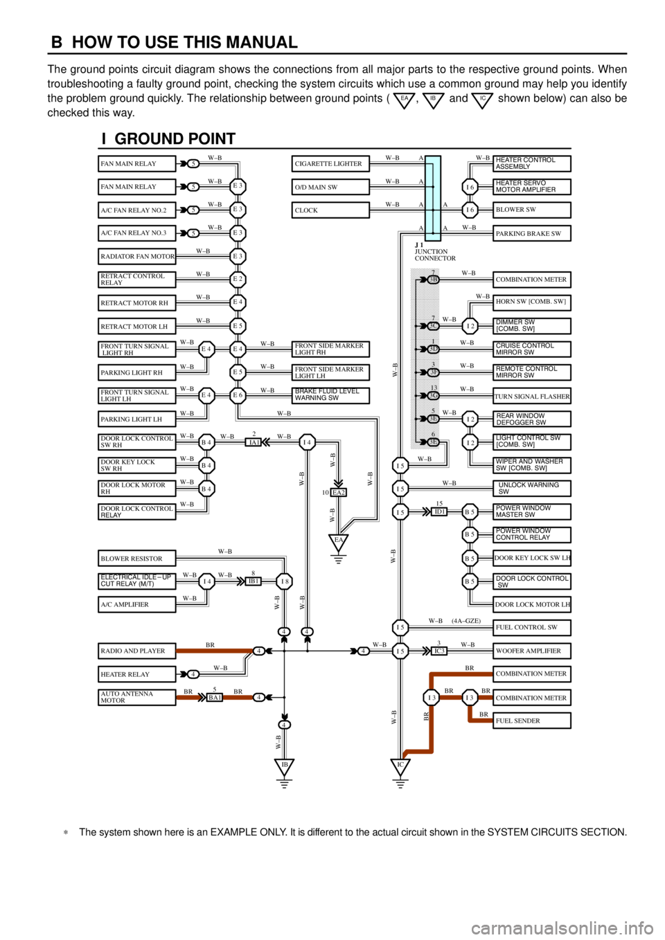
The ground points circuit diagram shows the connections from all major parts to the respective ground points. When
troubleshooting a faulty ground point, checking the system circuits which use a common ground may help you identify
the problem ground quickly. The relationship between ground points (
EA, IB and IC shown below) can also be
checked this way.
���� ���� ���� ���� ���� ���� ���� ���� ���� ���� ���� ���� ���� ���� ���� ���� ���� ���� ����
I GROUND POINT
FAN MAIN RELAY
FAN MAIN RELAY
A/C FAN RELAY NO.2
A/C FAN RELAY NO.3
RADIATOR FAN MOTOR
RETRACT CONTROL
RELAY
RETRACT MOTOR RH
RETRACT MOTOR LH
FRONT TURN SIGNAL
LIGHT RH
PARKING LIGHT RH
FRONT TURN SIGNAL
LIGHT LH
PARKING LIGHT LH
DOOR LOCK CONTROL
SW RH
DOOR KEY LOCK
SW RH
DOOR LOCK MOTOR
RH
BLOWER RESISTOR
A/C AMPLIFIER
RADIO AND PLAYER
HEATER RELAY
AUTO ANTENNA
MOTOR
BLOWER SW
PARKING BRAKE SW
COMBINATION METER
HORN SW [COMB. SW]
TURN SIGNAL FLASHER
DOOR KEY LOCK SW LH
DOOR LOCK MOTOR LH
FUEL CONTROL SW
WOOFER AMPLIFIER
COMBINATION METER
COMBINATION METER
FUEL SENDER
CIGARETTE LIGHTER
O/D MAIN SW
CLOCK
5
5
5
5
4
4
4
4
4BA15
IB18
EA2 10
3E5
3E
6 3G
13 3F
3 3D
1 3B
7
ID115
IC33
IA12
E 3
A
A AW±B
W±BW±B W±B
W±B W±B
W±B
W±B
W±B
W±B
W±B
W±B
W±B
W±B
W±B W±BW±B W±B W±B W±B
W±B W±B
W±BW±B
W±B
W±B
W±B W±B
W±B
BR
W±B
BR BRW±BW±B
W±B
W±B
W±B
W±B
W±B
W±B
W±B
W±B
W±B W±B
W±B
W±B
W±B
W±B
BR W±B
BR BR
BR W±B W±BW±B
W±BW±BBR W±B (4A±GZE)
W±B A A A
I 6
I 6
I 2
I 2
I 2
B 5I 5
I 5
I 5
B 5
B 5
B 5
I 5
I 5
I 3I 3
E 3
E 3
E 3
E 2
E 4
E 5
E 4
E 5
E 6E 4
E 4
B 4
EAI 4
B 4
B 4
I 4I 8
IBIC
3C7
4
JUNCTION
CONNECTOR J 1
4
DOOR LOCK CONTROL
RELAY
ELECTRICAL IDLE-UP
CUT RELAY (M/T)FRONT SIDE MARKER
LIGHT RH
FRONT SIDE MARKER
LIGHT LH
BRAKE FLUID LEVEL
WARNING SW
UNLOCK WARNING
SW WIPER AND WASHER
SW [COMB. SW] LIGHT CONTROL SW
[COMB. SW] HEATER CONTROL
ASSEMBLY
HEATER SERVO
MOTOR AMPLIFIER
DIMMER SW
[COMB. SW]
CRUISE CONTROL
MIRROR SW
REAR WINDOW
DEFOGGER SW
POWER WINDOW
MASTER SW
POWER WINDOW
CONTROL RELAY
DOOR LOCK CONTROL
SW
REMOTE CONTROL
MIRROR SW
*The system shown here is an EXAMPLE ONLY. It is different to the actual circuit shown in the SYSTEM CIRCUITS SECTION.
Page 4040 of 4592

G
Position of Parts in Instrument Panel
J 1 Junction Connector
J 2 Junction Connector
J 3 Junction Connector
J 4 Junction Connector
J 5 Junction Connector
J 6 Junction Connector
J 7 Junction Connector
J 8 Junction Connector
J 9 Junction Connector
J 10 Junction Connector
J 11 Junction Connector
J 12 Junction Connector
J 13 Junction Connector
J 14 Junction Connector
J 15 Junction Connector
J 16 Junction Connector
J 17 Junction Connector
J 18 Junction Connector
J 19 Junction Connector
J 20 Junction Connector
J 21 Junction Connector
J 22 Junction Connector
J 23 Junction Connector
J 24 Junction Connector
J 25 Junction Connector
J 26 Junction ConnectorJ 27 Junction Connector
J 28 Junction Connector
J 29 Junction Connector
J 30 Junction Connector
J 31 Junction Connector
J 32 Junction Connector
K 1 Key Interlock Solenoid
O 2 O/D Main SW and A/T Shift Lever Illumination
P 3 Parking Brake SW
P 4 Power Outlet
R 2 Radio and Player
R 3 Radio and Player
R 4 Rear Window Defogger SW
R 5 Remote Control Mirror SW
R 6 Rheostat
S 3 Shift Lock ECU
S 4 Stop Light SW
T 2 Turn Signal Flasher
U 1 Unlock Warning SW
Page 4088 of 4592
IE 3 2A 10
B 5
12
A 13
A
A
BG B
B
W±B W± BW±G
G
BJUNCTION
CONNECTOR J 4 2 1 A AAAAAAA
B A B A
B E
B EA D
A D
A D2 3
31 1
RHEOSTAT R 6
GLOVE BOX LIGHT AND SW
G 3 A/T SHIFT LEVER ILLUMINATION
[O/D MAIN SW] O 2
COMBINATION METER ILLUMINATION
[COMB. METER] C12
G
G
G
G
G G
G HAZARD SW H 5
G W± B
G
ET
ILL B
B B
G
J28
JUNCTION
CONNECTORB A, J29
R 2
RADIO AND PLAYERA B, R 3
J16
JUNCTION
CONNECTORB A, J17
Page 4143 of 4592
RADIO AND PLAYER
2K 11 1H3
1G 61W 5
A 4A3
B 3 B 1 A 6 A 2 A 7A1A5B2B6
ID1 9ID11IL19IL11IC19IC13IC110 IC14
111 1222 2
IG
L±Y L±Y L±Y
GR BR
P
V
LG
L
B
Y
R
W WRY
BL LGV P BR
20A
RADIO
NO. 17. 5A
RAD±NO. 2 FROM POWER SOURCE SYSTEM (
SEE PAGE 44)
GND FL+ FL± FR+ FR± RL+ RL± RR+ RR±BU +B ACC +B
GR
FRONT DOOR
SPEAKER LHFRONT DOOR
SPEAKER RHREAR SPEAKER
LHREAR SPEAKER
RH F15
F16 R11 R12R 2
RADIO AND PLAYERA B, R 3 B BA
AJUNCTION
CONNECTOR J16
Page 4144 of 4592

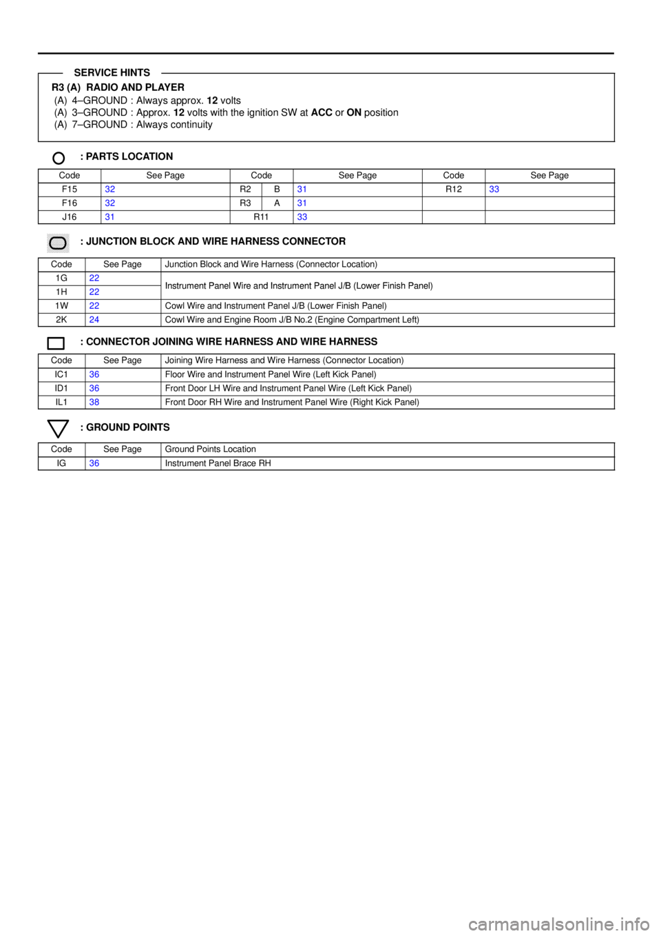
R3 (A) RADIO AND PLAYER
(A) 4±GROUND : Always approx. 12 volts
(A) 3±GROUND : Approx. 12 volts with the ignition SW at ACC or ON position
(A) 7±GROUND : Always continuity
: PARTS LOCATION
CodeSee PageCodeSee PageCodeSee Page
F1532R2B31R1233
F1632R3A31
J1631R1133
������ ���: JUNCTION BLOCK AND WIRE HARNESS CONNECTOR
CodeSee PageJunction Block and Wire Harness (Connector Location)
1G22Instrument Panel Wire and Instrument Panel J/B (Lower Finish Panel)1H22Instrument Panel Wire and Instrument Panel J/B (Lower Finish Panel)
1W22Cowl Wire and Instrument Panel J/B (Lower Finish Panel)
2K24Cowl Wire and Engine Room J/B No.2 (Engine Compartment Left)
: CONNECTOR JOINING WIRE HARNESS AND WIRE HARNESS
CodeSee PageJoining Wire Harness and Wire Harness (Connector Location)
IC136Floor Wire and Instrument Panel Wire (Left Kick Panel)
ID136Front Door LH Wire and Instrument Panel Wire (Left Kick Panel)
IL138Front Door RH Wire and Instrument Panel Wire (Right Kick Panel)
: GROUND POINTS
CodeSee PageGround Points Location
IG36Instrument Panel Brace RH
SERVICE HINTS
Page 4162 of 4592
(
E04)
(
E01)
(
E02)
(
E03)
HEATED OXYGEN
SENSOR
A/C MAGNETIC
CLUTCH AND
LOCK SENSOR COMBINATION
METER
IGNITION COIL AND
IGNITER NO. 1
IGNITION COIL AND
IGNITER NO. 2
DATA LINK
CONNECTOR 1
DATA LINK
CONNECTOR 2
DATA LINK
CONNECTOR 3ENGINE
CONTROL
MODULE IH13
A
A
EC A
EC
I 4 IG212
B B
B B A C
A CIG36
IJ210AA
A BR
BR
BR
BRBR
BR
BR
BR
BR BR
BR BR
BR BR BR BR
BR
BR BRBR
BR
A
JUNCTION
CONNECTOR J18
(
ET)
(
SG)
J 6
JUNCTION
CONNECTORB A, J 7(
E1) IG13
ENGINE CONTROL
MODULEBR A IDLE AIR
CONTROL VALVEW±B
W± B
BR
JUNCTION
CONNECTOR J20
(
ES)
W±B W±B
BRBR
W± B W±B
BL IJ 6
BB1 B 2IG
DOOR LOCK MOTOR
AND DOOR UNLOCK
DETECTION SW
REAR RH RADIO AND PLAYERCOMBINATION
METER (
E05)