Page 2370 of 4592
F00172
EC BRA
ABR
3
16 DLC1
Ts E
1
R±Y8
R±Y8
TsABS ECU
J20
J/C
BRA
ABR
3
16 DLC1
Ts E
1
R±Y
IG38
R±Y
A148
TsABS ECU
AB0119S08096
F00446DLC1 DLC1
DLC1
DLC1DLC1
Ts
DLC1 E1
ON
DI±218
± DIAGNOSTICSANTI±LOCK BRAKE SYSTEM
Ts Terminal Circuit
CIRCUIT DESCRIPTION
The sensor check circuit detects abnormalities in the speed sensor signal which cannot be detected with
the DTC check.
Connecting terminals Ts and E
1 of the DLC1 in the engine compartment starts the check.
WIRING DIAGRAM
INSPECTION PROCEDURE
1 Check voltage between terminals Ts and E1 of DLC1.
CHECK:
(a) Turn the ignition switch ON.
(b) Measure voltage between terminals Ts and E
1 of DLC1.
OK:
Voltage: 10 ± 14 V
OK If ABS warning light does not blink even after Ts
and E
1 are connected, the ECU may be defec-
tive.
NG
DI03S±04
Page 2371 of 4592
± DIAGNOSTICSANTI±LOCK BRAKE SYSTEM
DI±219
2 Check for open and short circuit in harness and connector between ABS ECU
and DLC1, DLC1 and body ground (See page IN±29).
NG Repair or replace harness or connector.
OK
Check and replace ABS ECU.
Page 2372 of 4592
F00071
DI±220
± DIAGNOSTICSANTI±LOCK BRAKE SYSTEM
Check for Fluid Leakage
Check for fluid leakage from actuator or hydraulic lines.
DI03T±04
Page 2470 of 4592

DI08G±09
CRUISE CONTROL SYSTEM Check Sheet
Inspector 's name:
Customer 's Name
Date VehicleRegistration No.
Registration Year
Frame No.
Odometer Reading / /km
Mile
Condition of
Problem Occurrence
Date of Problem
How Often does
Occurrence
Problem Occurs
Vehicle Speed when
Problem Occurred / /
Continuous Intermittent ( Times a day)
km
Mile Brought in
Auto cancel
occurs� Driving condition
� City driving � Freeway � Up hill � Down hill
� After cancel occurred, did the driver activate cruise control
again?
� Yes � No
� Cancel does not
occur� With brake ON
� Except D position shift � At 40 km/h (25 mph) or less
� When control SW turns to CANCEL position
� Cruise control
malfunction� Slip to acceleration side
� Slip to deceleration side
� Hunting occurs
� O/D cut off does not occur
� O/D does not return
� Switch
malfunction� SET � ACCEL � COAST � RESUME � CANCEL
�
� Remains ON � Does not light up � Blinking Symptoms
DTC Check1st Time2nd Time
� Normal Code � Malfunction Code (Code )
� Normal Code � Malfunction Code (Code ) DI±318
± DIAGNOSTICSCRUISE CONTROL SYSTEM
CUSTOMER PROBLEM ANALYSIS CHECK
Page 2474 of 4592

N17520
N17520
DI±322
± DIAGNOSTICSCRUISE CONTROL SYSTEM
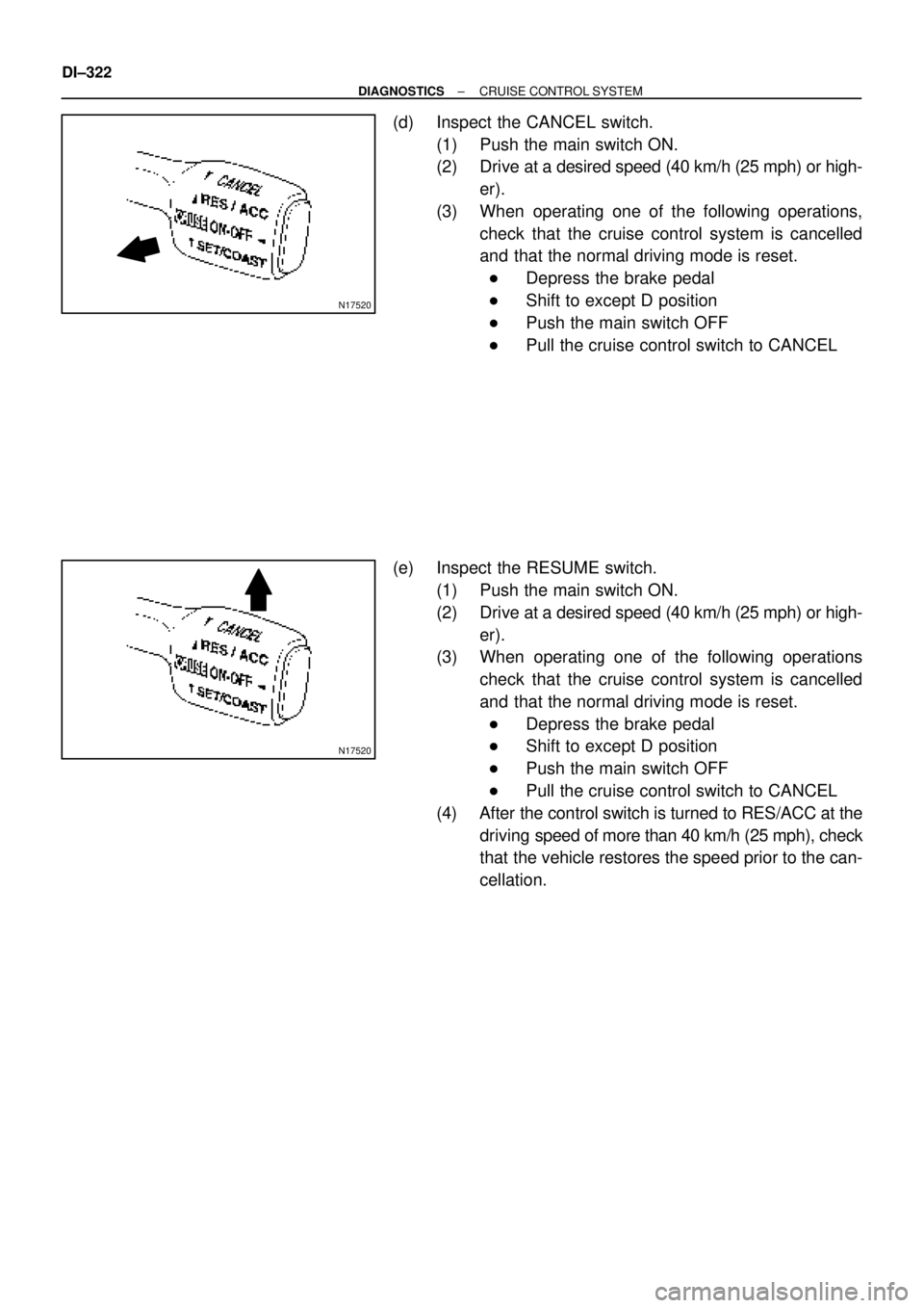
(d) Inspect the CANCEL switch.
(1) Push the main switch ON.
(2) Drive at a desired speed (40 km/h (25 mph) or high-
er).
(3) When operating one of the following operations,
check that the cruise control system is cancelled
and that the normal driving mode is reset.
�Depress the brake pedal
�Shift to except D position
�Push the main switch OFF
�Pull the cruise control switch to CANCEL
(e) Inspect the RESUME switch.
(1) Push the main switch ON.
(2) Drive at a desired speed (40 km/h (25 mph) or high-
er).
(3) When operating one of the following operations
check that the cruise control system is cancelled
and that the normal driving mode is reset.
�Depress the brake pedal
�Shift to except D position
�Push the main switch OFF
�Pull the cruise control switch to CANCEL
(4) After the control switch is turned to RES/ACC at the
driving speed of more than 40 km/h (25 mph), check
that the vehicle restores the speed prior to the can-
cellation.
Page 2475 of 4592

N17520
(1)
(2)
(1)
No.Operation MethodCRUISE MAIN Indicator Light
Blinking PatternDiagnosis
1 Turn SET/COAST switch ON
2Turn RES/ACC switch ON
3Turn CANCEL switch ON
Turn stop light switch ON
Depress brake pedal
Turn PNP switch OFF
(Shift to except D position)
4Drive at about 40 km/h
(25 mph)or higher
Drive at about 40 km/h
(25 mph) or below
LightON
OFF
LightON
OFF
LightON
OFFSwitch ON
Switch OFF
LightON
OFFSwitch OFF
Switch ONSET/COAST switch circuit
is normal
RES/ACC switch circuit
is normal
CANCEL switch circuit
is normal
Stop light switch circuit
is normal
PNP switch circuit is
normal
Vehicle Speed Sensor is
normal
LightON
OFF LightON
OFF
1sec.
0.25 sec.0.25 sec.
± DIAGNOSTICSCRUISE CONTROL SYSTEM
DI±323
5. INPUT SIGNAL CHECK
HINT:
(1): For check No.1 ± No.3
�Turn ignition switch ON.
(2): For check No.4
�Jack up the vehicle.
�Start the engine.
�Shift to D position.
(a) Pull the control switch to SET/COAST or RES/ACC posi-
tion and hold it down or up (1).
(b) Push the main switch ON (2).
(c) Check that the CRUISE MAIN indicator light blinks twice
or 3 times repeatedly after 3 seconds.
(d) Turn the SET/COAST or RES/ACC switch OFF.
(e) Operate each switch as listed in the table below.
(f) Read the blinking pattern of the CRUISE MAIN indicator
light.
(g) After performing the check, turn the main switch OFF.
HINT:
When 2 or more signals are input to the ECU, the lowest num-
bered code will be displayed first.
Page 2478 of 4592

DI1KT±07
I00293
C16
DI±326
± DIAGNOSTICSCRUISE CONTROL SYSTEM
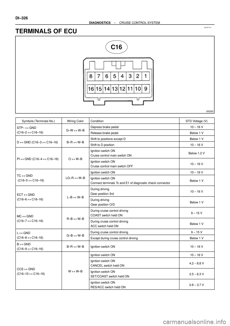
TERMINALS OF ECU
Symbols (Terminals No.)Wiring ColorConditionSTD Voltage (V)
STP± e GND GWWBDepress brake pedal10 ± 16 VSTP e GND
(C16±2 e C16±16)G±W e W±BRelease brake pedalBelow 1 V
DGND (C16 3C16 16)BRWBShift to positions except DBelow 1 VD e GND (C16±3 e C16±16)B±R e W±BShift to D position10 ± 16 V
PIGND (C16 4C16 16)OWB
Ignition switch ON
Cruise control main switch ONBelow 1.2 V
PI e GND (C16±4 e C16±16)O e W±BIgnition switch ON
Cruise control main switch OFF10 ± 16 V
TCGNDIgnition switch ON10 ± 16 VTC e GND
(C16±5 e C16±16)LG±R e W±BIgnition switch ON
Connect terminals Tc and E1 of diagnostic check connectorBelow 1 V
ECT e GND LBWB
During driving
Gear position 3rd10 ± 16 VECT e GND
(C16±6 e C16±16)L±B e W±BDuring driving
Gear position O/DBelow 1 V
MC e GND RBWB
During cruise control driving
COAST switch held ON9 ± 15 VMC e GND
(C16±7 e C16±16)R±B e W±BDuring cruise control driving
ACC switch held ONBelow 1 V
L e GND GBWBDuring cruise control driving9 ± 15 VL e GND
(C16±8 e C16±16)G±B e W±BExcept during cruise control drivingBelow 1 V
B e GND
(C16±9 e C16±16)B±R e W±BIgnition switch ON10 ± 16 V
Ignition switch ON10 ± 16 V
CCSGND
Ignition switch ON
CANCEL switch held ON4.2 ± 8.8 V
CCS e GND
(C16±10 e C16±16)W e W±BIgnition switch ON
SET/COAST switch held ON2.5 ± 6.3 V
Ignition switch ON
RES/ACC switch held ON0.8 ± 3.7 V
Page 2480 of 4592

DI08L±14
DI±328
± DIAGNOSTICSCRUISE CONTROL SYSTEM
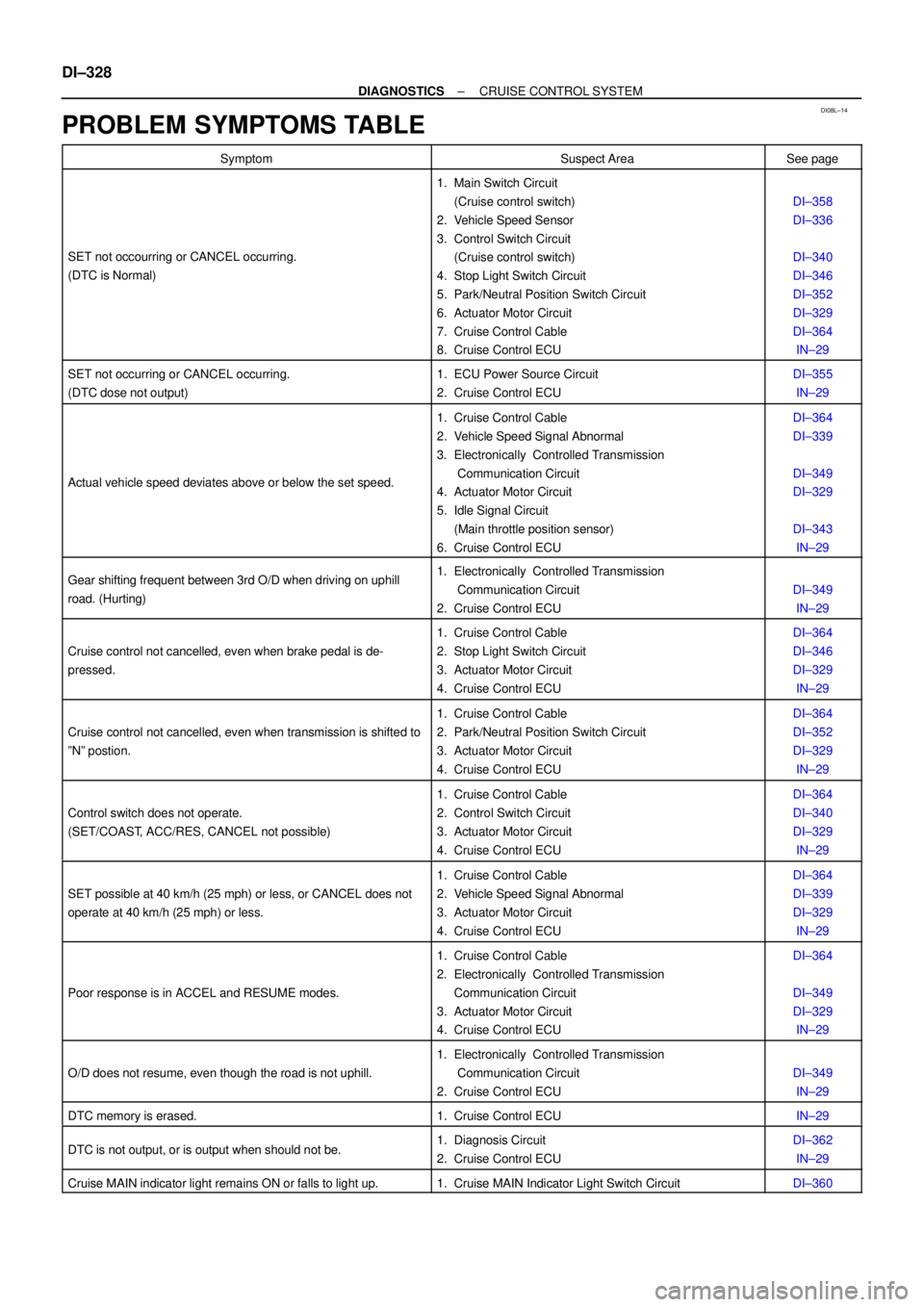
PROBLEM SYMPTOMS TABLE
SymptomSuspect AreaSee page
SET not occourring or CANCEL occurring.
(DTC is Normal)
1. Main Switch Circuit
(Cruise control switch)
2. Vehicle Speed Sensor
3. Control Switch Circuit
(Cruise control switch)
4. Stop Light Switch Circuit
5. Park/Neutral Position Switch Circuit
6. Actuator Motor Circuit
7. Cruise Control Cable
8. Cruise Control ECU
DI±358
DI±336
DI±340
DI±346
DI±352
DI±329
DI±364
IN±29
SET not occurring or CANCEL occurring.
(DTC dose not output)1. ECU Power Source Circuit
2. Cruise Control ECUDI±355
IN±29
Actual vehicle speed deviates above or below the set speed.
1. Cruise Control Cable
2. Vehicle Speed Signal Abnormal
3. Electronically Controlled Transmission
Communication Circuit
4. Actuator Motor Circuit
5. Idle Signal Circuit
(Main throttle position sensor)
6. Cruise Control ECUDI±364
DI±339
DI±349
DI±329
DI±343
IN±29
Gear shifting frequent between 3rd O/D when driving on uphill
road. (Hurting)1. Electronically Controlled Transmission
Communication Circuit
2. Cruise Control ECU
DI±349
IN±29
Cruise control not cancelled, even when brake pedal is de-
pressed.
1. Cruise Control Cable
2. Stop Light Switch Circuit
3. Actuator Motor Circuit
4. Cruise Control ECUDI±364
DI±346
DI±329
IN±29
Cruise control not cancelled, even when transmission is shifted to
ºNº postion.
1. Cruise Control Cable
2. Park/Neutral Position Switch Circuit
3. Actuator Motor Circuit
4. Cruise Control ECUDI±364
DI±352
DI±329
IN±29
Control switch does not operate.
(SET/COAST, ACC/RES, CANCEL not possible)
1. Cruise Control Cable
2. Control Switch Circuit
3. Actuator Motor Circuit
4. Cruise Control ECUDI±364
DI±340
DI±329
IN±29
SET possible at 40 km/h (25 mph) or less, or CANCEL does not
operate at 40 km/h (25 mph) or less.
1. Cruise Control Cable
2. Vehicle Speed Signal Abnormal
3. Actuator Motor Circuit
4. Cruise Control ECUDI±364
DI±339
DI±329
IN±29
Poor response is in ACCEL and RESUME modes.
1. Cruise Control Cable
2. Electronically Controlled Transmission
Communication Circuit
3. Actuator Motor Circuit
4. Cruise Control ECUDI±364
DI±349
DI±329
IN±29
O/D does not resume, even though the road is not uphill.
1. Electronically Controlled Transmission
Communication Circuit
2. Cruise Control ECU
DI±349
IN±29
DTC memory is erased.1. Cruise Control ECUIN±29
DTC is not output, or is output when should not be.1. Diagnosis Circuit
2. Cruise Control ECUDI±362
IN±29
Cruise MAIN indicator light remains ON or falls to light up.1. Cruise MAIN Indicator Light Switch CircuitDI±360