Page 1162 of 4592
RADIATOR
1596 Author�: Date�:
(b) Check the lock plate height (H) after completing the caulk-
ing.
Plate height: 7.40 ± 7.8")
S04700
H
S04704
SST
S01713
Tank
Lock
O±RingPlate CO±22
± COOLING (5S±FE)RADIATOR
1596 Author�: Date�:
(b) Check the lock plate height (H) after completing the caulk-
ing.
Plate height: 7.40 ± 7.80 mm (0.2913 ± 0.3071 in.)
If not within the specified height, adjust the stopper bolt of the
handle again and caulk again.
6. INSTALL ECT SWITCH
(a) Install a new O±ring to the ECT switch.
(b) Install the ECT switch.
7. INSTALL DRAIN PLUG
(a) Install a new O±ring to the drain plug.
(b) Install the drain plug.
8. INSPECT FOR WATER LEAKS
(a) Plug the inlet and outlet pipes of the radiator with SST.
SST 09230±01010
(b) Using a radiator cap tester, apply pressure to the radiator.
Test pressure: 177 kPa (1.8 kgf/cm
2, 26 psi)
(c) Submerge the radiator in water.
(d) Inspect for leaks.
HINT:
On radiators with resin tanks, there is a clearance between the
tank and lock plate where a minute amount of air will remain,
giving the appearance of an air leak when the radiator is sub-
merged in water. Therefore, before doing the water leak test,
first swish the radiator around in the water until all air bubbles
disappear.
Page 1167 of 4592
CO06P±03
S05956
S05957
± COOLING (5S±FE)ELECTRIC COOLING FAN
CO±27
1601 Author�: Date�:
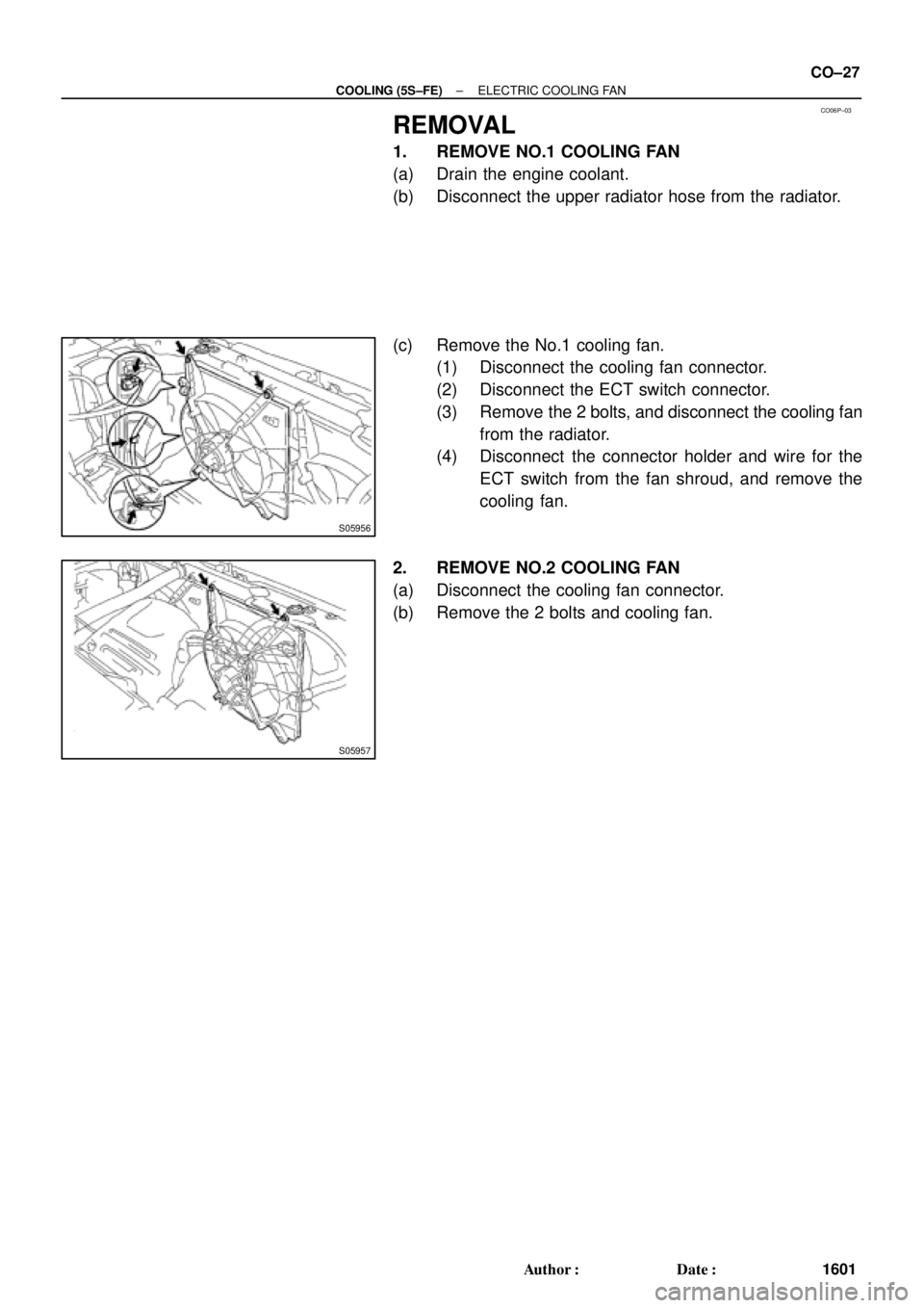
REMOVAL
1. REMOVE NO.1 COOLING FAN
(a) Drain the engine coolant.
(b) Disconnect the upper radiator hose from the radiator.
(c) Remove the No.1 cooling fan.
(1) Disconnect the cooling fan connector.
(2) Disconnect the ECT switch connector.
(3) Remove the 2 bolts, and disconnect the cooling fan
from the radiator.
(4) Disconnect the connector holder and wire for the
ECT switch from the fan shroud, and remove the
cooling fan.
2. REMOVE NO.2 COOLING FAN
(a) Disconnect the cooling fan connector.
(b) Remove the 2 bolts and cooling fan.
Page 1180 of 4592
CO03E±03
P12942
CO±6
± COOLING (1MZ±FE)WATER PUMP
1614 Author�: Date�:
REMOVAL
1. DRAIN ENGINE COOLANT
2. REMOVE TIMING BELT (See page EM±15)
3. REMOVE CAMSHAFT TIMING PULLEYS
(See page EM±15)
4. REMOVE NO.2 IDLER PULLEY
(See page EM±15)
5. REMOVE NO.3 TIMING BELT COVER
(See page EM±32)
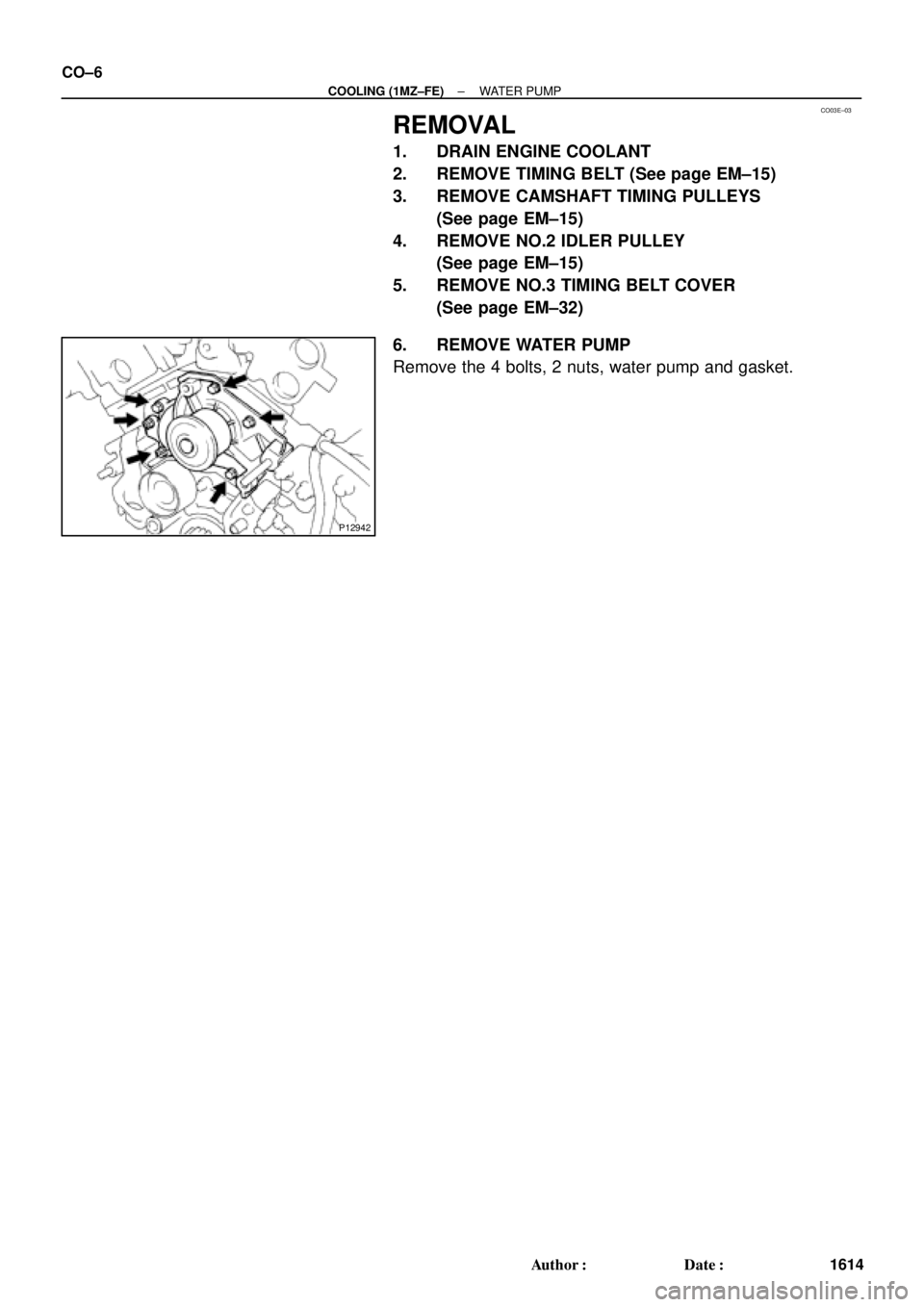
6. REMOVE WATER PUMP
Remove the 4 bolts, 2 nuts, water pump and gasket.
Page 1184 of 4592
CO03I±03
S04581
S04502
S04503
CO±10
± COOLING (1MZ±FE)THERMOSTAT
1618 Author�: Date�:
REMOVAL
HINT:
Removal of the thermostat would have an adverse effect, caus-
ing a lowering of cooling efficiency. Do not remove the thermo-
stat, even if the engine tends to overheat.
1. DRAIN ENGINE COOLANT
2. REMOVE AIR CLEANER CAP ASSEMBLY AND AIR
FILTER
3. DISCONNECT NO.2 ECT SWITCH CONNECTOR
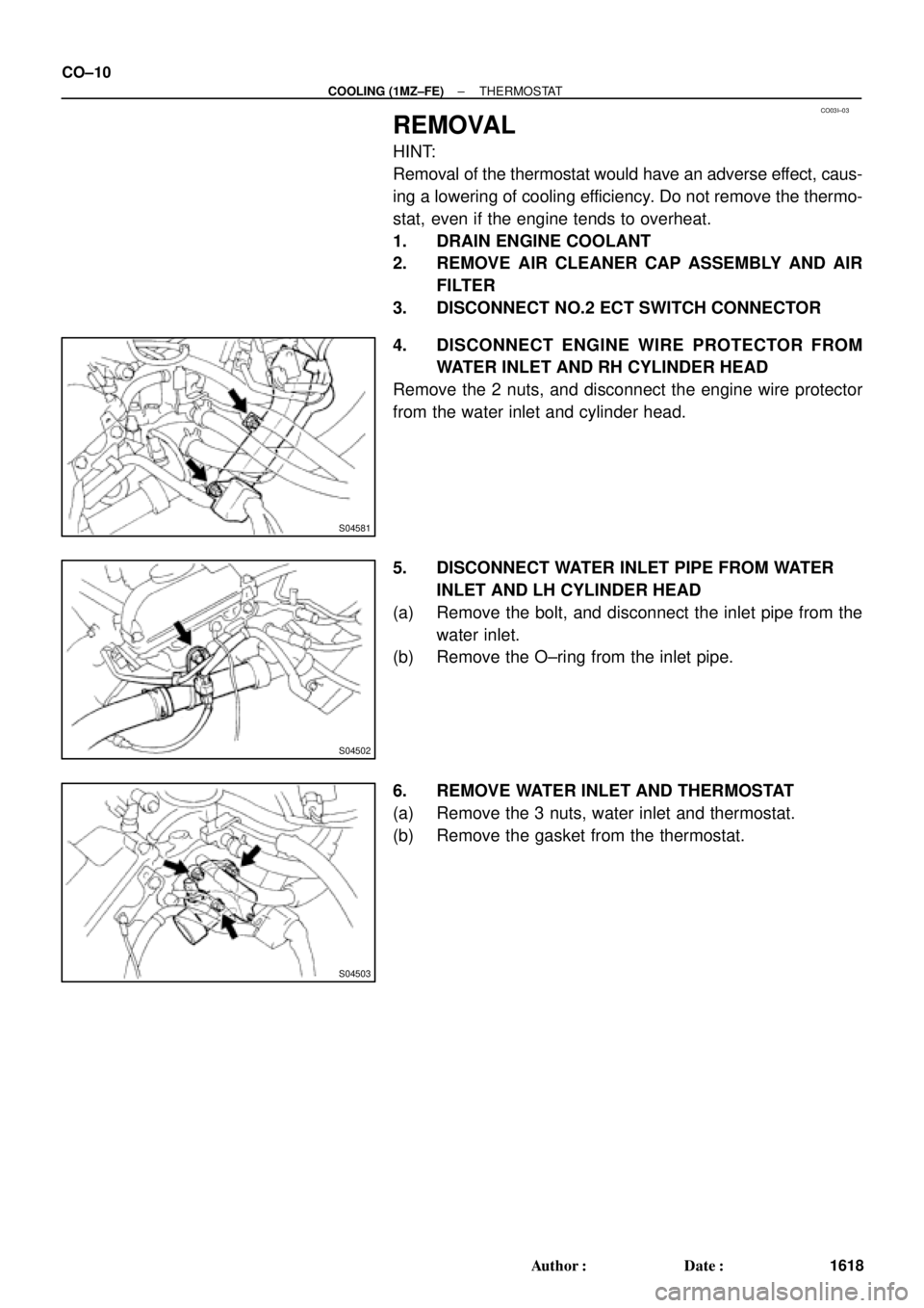
4. DISCONNECT ENGINE WIRE PROTECTOR FROM
WATER INLET AND RH CYLINDER HEAD
Remove the 2 nuts, and disconnect the engine wire protector
from the water inlet and cylinder head.
5. DISCONNECT WATER INLET PIPE FROM WATER
INLET AND LH CYLINDER HEAD
(a) Remove the bolt, and disconnect the inlet pipe from the
water inlet.
(b) Remove the O±ring from the inlet pipe.
6. REMOVE WATER INLET AND THERMOSTAT
(a) Remove the 3 nuts, water inlet and thermostat.
(b) Remove the gasket from the thermostat.
Page 1192 of 4592
RADIATOR
1626 Author�: Date�:
REMOVAL
HINT:
�At the time of installation, please refer to the following
items.
�Start the")
CO03O±03
S04725
B05937
Lower
Hose
Oil
Cooler
Hose
CO±18
± COOLING (1MZ±FE)RADIATOR
1626 Author�: Date�:
REMOVAL
HINT:
�At the time of installation, please refer to the following
items.
�Start the engine, and check for coolant and A/T fluid
leaks.
�Check the A/T fluid level. (See page DI±438)
1. DRAIN ENGINE COOLANT
2. CANADA:
DISCONNECT RELAY BLOCK (FOR DAYTIME
RUNNING LIGHT SYSTEM) FROM BATTERY
HOLD±DOWN CLAMP
3. DISCONNECT UPPER RADIATOR HOSE FROM
RADIATOR
4. DISCONNECT LOWER RADIATOR HOSE FROM
WATER INLET PIPE
5. DISCONNECT A/T OIL COOLER HOSES FROM OIL
COOLER PIPES
6. DISCONNECT NO.1 AND NO.2 COOLING FAN
CONNECTORS
7. DISCONNECT NO.1 ECT SWITCH WIRE CONNECTOR
8. REMOVE RADIATOR AND COOLING FANS
ASSEMBLY
(a) Remove the 2 bolts and 2 upper supports.
Torque: 12.8 N´m (130 kgf´cm, 9 ft´lbf)
(b) Lift out the radiator, and remove the radiator and cooling
fans assembly.
(c) Remove the 2 lower supports.
9. REMOVE A/T OIL COOLER HOSES FROM
RADIATOR
10. REMOVE LOWER RADIATOR HOSE FROM
RADIATOR
Page 1203 of 4592
CO03U±03
B05943
B05944
± COOLING (1MZ±FE)ELECTRIC COOLING FAN
CO±29
1637 Author�: Date�:
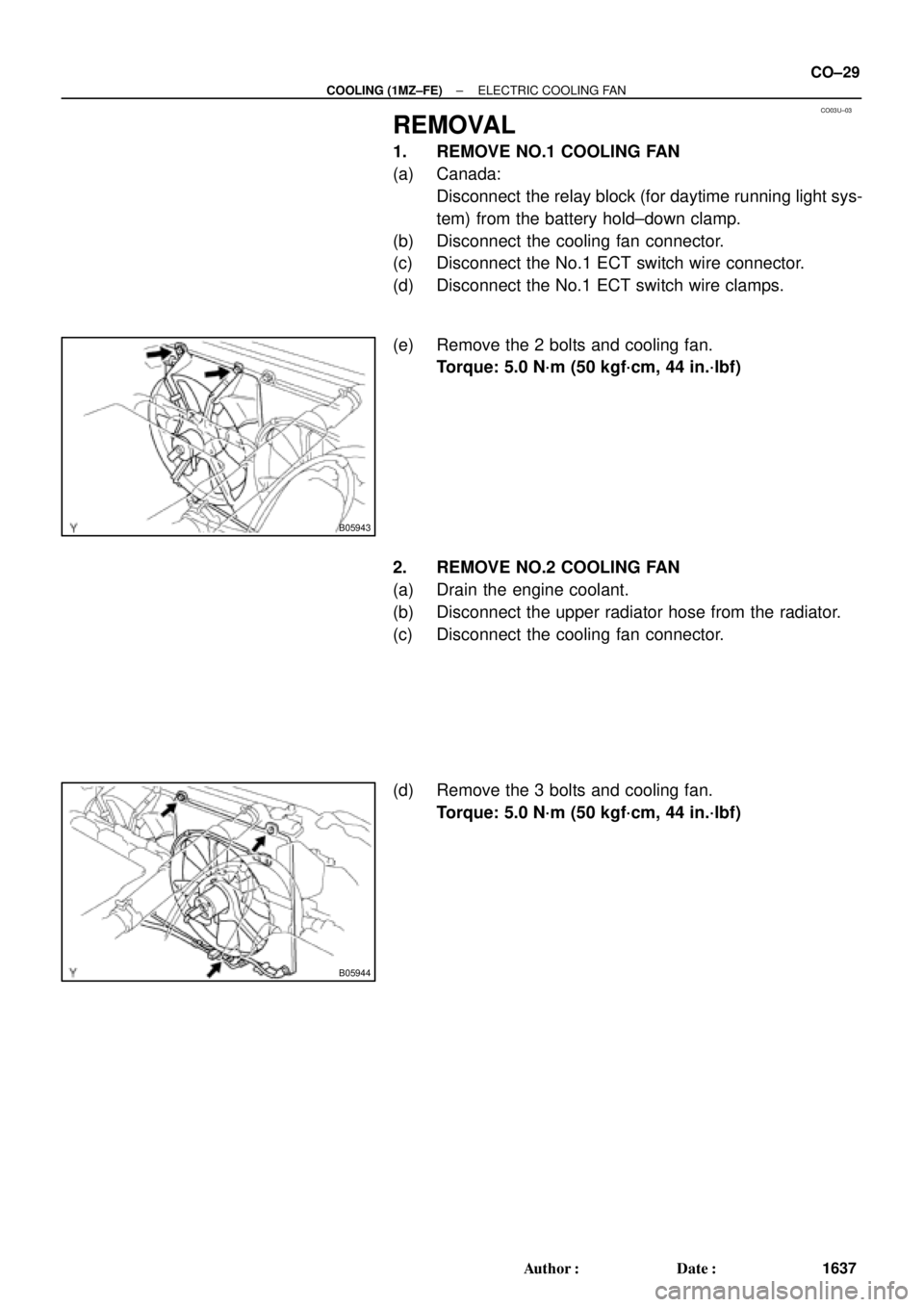
REMOVAL
1. REMOVE NO.1 COOLING FAN
(a) Canada:
Disconnect the relay block (for daytime running light sys-
tem) from the battery hold±down clamp.
(b) Disconnect the cooling fan connector.
(c) Disconnect the No.1 ECT switch wire connector.
(d) Disconnect the No.1 ECT switch wire clamps.
(e) Remove the 2 bolts and cooling fan.
Torque: 5.0 N´m (50 kgf´cm, 44 in.´lbf)
2. REMOVE NO.2 COOLING FAN
(a) Drain the engine coolant.
(b) Disconnect the upper radiator hose from the radiator.
(c) Disconnect the cooling fan connector.
(d) Remove the 3 bolts and cooling fan.
Torque: 5.0 N´m (50 kgf´cm, 44 in.´lbf)
Page 2521 of 4592
EC03D±05
B06534
Vapor Pressure Sensor
ConnectorVSV for Vapor Pressure Sensor
ConnectorEVAP Line Hose
Vent Line Hose
Air Inlet Line Hose
Purge Line Hose
Air Drain Hose
39.2 (400, 29)
N´m (kgf´cm, ft´lbf) : Specified torqueCharcoal Canister
Assembly
Charcoal Canister
Vapor Pressure Sensor
Mounting Bolt
± EMISSION CONTROL (5S±FE)EVAPORATIVE EMISSION (EVAP) CONTROL SYSTEM
EC±5
1403 Author�: Date�:
EVAPORATIVE EMISSION (EVAP) CONTROL SYSTEM
COMPONENTS
Page 2525 of 4592
EVAPORATIVE EMISSION (EVAP) CONTROL")
B01252
AirDisconnect
Air Inlet Line Hose
B01253
Pinch
Push
AA
Pinch
B01148
B01149
Air
Purge Port
Vent Port
Air Drain Port
Cap
EVAP
Port
± EMISSION CONTROL (5S±FE)EVAPORATIVE EMISSION (EVAP) CONTROL SYSTEM
EC±9
1407 Author�: Date�:
HINT:
In the condition that the fuel fuel is full, as the float value of the
fill check valve is closed and has no ventilation, it is necessary
to check the fuel amount (volume).
(d) Check if there is any struck in the vent line hose and EVAP
line hose.
If there is no stuck in hoses, replace the fuel cutoff valve and fill
check valve.
(e) Reconnect the purge line hose and EVAP line hose to the
charcoal canister.
7. CHECK AIR INLET LINE
(a) Disconnect the air inlet line hose from the charcoal canis-
ter.
(b) Check that there is ventilation in the air inlet line.
(c) Reconnect the air inlet line hose to the charcoal canister.
8. REMOVE CHARCOAL CANISTER ASSEMBLY
(a) Disconnect the VSV connector.
(b) Disconnect the vapor pressure sensor connector.
(c) Disconnect the purge line hose, EVAP line hose and air
inlet line hose from the charcoal canister.
(d) Disconnect the vent line hose from the charcoal canister.
(1) Push the connector deep inside.
(2) Pinch portion A.
(3) Pull out the connector.
(e) Remove the 2 charcoal canister mounting bolts.
(f) Remove the vapor pressure sensor mounting bolt.
(g) Remove the charcoal canister assembly.
9. INSPECT CHARCOAL CANISTER
(a) Visually check the charcoal canister for cracks or dam-
age.
(b) Inspect the charcoal canister operation.
(1) Plug the vent port with a cap.
(2) While holding the purge port closed, blow air (1.76
kPa, 18 gf/cm
2, 0.26 psi) into the EVAP port and
check that air flows from the air drain port.

N´m (kgf´cm, ft")