Page 1047 of 4592
 Using SST, remove the shoe hold±down spring, 2 cups
and pin.
SST 09718±00010
(b) Using a scre")
R00248
SST
Z03633
BR1540
SST
± BRAKEREAR DRUM BRAKE
BR±33
2056 Author�: Date�:
5. REMOVE REAR SHOE
(a) Using SST, remove the shoe hold±down spring, 2 cups
and pin.
SST 09718±00010
(b) Using a screwdriver, disconnect the parking brake cable
from the anchor plate.
(c) Using pliers, disconnect the parking brake cable from the
lever and remove the rear shoe together with adjuster.
NOTICE:
Do not allow oil or grease on the rubbing face.
6. REMOVE ADJUSTER FROM REAR SHOE
(a) Remove the adjusting lever spring.
(b) Remove the adjuster together with the return spring.
7. REMOVE AUTOMATIC ADJUSTING LEVER AND
PARKING BRAKE LEVER
(a) Remove the E±ring.
(b) Remove the automatic adjusting lever.
(c) Remove the C±washer.
(d) Remove the parking brake lever.
8. REMOVE WHEEL CYLINDER
(a) Using SST, disconnect the brake line. Use a container to
catch the brake fluid.
Torque: 15 N´m (155 kgf´cm, 11 ft´lbf)
SST 09751±36011
(b) Remove the 2 bolts and the wheel cylinder.
Torque: 10 N´m (100 kgf´cm, 7 ft´lbf)
9. DISASSEMBLE WHEEL CYLINDER
(a) Remove the 2 boots.
(b) Remove the 2 pistons and springs.
(c) Remove the 2 piston cups.
Page 1048 of 4592

BR0AY±03
BR1542
F06408
BR1543
BR±34
± BRAKEREAR DRUM BRAKE
2057 Author�: Date�:
INSPECTION
1. INSPECT DISASSEMBLED PARTS
Inspect the disassembled parts for wear, rust or damage.
2. MEASURE BRAKE SHOE LINING THICKNESS
Using a ruler, measure the shoe lining thickness.
Standard thickness: 5.0 mm (0.197 in.)
Minimum thickness: 1.0 mm (0.039 in.)
If the thickness is less than the minimum, or shows signs of un-
even wear, replace the brake shoes.
HINT:
If any of the brake shoes have to be replaced, replace all of the
rear brake shoes in order to maintain even braking.
3. MEASURE BRAKE DRUM INSIDE DIAMETER
Using brake drum gauge or equivalent, measure the inside di-
ameter of the drum.
Standard inside diameter: 228.6 mm (9.000 in.)
Maximum inside diameter: 230.6 mm (9.079 in.)
If the drum is scored or worn, the brake drum may be lathed to
the maximum inside diameter.
4. INSPECT REAR BRAKE LINING AND DRUM FOR
PROPER CONTACT
If the contact between the brake lining and drum is improper, re-
pair the lining with a brake shoe grinder, or replace the brake
shoe assembly.
Page 1049 of 4592
.
NOTICE:
Apply lithium soap base glyco")
BR0AZ±02
W01679
BR1553
F06423
± BRAKEREAR DRUM BRAKE
BR±35
2058 Author�: Date�:
INSTALLATION
Installation is in the reverse order of removal
(See page BR±32).
NOTICE:
Apply lithium soap base glycol grease and high tempera-
ture grease to the parts indicated by the arrows
(See page BR±31).
1. AFTER INSTALLATION, FILL BRAKE RESERVOIR
WITH BRAKE FLUID, BLEED BRAKE SYSTEM
(See page BR±4)
2. CHECK FOR LEAKS
3. CHECK OPERATION OF AUTOMATIC ADJUSTING
MECHANISM
(a) Move the parking brake lever of the rear shoe back and
forth. Check that the adjuster turns.
If the adjuster does not turn, check for incorrect installation of
the rear brake.
(b) Adjust the adjuster length as short as possible.
(c) Align the adjusting hole on the brake drum and the largest
hole on the axle carrier, install the brake drum.
(d) Pull the parking brake lever all the way up until a clicking
sound can no longer be heard.
4. CHECK CLEARANCE BETWEEN BRAKE SHOES AND
DRUM
(a) Remove the drum.
(b) Measure the brake drum inside diameter and diameter
between the brake shoes. Check that the difference be-
tween the diameters is the correct shoe clearance.
Shoe clearance: 0.6 mm (0.024 in.)
If incorrect, check the parking brake system.
Page 1050 of 4592
BR0B0±03
F02610
Pad Support Plate
Outer Pad
Anti±squeal Shim
Inner Anti±squeal Shim Anti±squeal Shim
Inner Anti±squeal Shim
Inner Pad
Pad Support Plate
Disc brake grease
N´m (kgf´cm, ft´lbf) : Specified torque
29 (300, 21)20 (200, 14)
BR±36
± BRAKEREAR BRAKE PAD
2059 Author�: Date�:
REAR BRAKE PAD
COMPONENTS
Page 1051 of 4592

BR0B1±03
R00591
R00514
R10387
± BRAKEREAR BRAKE PAD
BR±37
2060 Author�: Date�:
REPLACEMENT
1. REMOVE REAR WHEEL
Remove the wheel and temporarily fasten the disc with the hub
nuts.
2. INSPECT PAD LINING THICKNESS
Check the pad thickness through the caliper inspection hole
and replace pads if not within specification.
Minimum thickness: 1.0 mm (0.039 in.)
3. LIFT UP CALIPER
(a) Remove the bolt and flexible hose from the bracket.
(b) Remove the installation bolt from the torque plate.
(c) Lift up the caliper and suspend it securely.
HINT:
Do not disconnect the flexible hose.
4. REMOVE 2 BRAKE PADS
5. REMOVE 4 ANTI±SQUEAL SHIMS
6. REMOVE 4 PAD SUPPORT PLATES
NOTICE:
The support plates can be used again provided that they
have sufficient rebound, no deformation, cracks or wear,
and have had all rust, dirt and foreign particles cleaned off.
7. CHECK DISC THICKNESS AND RUNOUT
(See page BR±42)
8. INSTALL 4 PAD SUPPORT PLATES
9. INSTALL NEW PADS
NOTICE:
When replacing worn pads, the anti±squeal shims must be
replaced together with the pads.
(a) Apply disc brake grease to both side of the inner anti±
squeal shims (See page BR±36).
(b) Install the 2 anti±squeal shims on each pad.
(c) Install 2 pads with the pad wear indicator plate facing up-
ward.
NOTICE:
There should be no oil or grease adhering to the friction
surfaces of the pads or the disc.
10. INSTALL CALIPER
(a) Draw out a small amount of brake fluid from the reservoir.
(b) Press in the piston with a hammer handle or similar imple-
ment.
HINT:
If the piston is difficult to push in, loosen the bleeder plug and
push in the piston while letting some brake fluid escape.
(c) Install the caliper and torque the installation bolt.
Torque: 20 N´m (200 kgf´cm, 14 ft´lbf)
(d) Install the flexible hose and bolt to the bracket.
Torque: 29 N´m (300 kgf´cm, 21 ft´lbf)
Page 1052 of 4592
BR±38
± BRAKEREAR BRAKE PAD
2061 Author�: Date�:
11. INSTALL REAR WHEEL
Torque: 103 N´m (1.050 kgf´cm, 76 ft´lbf)
12. DEPRESS BRAKE PEDAL SEVERAL TIMES
13. CHECK THAT FLUID LEVEL IS AT MAX LINE
Page 1053 of 4592
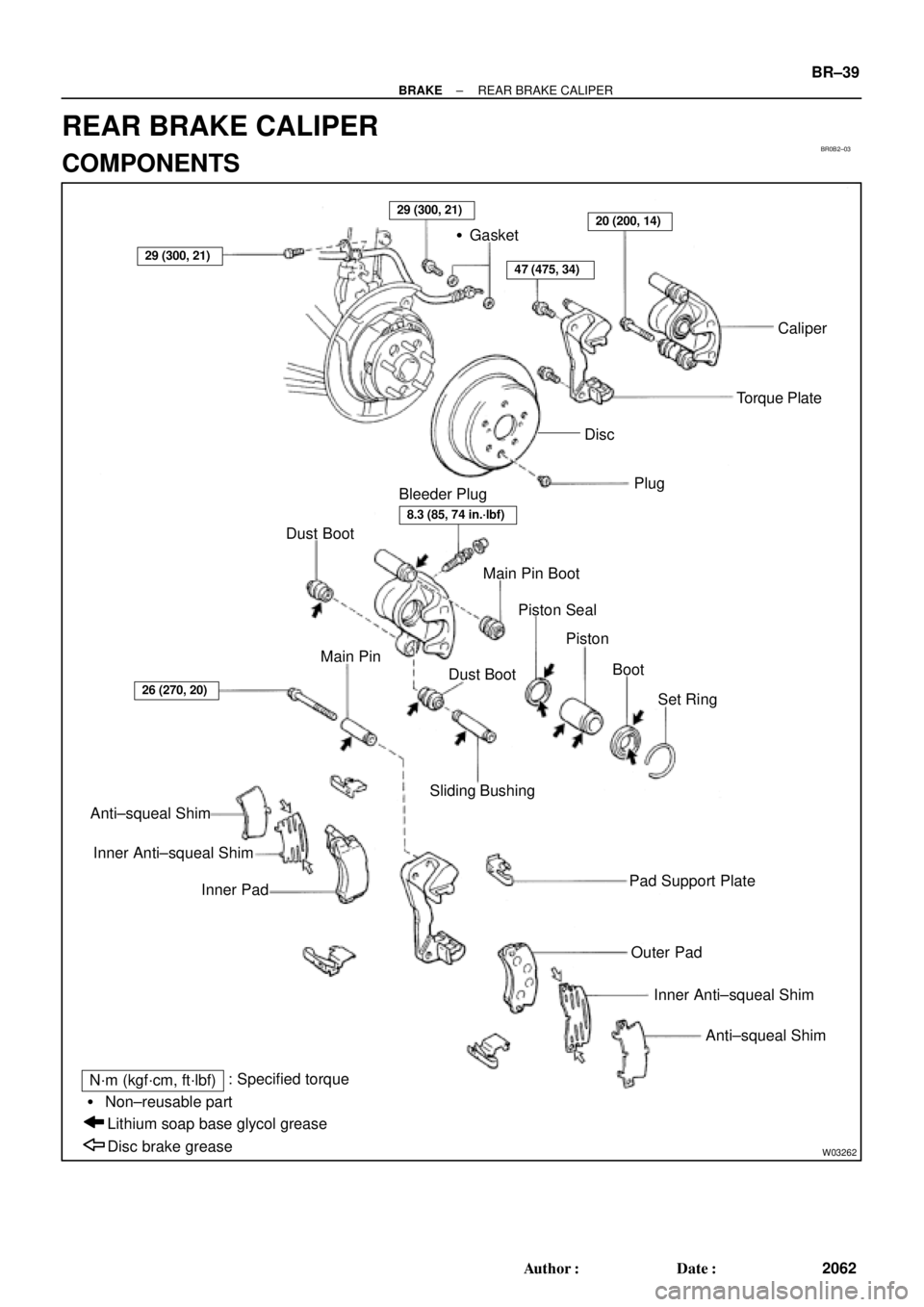
BR0B2±03
W03262
�Gasket
Caliper
Torque Plate
Plug
Bleeder Plug
Dust Boot
Main Pin Boot
Piston Seal
Piston
Boot
Set Ring Dust Boot Main Pin
Anti±squeal Shim
Inner Anti±squeal Shim
Inner PadSliding Bushing
Pad Support Plate
Outer Pad
Inner Anti±squeal Shim
Anti±squeal Shim
Disc brake grease Lithium soap base glycol grease � Non±reusable part
N´m (kgf´cm, ft´lbf): Specified torque
47 (475, 34)
20 (200, 14)
26 (270, 20)
29 (300, 21)
29 (300, 21)
8.3 (85, 74 in.´lbf)
Disc
± BRAKEREAR BRAKE CALIPER
BR±39
2062 Author�: Date�:
REAR BRAKE CALIPER
COMPONENTS
Page 1054 of 4592

2. DISCONNECT FLEXIBLE HOSE
(a) Remove the unio")
BR0B3±03
W03263
W03264
BR±40
± BRAKEREAR BRAKE CALIPER
2063 Author�: Date�:
REMOVAL
1. REMOVE REAR WHEEL
Torque: 103 N´m (1.050 kgf´cm, 76 ft´lbf)
2. DISCONNECT FLEXIBLE HOSE
(a) Remove the union bolt and 2 gaskets from the caliper,
then disconnect the flexible hose from the caliper.
Torque: 29 N´m (300 kgf´cm, 21 ft´lbf)
HINT:
At the time of installation, please refer to the following item.
Insert the flexible hose lock securely in the lock hole in the cali-
per.
(b) Use a container to catch the brake fluid as it drains out.
3. REMOVE CALIPER
(a) Remove the installation bolt.
Torque: 20 N´m (200 kgf´cm, 14 ft´lbf)
(b) Remove the caliper from the torque plate.
4. REMOVE 2 BRAKE PADS WITH 4 ANTI±SQUEAL
SHIMS
5. REMOVE 4 PAD SUPPORT PLATES
NOTICE:
At the time of installation, please refer to the following item.
There should be no oil or grease adhering to the friction
surfaces of the pads or disc.
6. REMOVE MAIN PIN
Loosen the main pin installation bolt and remove the main pin.
Torque: 26 N´m (270 kgf´cm, 20 ft´lbf)
 :")