Page 602 of 4592

± BODY ELECTRICALIGNITION SWITCH AND KEY UNLOCK WARNING
SWITCHBE±21
2241 Author�: Date�:
Tester connectionConditionSpecified condition
A1 ± GroundDoor lock manual switch OFF or UNLOCKNo continuity
A1 ± GroundDoor lock manual switch LOCKContinuity
A2 ± GroundDoor lock manual switch OFF or LOCKNo continuity
A2 ± GroundDoor lock manual switch UNLOCKContinuity
A3 ± GroundDriver's and passenger's door key lock and
unlock switch OFF or UNLOCKNo continuity
A3 ± GroundDriver's or passenger's door key lock and unlock
switch LOCKContinuity
A4 ± GroundDriver's door key lock and unlock switch OFF or
LOCKNo continuity
A4 ± GroundDriver's door key lock and unlock switch
UNLOCKContinuity
A5 ± GroundPassenger's door key lock and unlock switch
OFF or LOCKNo continuity
A5 ± GroundPassenger's door key lock and unlock switch
UNLOCKContinuity
A6 ± A7ConstantContinuity
A8 ± GroundPassenger's door courtesy switch OFF (Door
closed)No continuity
A8 ± GroundPassenger's door courtesy switch ON (Door
opened)Continuity
A9 ± GroundDriver's door unlock detection switch OFF (Door
closed)No continuity
A9 ± GroundDriver's door unlock detection switch ON (Door
opened)Continuity
A10 ± GroundPassenger's door unlock detection switch OFF
(Door closed)No continuity
A10 ± GroundPassenger's door unlock detection switch ON
(Door opened)Continuity
A11 ± GroundRear door unlock detection switch OFF (Door
closed)No continuity
A11 ± GroundRear door unlock detection switch ON (Door
opened)Continuity
A12 ± GroundConstantContinuity
A13 ± GroundConstantBattery positive voltage
B1 ± GroundLight control switch OFFNo voltage
B1 ± GroundLight control switch TAIL or HEADBattery positive voltage
B4 ± GroundLight control switch OFF or TAILNo voltage
B4 ± GroundLight control switch HEADBattery positive voltage
B2 ± Ground
B3 ± GroundConstantBattery positive voltage
If the circuit is as specified, try replacing the relay with a new
one.
If the circuit is not as specified, inspect the circuits connected
to other parts.
Page 633 of 4592

N20217
OFF
ONOhmmeter
Z05732
Warning Light
Ignition
Switch
Battery
1
BE0044
Warning Light
Ignition
Switch
Battery
Z16167
1
2 OFF
ON
N02354
1
2OFF
ON BE±52
± BODY ELECTRICALCOMBINATION METER
2272 Author�: Date�:
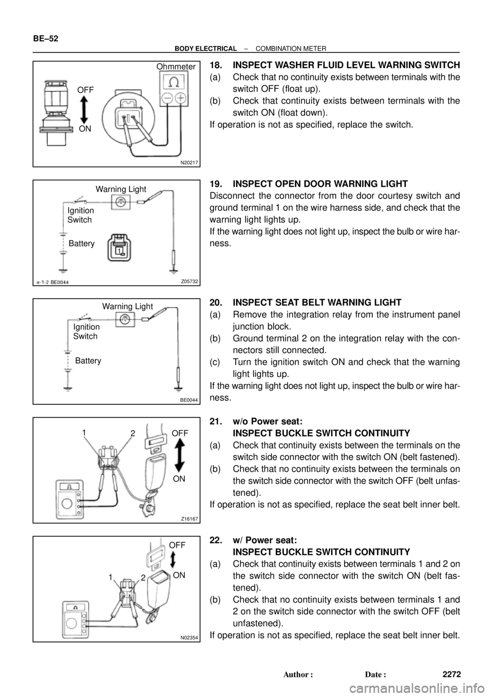
18. INSPECT WASHER FLUID LEVEL WARNING SWITCH
(a) Check that no continuity exists between terminals with the
switch OFF (float up).
(b) Check that continuity exists between terminals with the
switch ON (float down).
If operation is not as specified, replace the switch.
19. INSPECT OPEN DOOR WARNING LIGHT
Disconnect the connector from the door courtesy switch and
ground terminal 1 on the wire harness side, and check that the
warning light lights up.
If the warning light does not light up, inspect the bulb or wire har-
ness.
20. INSPECT SEAT BELT WARNING LIGHT
(a) Remove the integration relay from the instrument panel
junction block.
(b) Ground terminal 2 on the integration relay with the con-
nectors still connected.
(c) Turn the ignition switch ON and check that the warning
light lights up.
If the warning light does not light up, inspect the bulb or wire har-
ness.
21. w/o Power seat:
INSPECT BUCKLE SWITCH CONTINUITY
(a) Check that continuity exists between the terminals on the
switch side connector with the switch ON (belt fastened).
(b) Check that no continuity exists between the terminals on
the switch side connector with the switch OFF (belt unfas-
tened).
If operation is not as specified, replace the seat belt inner belt.
22. w/ Power seat:
INSPECT BUCKLE SWITCH CONTINUITY
(a) Check that continuity exists between terminals 1 and 2 on
the switch side connector with the switch ON (belt fas-
tened).
(b) Check that no continuity exists between terminals 1 and
2 on the switch side connector with the switch OFF (belt
unfastened).
If operation is not as specified, replace the seat belt inner belt.
Page 644 of 4592

Z05742
123 456
7 8 9 10 11 121314 Wire harness side:
e±14±1±A
N20560
1 2 3 4 5
N20561
1 2 3 4 5
N14863
1235 12
35
± BODY ELECTRICALPOWER WINDOW CONTROL SYSTEM
BE±63
2283 Author�: Date�:
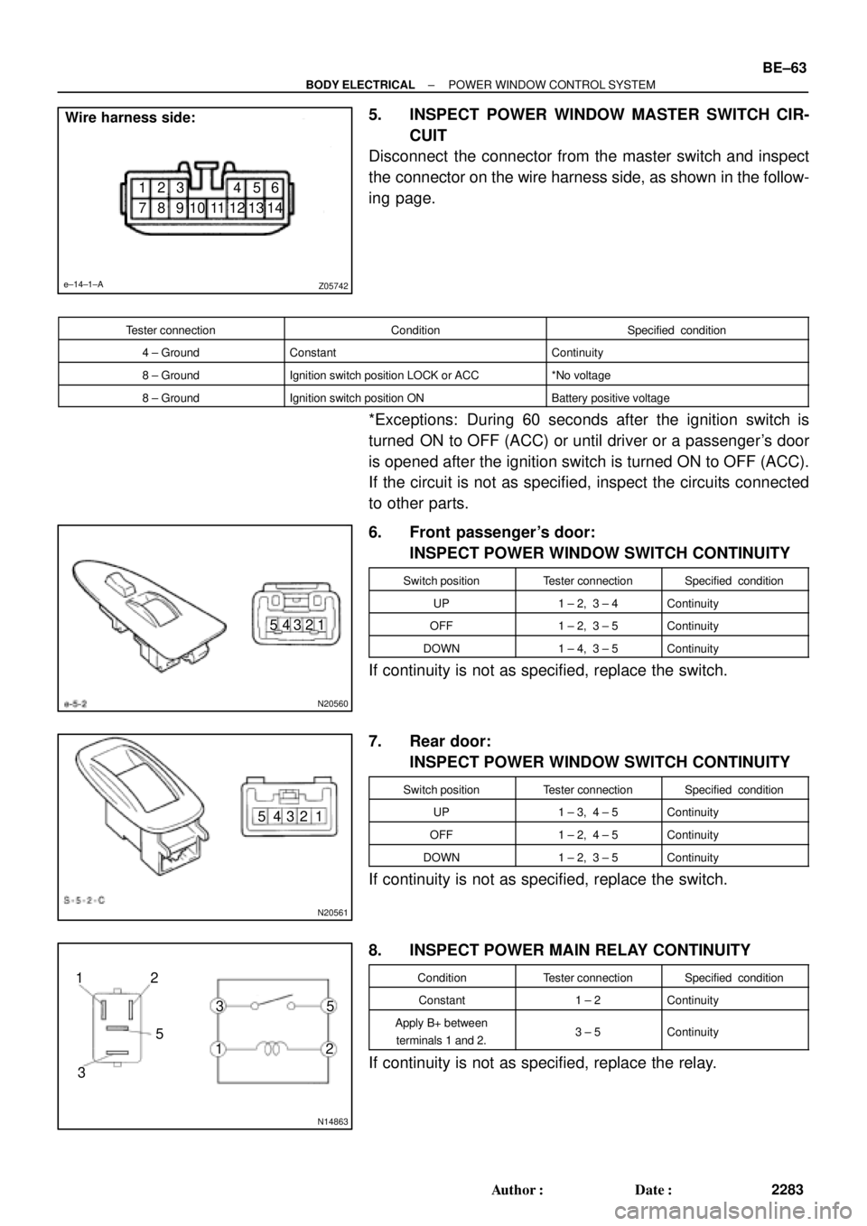
5. INSPECT POWER WINDOW MASTER SWITCH CIR-
CUIT
Disconnect the connector from the master switch and inspect
the connector on the wire harness side, as shown in the follow-
ing page.
Tester connectionConditionSpecified condition
4 ± GroundConstantContinuity
8 ± GroundIgnition switch position LOCK or ACC*No voltage
8 ± GroundIgnition switch position ONBattery positive voltage
*Exceptions: During 60 seconds after the ignition switch is
turned ON to OFF (ACC) or until driver or a passenger's door
is opened after the ignition switch is turned ON to OFF (ACC).
If the circuit is not as specified, inspect the circuits connected
to other parts.
6. Front passenger's door:
INSPECT POWER WINDOW SWITCH CONTINUITY
Switch positionTester connectionSpecified condition
UP1 ± 2, 3 ± 4Continuity
OFF1 ± 2, 3 ± 5Continuity
DOWN1 ± 4, 3 ± 5Continuity
If continuity is not as specified, replace the switch.
7. Rear door:
INSPECT POWER WINDOW SWITCH CONTINUITY
Switch positionTester connectionSpecified condition
UP1 ± 3, 4 ± 5Continuity
OFF1 ± 2, 4 ± 5Continuity
DOWN1 ± 2, 3 ± 5Continuity
If continuity is not as specified, replace the switch.
8. INSPECT POWER MAIN RELAY CONTINUITY
ConditionTester connectionSpecified condition
Constant1 ± 2Continuity
Apply B+ between
terminals 1 and 2.3 ± 5Continuity
If continuity is not as specified, replace the relay.
Page 645 of 4592
N20555
TMMK made:
TMC made:1
2
N20556
TMMK made:
TMC made:1
2 BE±64
± BODY ELECTRICALPOWER WINDOW CONTROL SYSTEM
2284 Author�: MH Date�: 3/7/02
9. Left side door:
INSPECT MOTOR OPERATION
(a) Connect the positive (+) lead from the battery to terminal
1 and the negative (±) lead to terminal 2, and check that
the motor turns clockwise.
(b) Reverse the polarity, and check that the motor turns coun-
terclockwise.
If operation is not as specified, replace the motor.
Page 646 of 4592
N20557
TMMK made:
TMC made:1
2
N20558
TMMK made:
TMC made:1 2
± BODY ELECTRICALPOWER WINDOW CONTROL SYSTEM
BE±65
2285 Author�: Date�:
10. Right side door:
INSPECT MOTOR OPERATION
(a) Connect the positive (+) lead from the battery to terminal
1 and the negative (±) lead to terminal 2, and check that
the motor turns clockwise.
(b) Reverse the polarity, and check that the motor turns coun-
terclockwise.
If operation is not as specified, replace the motor.
Page 648 of 4592

I21313
2
1
I12561
2
1
I12560
21
N20564
(b) Close(c) Open
A3 Type B:
± BODY ELECTRICALPOWER WINDOW CONTROL SYSTEM
BE±67
2287 Author�: Date�:
(f) Approximately 60 seconds later, connect the positive (+)
lead from the battery to terminal 1 and the negative (±)
lead to terminal 2, and check that the window begins to
descend.
If operation is not as specified, replace the motor.
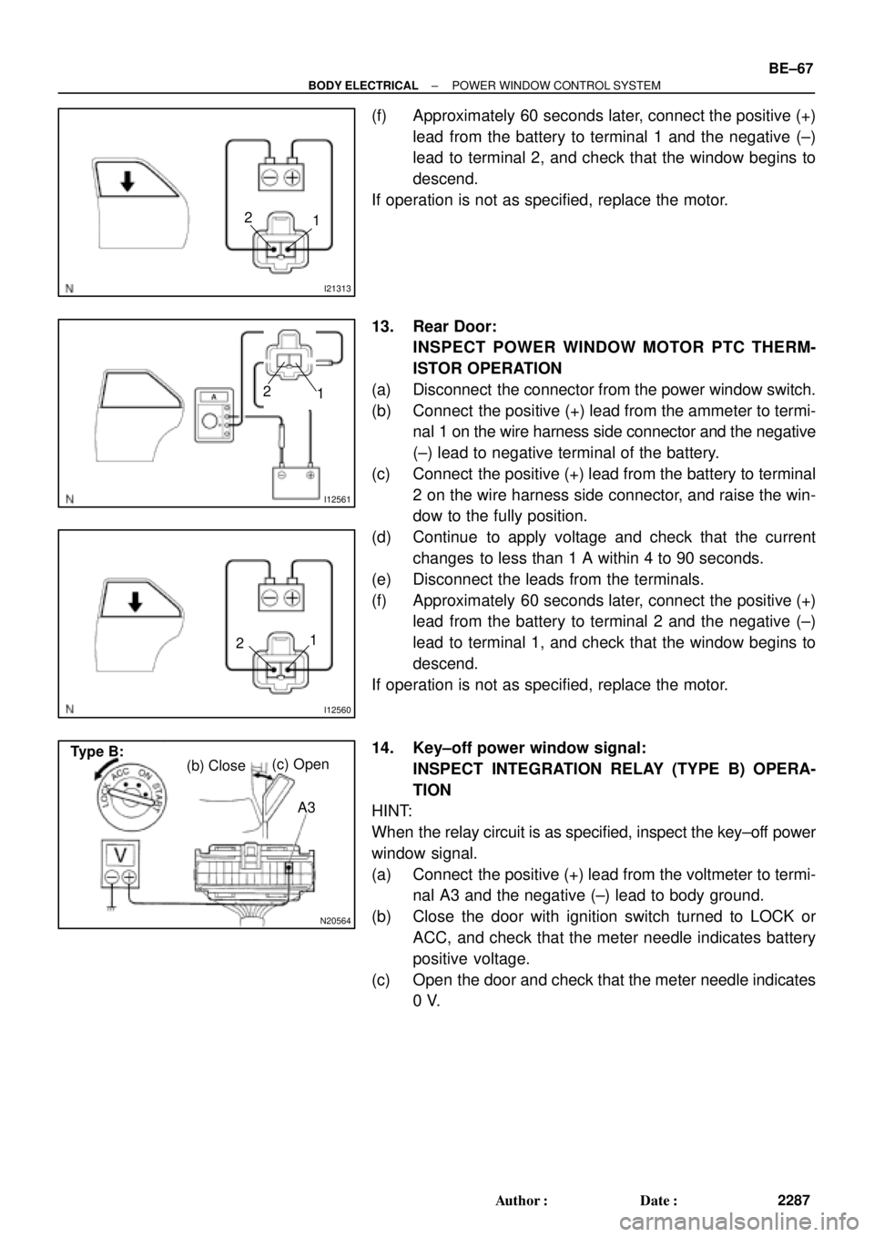
13. Rear Door:
INSPECT POWER WINDOW MOTOR PTC THERM-
ISTOR OPERATION
(a) Disconnect the connector from the power window switch.
(b) Connect the positive (+) lead from the ammeter to termi-
nal 1 on the wire harness side connector and the negative
(±) lead to negative terminal of the battery.
(c) Connect the positive (+) lead from the battery to terminal
2 on the wire harness side connector, and raise the win-
dow to the fully position.
(d) Continue to apply voltage and check that the current
changes to less than 1 A within 4 to 90 seconds.
(e) Disconnect the leads from the terminals.
(f) Approximately 60 seconds later, connect the positive (+)
lead from the battery to terminal 2 and the negative (±)
lead to terminal 1, and check that the window begins to
descend.
If operation is not as specified, replace the motor.
14. Key±off power window signal:
INSPECT INTEGRATION RELAY (TYPE B) OPERA-
TION
HINT:
When the relay circuit is as specified, inspect the key±off power
window signal.
(a) Connect the positive (+) lead from the voltmeter to termi-
nal A3 and the negative (±) lead to body ground.
(b) Close the door with ignition switch turned to LOCK or
ACC, and check that the meter needle indicates battery
positive voltage.
(c) Open the door and check that the meter needle indicates
0 V.
Page 649 of 4592

N20565
A3 Type B:
N20566
(b) Close (c) Open
A12 Type C:
N20567
A12 Type C: BE±68
± BODY ELECTRICALPOWER WINDOW CONTROL SYSTEM
2288 Author�: MH Date�: 3/7/02
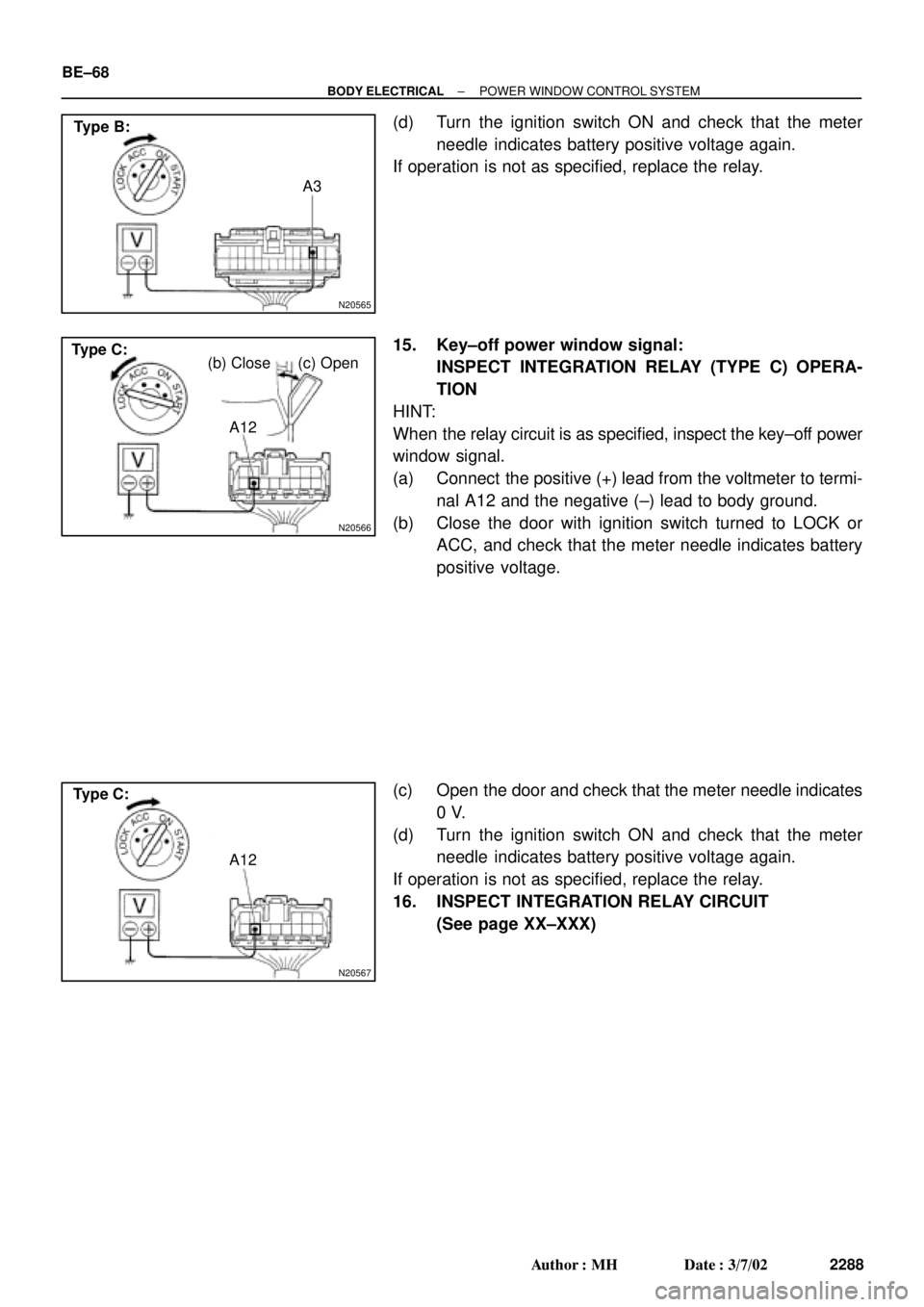
(d) Turn the ignition switch ON and check that the meter
needle indicates battery positive voltage again.
If operation is not as specified, replace the relay.
15. Key±off power window signal:
INSPECT INTEGRATION RELAY (TYPE C) OPERA-
TION
HINT:
When the relay circuit is as specified, inspect the key±off power
window signal.
(a) Connect the positive (+) lead from the voltmeter to termi-
nal A12 and the negative (±) lead to body ground.
(b) Close the door with ignition switch turned to LOCK or
ACC, and check that the meter needle indicates battery
positive voltage.
(c) Open the door and check that the meter needle indicates
0 V.
(d) Turn the ignition switch ON and check that the meter
needle indicates battery positive voltage again.
If operation is not as specified, replace the relay.
16. INSPECT INTEGRATION RELAY CIRCUIT
(See page XX±XXX)
Page 650 of 4592
BE0AP±02
Z19053
Instrument Panel J/B No.1
� POWER M±Fuse
� CIG Fuse
� DOOR Fuse
� Integration Relay
Power Window Master Switch
� Door Lock Control SwitchDoor Key Lock and Unlock Switch
Door Lock Assembly
� Door Lock Motor
� Door Unlock Detection Switch
Door Lock Assembly
� Door Lock Motor
� Door Unlock Detection Switch
Door Lock Control Switch
± BODY ELECTRICALPOWER DOOR LOCK CONTROL SYSTEM
BE±69
2289 Author�: Date�:
POWER DOOR LOCK CONTROL SYSTEM
LOCATION