Page 15 of 4592
± AIR CONDITIONINGTROUBLESHOOTING
AC±15
2497 Author�: Date�:
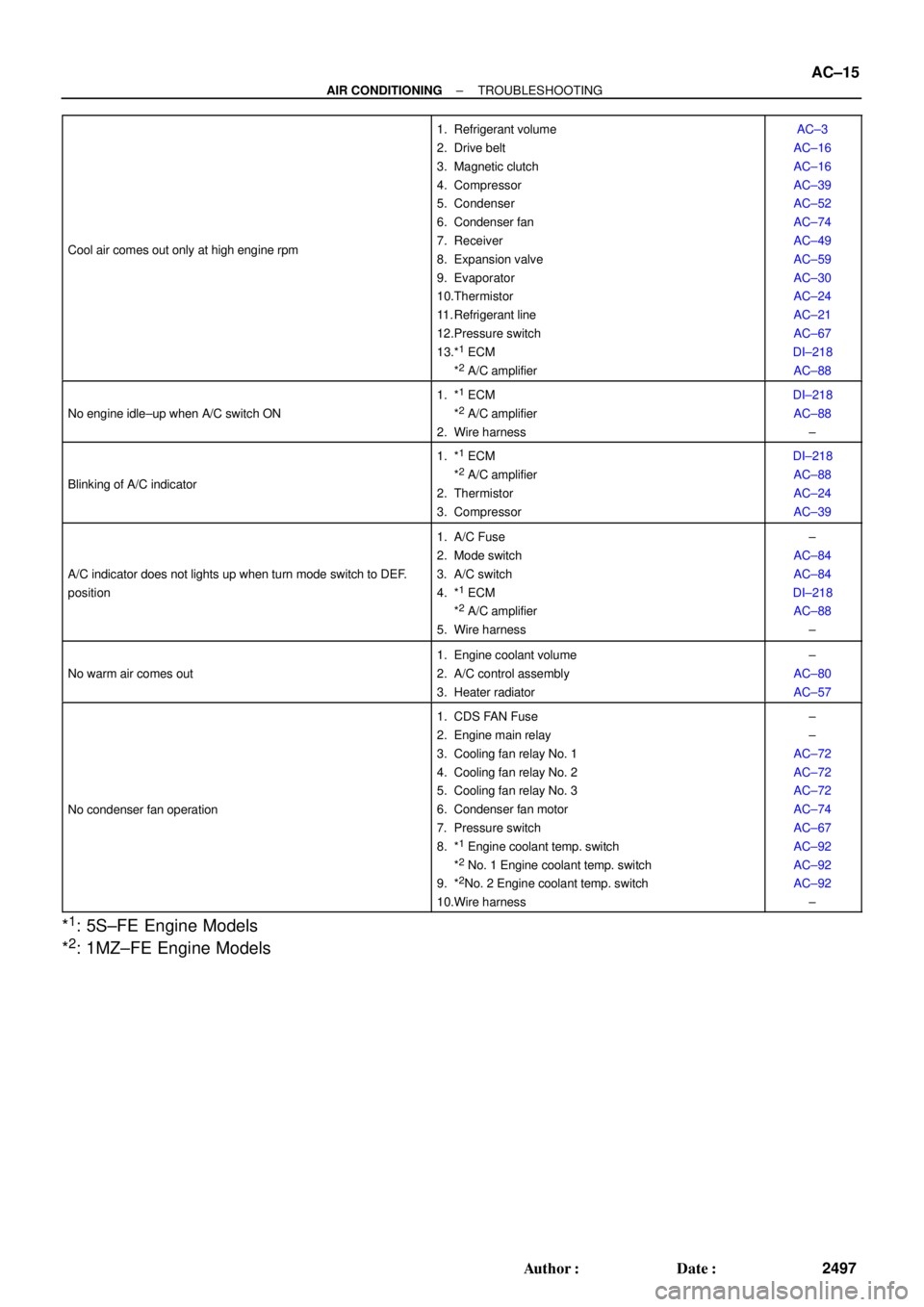
Cool air comes out only at high engine rpm
1. Refrigerant volume
2. Drive belt
3. Magnetic clutch
4. Compressor
5. Condenser
6. Condenser fan
7. Receiver
8. Expansion valve
9. Evaporator
10.Thermistor
11. Refrigerant line
12.Pressure switch
13.*
1 ECM
*2 A/C amplifier
AC±3
AC±16
AC±16
AC±39
AC±52
AC±74
AC±49
AC±59
AC±30
AC±24
AC±21
AC±67
DI±218
AC±88
No engine idle±up when A/C switch ON
1. *1 ECM
*2 A/C amplifier
2. Wire harness
DI±218
AC±88
±
Blinking of A/C indicator
1. *1 ECM
*2 A/C amplifier
2. Thermistor
3. Compressor
DI±218
AC±88
AC±24
AC±39
A/C indicator does not lights up when turn mode switch to DEF.
position
1. A/C Fuse
2. Mode switch
3. A/C switch
4. *
1 ECM
*2 A/C amplifier
5. Wire harness
±
AC±84
AC±84
DI±218
AC±88
±
No warm air comes out
1. Engine coolant volume
2. A/C control assembly
3. Heater radiator±
AC±80
AC±57
No condenser fan operation
1. CDS FAN Fuse
2. Engine main relay
3. Cooling fan relay No. 1
4. Cooling fan relay No. 2
5. Cooling fan relay No. 3
6. Condenser fan motor
7. Pressure switch
8. *
1 Engine coolant temp. switch
*2 No. 1 Engine coolant temp. switch
9. *2No. 2 Engine coolant temp. switch
10.Wire harness
±
±
AC±72
AC±72
AC±72
AC±74
AC±67
AC±92
AC±92
AC±92
±
*1: 5S±FE Engine Models
*
2: 1MZ±FE Engine Models
Page 73 of 4592
S05390
No. 1 Cooling
Fan Relay
AC226±01
S05387
No. 2 Cooling
Fan Relay
S05388
No. 3 Cooling
Fan Relay
Z12319
1
3
24
1
2 34
N23635
5 1 42
3 AC±72
± AIR CONDITIONINGCOOLING FAN RELAY
2554 Author�: Date�:
COOLING FAN RELAY
INSPECTION
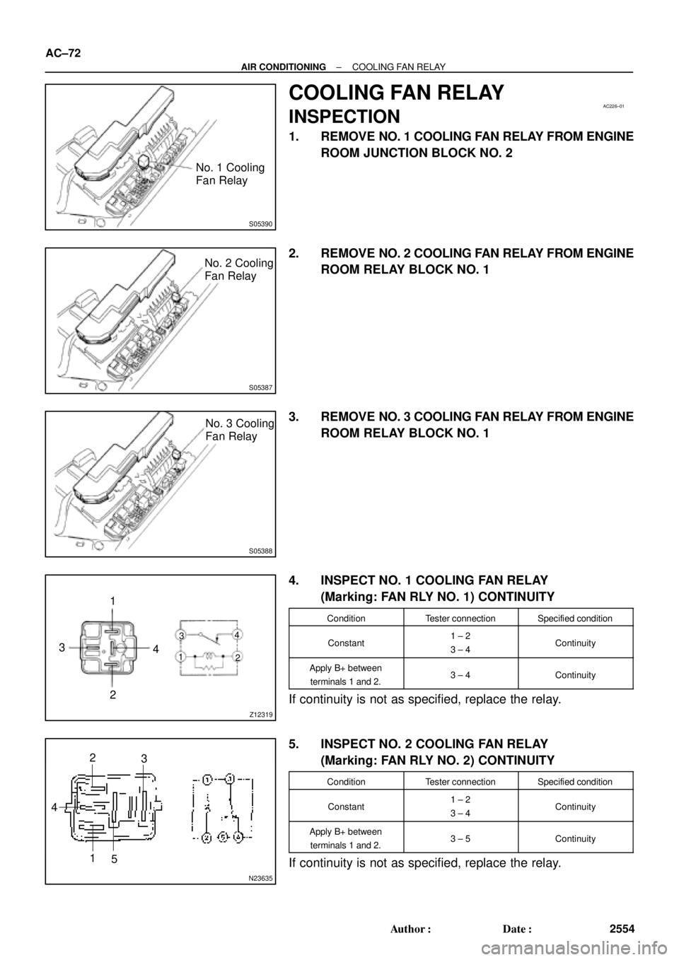
1. REMOVE NO. 1 COOLING FAN RELAY FROM ENGINE
ROOM JUNCTION BLOCK NO. 2
2. REMOVE NO. 2 COOLING FAN RELAY FROM ENGINE
ROOM RELAY BLOCK NO. 1
3. REMOVE NO. 3 COOLING FAN RELAY FROM ENGINE
ROOM RELAY BLOCK NO. 1
4. INSPECT NO. 1 COOLING FAN RELAY
(Marking: FAN RLY NO. 1) CONTINUITY
ConditionTester connectionSpecified condition
Constant1 ± 2
3 ± 4Continuity
Apply B+ between
terminals 1 and 2.3 ± 4Continuity
If continuity is not as specified, replace the relay.
5. INSPECT NO. 2 COOLING FAN RELAY
(Marking: FAN RLY NO. 2) CONTINUITY
ConditionTester connectionSpecified condition
Constant1 ± 2
3 ± 4Continuity
Apply B+ between
terminals 1 and 2.3 ± 5Continuity
If continuity is not as specified, replace the relay.
Page 74 of 4592
Z18060
12 3
5
12 3
5
± AIR CONDITIONINGCOOLING FAN RELAY
AC±73
2555 Author�: Date�:
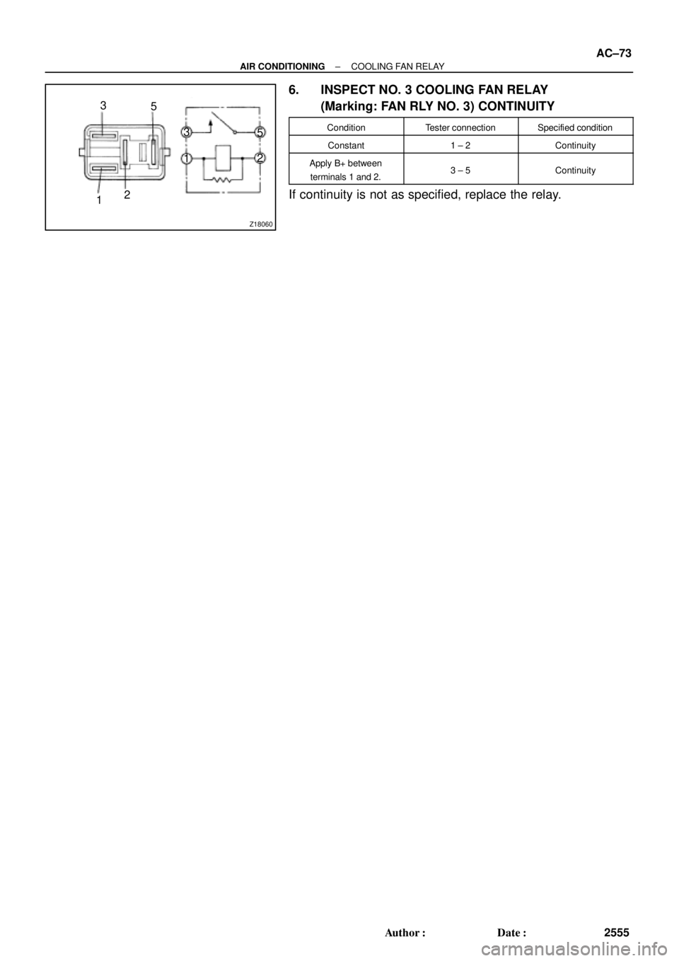
6. INSPECT NO. 3 COOLING FAN RELAY
(Marking: FAN RLY NO. 3) CONTINUITY
ConditionTester connectionSpecified condition
Constant1 ± 2Continuity
Apply B+ between
terminals 1 and 2.3 ± 5Continuity
If continuity is not as specified, replace the relay.
Page 75 of 4592
AC0N6±02
N20290
21
A AC±74
± AIR CONDITIONINGCONDENSER FAN
2556 Author�: Date�:
CONDENSER FAN
ON±VEHICLE INSPECTION
1. INSPECT CONDENSER FAN OPERATION
Inspect the fan operation, as shown in the chart below.
Test conditions:
�Ignition switch ON
�Blower speed control switch position ºHIº
�A/C switch ON
ConditionFan operation (Fan speed)
Engine coolant temperature
83°C (181°F) or belowNot rotate
Engine coolant temperature
98°C (208°F) or aboveRotate
Refrigerant pressure is less than
1,520 kPa (15.5 kgf/cm2, 220 psi)Not rotate (Low Speed)
Refrigerant pressure is 1,520 kPa
(15.5 kgf/cm2, 220 psi) or aboveRotate (High Speed)
If operation is not as specified, proceed next inspection.
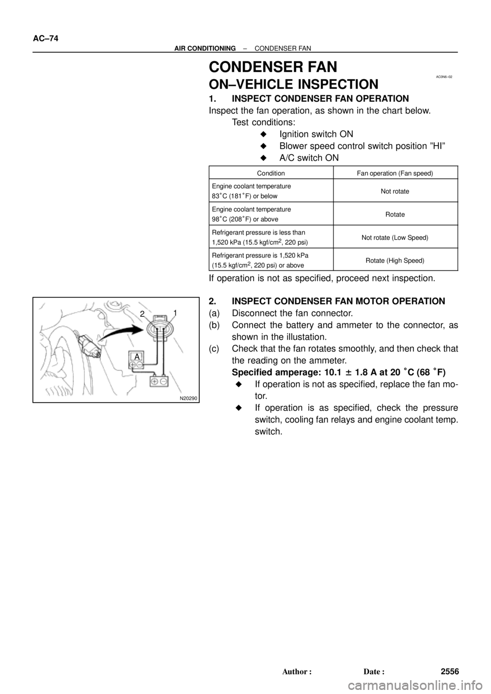
2. INSPECT CONDENSER FAN MOTOR OPERATION
(a) Disconnect the fan connector.
(b) Connect the battery and ammeter to the connector, as
shown in the illustation.
(c) Check that the fan rotates smoothly, and then check that
the reading on the ammeter.
Specified amperage: 10.1 ± 1.8 A at 20 °C (68 °F)
�If operation is not as specified, replace the fan mo-
tor.
�If operation is as specified, check the pressure
switch, cooling fan relays and engine coolant temp.
switch.
Page 1141 of 4592
CO066±03
± COOLING (5S±FE)COOLANT
CO±1
1575 Author�: Date�:
COOLANT
INSPECTION
HINT:
Check the coolant level when the engine is cold.
1. CHECK ENGINE COOLANT LEVEL AT RADIATOR RESERVOIR
The engine coolant level should be between the ºLOWº and ºFULLº lines.
If low, check for leaks and add ºToyota Long Life Coolantº or equivalent up to the ºFULLº line.
2. CHECK ENGINE COOLANT QUALITY
(a) Remove the radiator cap.
CAUTION:
To avoid the danger of being burned, do not remove the radiator cap while the engine and radiator
are still hot, as fluid and steam can be blown out under pressure.
(b) There should not be any excessive deposits of rust or scale around the radiator cap or radiator filler
hole, and the coolant should be free from oil.
If excessively dirty, replace the coolant.
(c) Reinstall the radiator cap.
Page 1142 of 4592
CO067±03
Z18990
Radiator Drain Plug
Engine Drain Plug CO±2
± COOLING (5S±FE)COOLANT
1576 Author�: Date�:
REPLACEMENT
1. DRAIN ENGINE COOLANT
(a) Remove the radiator cap.
CAUTION:
To avoid the danger of being burned, do not remove the ra-
diator cap while the engine and radiator are still hot, as fluid
and steam can be blown out under pressure.
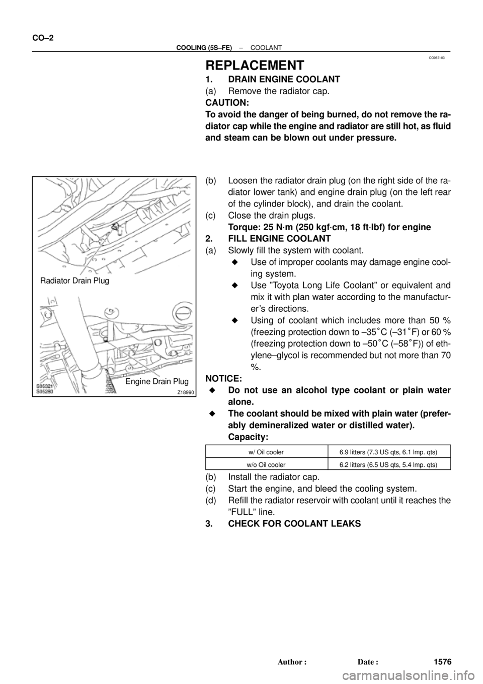
(b) Loosen the radiator drain plug (on the right side of the ra-
diator lower tank) and engine drain plug (on the left rear
of the cylinder block), and drain the coolant.
(c) Close the drain plugs.
Torque: 25 N´m (250 kgf´cm, 18 ft´lbf) for engine
2. FILL ENGINE COOLANT
(a) Slowly fill the system with coolant.
�Use of improper coolants may damage engine cool-
ing system.
�Use ºToyota Long Life Coolantº or equivalent and
mix it with plan water according to the manufactur-
er's directions.
�Using of coolant which includes more than 50 %
(freezing protection down to ±35°C (±31°F) or 60 %
(freezing protection down to ±50°C (±58°F)) of eth-
ylene±glycol is recommended but not more than 70
%.
NOTICE:
�Do not use an alcohol type coolant or plain water
alone.
�The coolant should be mixed with plain water (prefer-
ably demineralized water or distilled water).
Capacity:
w/ Oil cooler6.9 litters (7.3 US qts, 6.1 lmp. qts)
w/o Oil cooler6.2 litters (6.5 US qts, 5.4 lmp. qts)
(b) Install the radiator cap.
(c) Start the engine, and bleed the cooling system.
(d) Refill the radiator reservoir with coolant until it reaches the
ºFULLº line.
3. CHECK FOR COOLANT LEAKS
Page 1143 of 4592
CO068±03
S05543
Engine Moving Control Rod
No.2 RH Engine Mounting Bracket
Generator Drive Belt
w/ Oil Cooler
A/C Compressor
Connector
A/C Compressor
Cylinder Block Insulator
N´m (kgf´cm, ft´lbf)RH Front Fender Apron SealPS Pump Drive BeltGround Strap Connector
: Specified torque
64 (650, 47)
64 (650, 47)
52 (530, 38)
± COOLING (5S±FE)WATER PUMP
CO±3
1577 Author�: Date�:
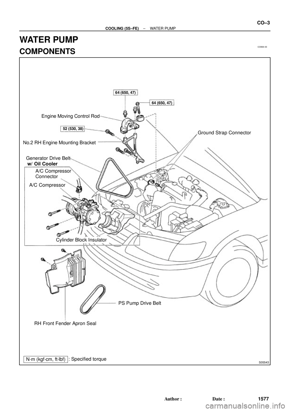
WATER PUMP
COMPONENTS
Page 1144 of 4592
S05939
No.2 Timing Belt
Cover
No.1 Timing Belt
Cover
Crankshaft
Pulley
No.2 Idler Pulley
Generator Drive Belt
Adjusting Bar
Wire Clamp
Crankshaft Position Sensor
Connector* Gasket
No.1 Idler Pulley
Tension Spring
� O±Ring
Water PumpWater PumpTiming Belt
Timing Belt Guide
Lower
Radiator
Hose Water Pump and
Water Pump Cover
Assembly High±Tension Cord Generator Wire
� Gasket Wire Clamp
Wire Clamp
Wire ClampWire Clamp Wire
Clamp
* GasketGenerator Connector
Generator
Spark Plug
� O±Ring
� Gasket
N´m (kgf´cm, ft´lbf): Specified torque
� Non±reusable part
108 (1,100, 80)18 (180,13)
42 (425,31)
42 (425,31)
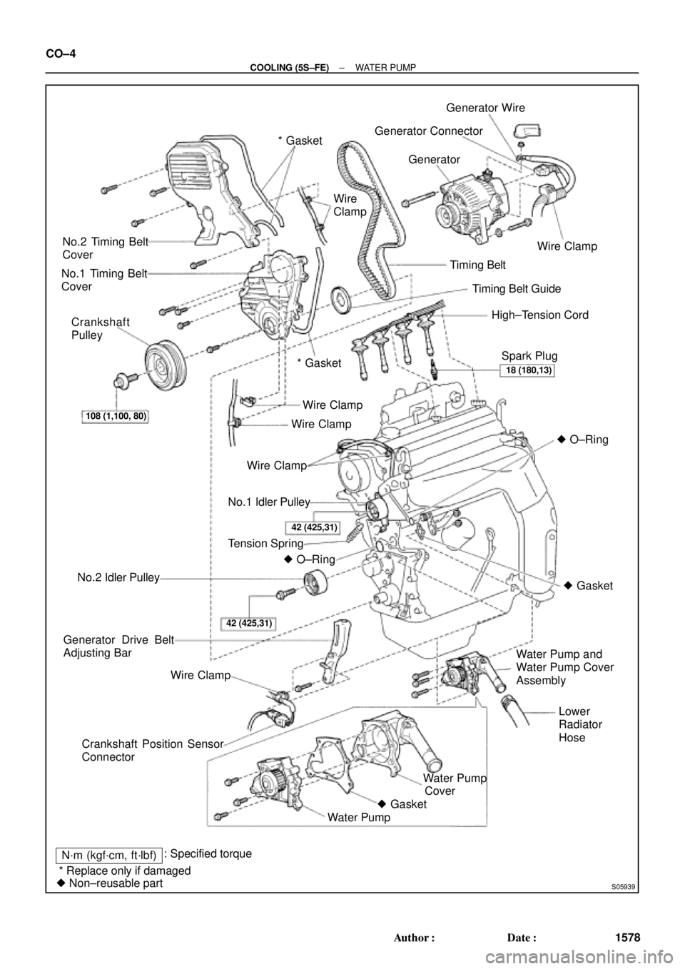
* Replace only if damagedCover CO±4
± COOLING (5S±FE)WATER PUMP
1578 Author�: Date�: