1999 TOYOTA CAMRY ESP
[x] Cancel search: ESPPage 4005 of 4592
Toyota Supports ASE CertificationPage 1 of 5
PG003-04Title:
REPAIR MANUAL CORRECTIONS INDEX
Models:
All ModelsTechnical Service
BULLETIN
May 18, 2004
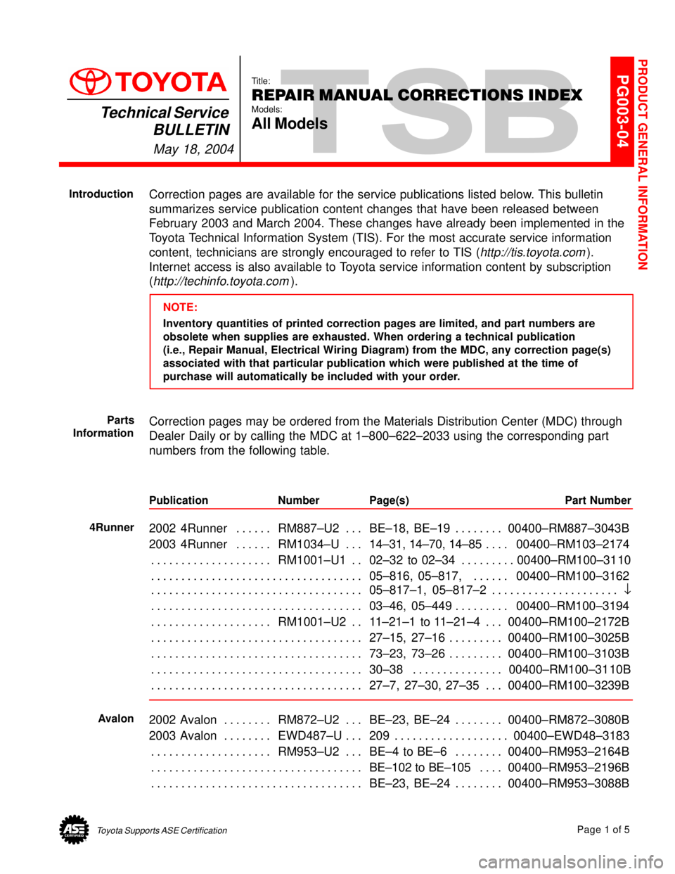
Correction pages are available for the service publications listed below. This bulletin
summarizes service publication content changes that have been released between
February 2003 and March 2004. These changes have already been implemented in the
Toyota Technical Information System (TIS). For the most accurate service information
content, technicians are strongly encouraged to refer to TIS (
http://tis.toyota.com).
Internet access is also available to Toyota service information content by subscription
(
http://techinfo.toyota.com).
NOTE:
Inventory quantities of printed correction pages are limited, and part numbers are
obsolete when supplies are exhausted. When ordering a technical publication
(i.e., Repair Manual, Electrical Wiring Diagram) from the MDC, any correction page(s)
associated with that particular publication which were published at the time of
purchase will automatically be included with your order.
Correction pages may be ordered from the Materials Distribution Center (MDC) through
Dealer Daily or by calling the MDC at 1±800±622±2033 using the corresponding part
numbers from the following table.
Publication Number Page(s) Part Number
2002 4Runner RM887±U2 BE±18, BE±19 00400±RM887±3043B. . . . . . . . . . . . . . . . .
2003 4Runner RM1034±U14±31, 14±70, 14±8500400±RM103±2174 . . . . . . . . . . . . .
RM1001±U1 02±32 to 02±34 00400±RM100±31 10 . . . . . . . . . . . . . . . . . . . . . . . . . . . . . . .
05±816, 05±817, 00400±RM100±3162 . . . . . . . . . . . . . . . . . . . . . . . . . . . . . . . . . . . . . . . . .
05±817±1, 05±817±2O . . . . . . . . . . . . . . . . . . . . . . . . . . . . . . . . . . . . . . . . . . . . . . . . . . . . . . . .
03±46, 05±449 00400±RM100±3194 . . . . . . . . . . . . . . . . . . . . . . . . . . . . . . . . . . . . . . . . . . . .
RM1001±U2 11±21±1 to 11±21±4 00400±RM100±2172B . . . . . . . . . . . . . . . . . . . . . . . . .
27±15, 27±16 00400±RM100±3025B . . . . . . . . . . . . . . . . . . . . . . . . . . . . . . . . . . . . . . . . . . . .
73±23, 73±26 00400±RM100±3103B . . . . . . . . . . . . . . . . . . . . . . . . . . . . . . . . . . . . . . . . . . . .
30±38 00400±RM100±31 10B . . . . . . . . . . . . . . . . . . . . . . . . . . . . . . . . . . . . . . . . . . . . . . . . . .
27±7, 27±30, 27±35 00400±RM100±3239B . . . . . . . . . . . . . . . . . . . . . . . . . . . . . . . . . . . . . .
2002 Avalon RM872±U2 BE±23, BE±24 00400±RM872±3080B. . . . . . . . . . . . . . . . . . .
2003 Avalon EWD487±U 209 00400±EWD48±3183. . . . . . . . . . . . . . . . . . . . . . . . . . . . . .
RM953±U2 BE±4 to BE±6 00400±RM953±2164B . . . . . . . . . . . . . . . . . . . . . . . . . . . . . . .
BE±102 to BE±10500400±RM953±2196B . . . . . . . . . . . . . . . . . . . . . . . . . . . . . . . . . . . . . . .
BE±23, BE±24 00400±RM953±3088B . . . . . . . . . . . . . . . . . . . . . . . . . . . . . . . . . . . . . . . . . . .
PRODUCT GENERAL INFORMATION
Introduction
Parts
Information
4Runner
Avalon
Page 4017 of 4592
B HOW TO USE THIS MANUAL
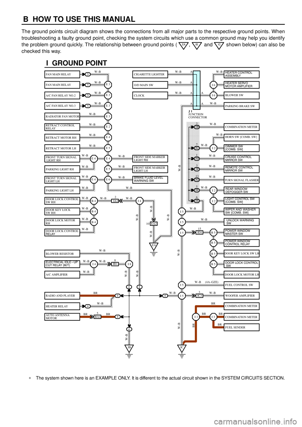
The ground points circuit diagram shows the connections from all major parts to the respective ground points. When
troubleshooting a faulty ground point, checking the system circuits which use a common ground may help you identify
the problem ground quickly. The relationship between ground points (
EA, IB and IC shown below) can also be
checked this way.
���� ���� ���� ���� ���� ���� ���� ���� ���� ���� ���� ���� ���� ���� ���� ���� ���� ���� ����
I GROUND POINT
FAN MAIN RELAY
FAN MAIN RELAY
A/C FAN RELAY NO.2
A/C FAN RELAY NO.3
RADIATOR FAN MOTOR
RETRACT CONTROL
RELAY
RETRACT MOTOR RH
RETRACT MOTOR LH
FRONT TURN SIGNAL
LIGHT RH
PARKING LIGHT RH
FRONT TURN SIGNAL
LIGHT LH
PARKING LIGHT LH
DOOR LOCK CONTROL
SW RH
DOOR KEY LOCK
SW RH
DOOR LOCK MOTOR
RH
BLOWER RESISTOR
A/C AMPLIFIER
RADIO AND PLAYER
HEATER RELAY
AUTO ANTENNA
MOTOR
BLOWER SW
PARKING BRAKE SW
COMBINATION METER
HORN SW [COMB. SW]
TURN SIGNAL FLASHER
DOOR KEY LOCK SW LH
DOOR LOCK MOTOR LH
FUEL CONTROL SW
WOOFER AMPLIFIER
COMBINATION METER
COMBINATION METER
FUEL SENDER
CIGARETTE LIGHTER
O/D MAIN SW
CLOCK
5
5
5
5
4
4
4
4
4BA15
IB18
EA2 10
3E5
3E
6 3G
13 3F
3 3D
1 3B
7
ID115
IC33
IA12
E 3
A
A AW±B
W±BW±B W±B
W±B W±B
W±B
W±B
W±B
W±B
W±B
W±B
W±B
W±B
W±B W±BW±B W±B W±B W±B
W±B W±B
W±BW±B
W±B
W±B
W±B W±B
W±B
BR
W±B
BR BRW±BW±B
W±B
W±B
W±B
W±B
W±B
W±B
W±B
W±B
W±B W±B
W±B
W±B
W±B
W±B
BR W±B
BR BR
BR W±B W±BW±B
W±BW±BBR W±B (4A±GZE)
W±B A A A
I 6
I 6
I 2
I 2
I 2
B 5I 5
I 5
I 5
B 5
B 5
B 5
I 5
I 5
I 3I 3
E 3
E 3
E 3
E 2
E 4
E 5
E 4
E 5
E 6E 4
E 4
B 4
EAI 4
B 4
B 4
I 4I 8
IBIC
3C7
4
JUNCTION
CONNECTOR J 1
4
DOOR LOCK CONTROL
RELAY
ELECTRICAL IDLE-UP
CUT RELAY (M/T)FRONT SIDE MARKER
LIGHT RH
FRONT SIDE MARKER
LIGHT LH
BRAKE FLUID LEVEL
WARNING SW
UNLOCK WARNING
SW WIPER AND WASHER
SW [COMB. SW] LIGHT CONTROL SW
[COMB. SW] HEATER CONTROL
ASSEMBLY
HEATER SERVO
MOTOR AMPLIFIER
DIMMER SW
[COMB. SW]
CRUISE CONTROL
MIRROR SW
REAR WINDOW
DEFOGGER SW
POWER WINDOW
MASTER SW
POWER WINDOW
CONTROL RELAY
DOOR LOCK CONTROL
SW
REMOTE CONTROL
MIRROR SW
*The system shown here is an EXAMPLE ONLY. It is different to the actual circuit shown in the SYSTEM CIRCUITS SECTION.
Page 4027 of 4592
E GLOSSARY OF TERMS AND SYMBOLS
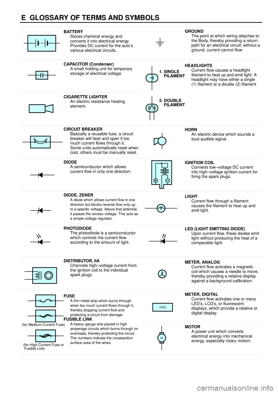
BATTERY
Stores chemical energy and
converts it into electrical energy.
Provides DC current for the auto's
various electrical circuits.GROUND
The point at which wiring attaches to
the Body, thereby providing a return
path for an electrical circuit; without a
ground, current cannot flow.
CAPACITOR (Condenser)
A small holding unit for temporary
storage of electrical voltage.HEADLIGHTS
Current flow causes a headlight
filament to heat up and emit light. A
headlight may have either a single
(1) filament or a double (2) filament
1. SINGLE
FILAMENT
CIGARETTE LIGHTER
An electric resistance heating
element.2. DOUBLE
FILAMENT
CIRCUIT BREAKER
Basically a reusable fuse, a circuit
breaker will heat and open if too
much current flows through it.
Some units automatically reset when
cool, others must be manually reset.HORN
An electric device which sounds a
loud audible signal.
DIODE
A semiconductor which allows
current flow in only one direction.IGNITION COIL
Converts low±voltage DC current
into high±voltage ignition current for
firing the spark plugs.
DIODE, ZENERA diode which allows current flow in one
direction but blocks reverse flow only up
to a specific voltage. Above that potential,
it passes the excess voltage. This acts as
a simple voltage regulator.LIGHT
Current flow through a filament
causes the filament to heat up and
emit light.
PHOTODIODE
The photodiode is a semiconductor
which controls the current flow
according to the amount of light.LED (LIGHT EMITTING DIODE)
Upon current flow, these diodes emit
light without producing the heat of a
comparable light.
DISTRIBUTOR, IIA
Channels high±voltage current from
the ignition coil to the individual
spark plugs.METER, ANALOG
Current flow activates a magnetic
coil which causes a needle to move,
thereby providing a relative display
against a background calibration.
FUSEA thin metal strip which burns through
when too much current flows through it,
thereby stopping current flow and
protecting a circuit from damage.
FUSIBLE LINK
METER, DIGITAL
Current flow activates one or many
LED's, LCD's, or fluorescent
displays, which provide a relative or
digital display.
FUEL
FUSIBLE LINK
A heavy±gauge wire placed in high
amperage circuits which burns through on
overloads, thereby protecting the circuit.
The numbers indicate the crosssection
surface area of the wires.(for Medium Current Fuse)
(for High Current Fuse or
Fusible Link)MOTOR
A power unit which converts
electrical energy into mechanical
energy, especially rotary motion.
M
Page 4069 of 4592

ENGINE CONTROL
2. CONTROL SYSTEM
*SFI system
The SFI system monitors the engine condition through the signals, which are input from each sensor to the engine
control module. The best fuel injection volume is decided based on this data and the program memorized by the engine
control module, and the control signal is output to TERMINALS #10+, #20+, #30+ and #40+ of the engine control
module to operate the injector. (Inject the fuel). The SFI system produces control of fuel injection operation by the engine
control module in response to the driving conditions.
*ESA system
The ESA system monitors the engine condition through the signals, which are input to the engine control module from
each sensor the best ignition timing is detected according to this data and the memorized data in the engine control
module, and the control signal is output to TERMINALS IGT1 and IGT2. This signal controls the igniter to provide the
best ignition timing for the driving conditions.
*IAC system
The IAC system (Step motor type) increases the RPM and provides idling stability for fast idle±up when the engine is
cold and when the idle speed has dropped due to electrical load, etc. The engine control module evaluates the signals
from each sensor, outputs current to TERMINAL RSD , and controls the idle air control valve.
*Fuel control system
The engine control module operation outputs to TERMINAL FC and controls the CIR OPN relay. Thus controls the fuel
shutoff valve open and close.
*EGR control system
The EGR control system controls the VSV (EGR) by evaluating the signals from each sensor which are input to the
engine control module and by sending output to TERMINAL EGR of the engine control module.
*A/C conditioning operation system
In addition to the conventional A/C cut control, the engine control module performs the air conditioning operation as well
since the A/C amplifier function is built in it.
3. DIAGNOSIS SYSTEM
With the diagnosis system, when there is a malfunctioning in the engine control module signal system, the malfunction
system is recorded in the memory. The malfunctioning system can then be found by reading the display (Code) of the
malfunction indicator lamp.
4. FAIL±SAFE SYSTEM
When a malfunction occurs in any system, if there is a possibility of engine trouble being caused by continued control based
on the signals from that system, the fail±safe system either controls the system by using data (Standard values) recorded in
the engine control module memory or else stops the engine.
E4 (A), E5 (B), E6 (C), E7 (D) ENGINE CONTROL MODULE
BATT±E1 : Always 9.0±14.0 volts
+B±E1 :9.0±14.0 volts with the ignition SW at ON or ST position
VC±E2 :4.5± 5.5 volts with the ignition SW on
VTA±E2 :0.3± 0.8 volts with the ignition SW on and throttle valve fully closed
3.2±4.9 volts with the ignition SW on and throttle valve open
PIM±E2 :3.3± 3.9 volts with the ignition SW on
THA±E2 :0.5±3.4 volts with the ignition SW on and intake air temp. 20°C (68°F)
THW±E2 :0.2± 1.0 volts with the ignition SW on and coolant temp. 80°C (176°F)
STA±E1 :6.0±14.0 volts with the engine cranking
W±E1 :9.0±14.0 volts with the no trouble and engine running
TE1±E1 :9.0±14.0 volts with the ignition SW on
NSW±E1 :0± 3.0 volts with the ignition SW on and Park/Neutral position SW position P or N position
9.0±14.0 volts with the ignition SW on and except Park/Neutral position SW position P or N position
IGT1, IGT2±E1 : Pulse generation with the engine cranking or idling
#10+, #20+, #30+, #40+±E01, E02 :9.0±14.0 volts with the ignition SW on
SERVICE HINTS
Page 4121 of 4592
ABS
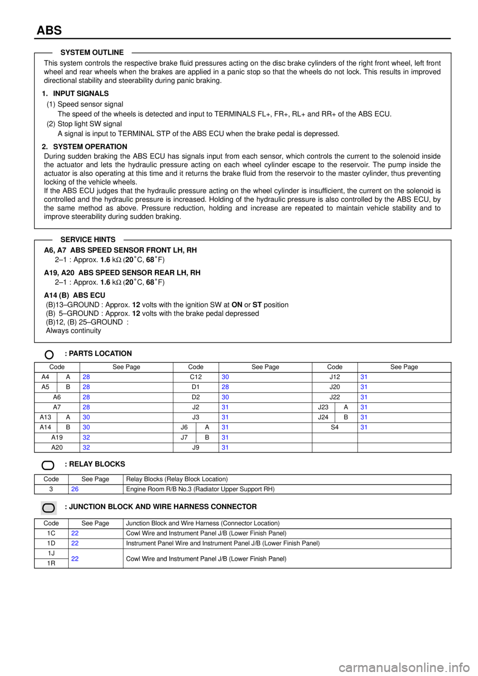
This system controls the respective brake fluid pressures acting on the disc brake cylinders of the right front wheel, left front
wheel and rear wheels when the brakes are applied in a panic stop so that the wheels do not lock. This results in improved
directional stability and steerability during panic braking.
1. INPUT SIGNALS
(1) Speed sensor signal
The speed of the wheels is detected and input to TERMINALS FL+, FR+, RL+ and RR+ of the ABS ECU.
(2) Stop light SW signal
A signal is input to TERMINAL STP of the ABS ECU when the brake pedal is depressed.
2. SYSTEM OPERATION
During sudden braking the ABS ECU has signals input from each sensor, which controls the current to the solenoid inside
the actuator and lets the hydraulic pressure acting on each wheel cylinder escape to the reservoir. The pump inside the
actuator is also operating at this time and it returns the brake fluid from the reservoir to the master cylinder, thus preventing
locking of the vehicle wheels.
If the ABS ECU judges that the hydraulic pressure acting on the wheel cylinder is insufficient, the current on the solenoid is
controlled and the hydraulic pressure is increased. Holding of the hydraulic pressure is also controlled by the ABS ECU, by
the same method as above. Pressure reduction, holding and increase are repeated to maintain vehicle stability and to
improve steerability during sudden braking.
A6, A7 ABS SPEED SENSOR FRONT LH, RH
2±1 : Approx. 1.6 kW (20°C, 68°F)
A19, A20 ABS SPEED SENSOR REAR LH, RH
2±1 : Approx. 1.6 kW (20°C, 68°F)
A14 (B) ABS ECU
(B)13±GROUND : Approx. 12 volts with the ignition SW at ON or ST position
(B) 5±GROUND : Approx. 12 volts with the brake pedal depressed
(B)12, (B) 25±GROUND :
Always continuity
: PARTS LOCATION
CodeSee PageCodeSee PageCodeSee Page
A4A28C1230J1231
A5B28D128J2031
A628D230J2231
A728J231J23A31
A13A30J331J24B31
A14B30J6A31S431
A1932J7B31
A2032J931
: RELAY BLOCKS
CodeSee PageRelay Blocks (Relay Block Location)
326Engine Room R/B No.3 (Radiator Upper Support RH)
������ ���: JUNCTION BLOCK AND WIRE HARNESS CONNECTOR
CodeSee PageJunction Block and Wire Harness (Connector Location)
1C22Cowl Wire and Instrument Panel J/B (Lower Finish Panel)
1D22Instrument Panel Wire and Instrument Panel J/B (Lower Finish Panel)
1J22Cowl Wire and Instrument Panel J/B (Lower Finish Panel)1R22Cowl Wire and Instrument Panel J/B (Lower Finish Panel)
SYSTEM OUTLINE
SERVICE HINTS
Page 4235 of 4592

B HOW TO USE THIS MANUAL
The ground points circuit diagram shows the connections from all major parts to the respective ground points. When
troubleshooting a faulty ground point, checking the system circuits which use a common ground may help you identify
the problem ground quickly. The relationship between ground points (
EA, IB and IC shown below) can also be
checked this way.
���� ���� ���� ���� ���� ���� ���� ���� ���� ���� ���� ���� ���� ���� ���� ���� ���� ���� ����
I GROUND POINT
FAN MAIN RELAY
FAN MAIN RELAY
A/C FAN RELAY NO.2
A/C FAN RELAY NO.3
RADIATOR FAN MOTOR
RETRACT CONTROL
RELAY
RETRACT MOTOR RH
RETRACT MOTOR LH
FRONT TURN SIGNAL
LIGHT RH
PARKING LIGHT RH
FRONT TURN SIGNAL
LIGHT LH
PARKING LIGHT LH
DOOR LOCK CONTROL
SW RH
DOOR KEY LOCK
SW RH
DOOR LOCK MOTOR
RH
BLOWER RESISTOR
A/C AMPLIFIER
RADIO AND PLAYER
HEATER RELAY
AUTO ANTENNA
MOTOR
BLOWER SW
PARKING BRAKE SW
COMBINATION METER
HORN SW [COMB. SW]
TURN SIGNAL FLASHER
DOOR KEY LOCK SW LH
DOOR LOCK MOTOR LH
FUEL CONTROL SW
WOOFER AMPLIFIER
COMBINATION METER
COMBINATION METER
FUEL SENDER
CIGARETTE LIGHTER
O/D MAIN SW
CLOCK
5
5
5
5
4
4
4
4
4BA15
IB18
EA2 10
3E5
3E
6 3G
13 3F
3 3D
1 3B
7
ID115
IC33
IA12
E 3
A
A AW±B
W±BW±B W±B
W±B W±B
W±B
W±B
W±B
W±B
W±B
W±B
W±B
W±B
W±B W±BW±B W±B W±B W±B
W±B W±B
W±BW±B
W±B
W±B
W±B W±B
W±B
BR
W±B
BR BRW±BW±B
W±B
W±B
W±B
W±B
W±B
W±B
W±B
W±B
W±B W±B
W±B
W±B
W±B
W±B
BR W±B
BR BR
BR W±B W±BW±B
W±BW±BBR W±B (4A±GZE)
W±B A A A
I 6
I 6
I 2
I 2
I 2
B 5I 5
I 5
I 5
B 5
B 5
B 5
I 5
I 5
I 3I 3
E 3
E 3
E 3
E 2
E 4
E 5
E 4
E 5
E 6E 4
E 4
B 4
EAI 4
B 4
B 4
I 4I 8
IBIC
3C7
4
JUNCTION
CONNECTOR J 1
4
DOOR LOCK CONTROL
RELAY
ELECTRICAL IDLE-UP
CUT RELAY (M/T)FRONT SIDE MARKER
LIGHT RH
FRONT SIDE MARKER
LIGHT LH
BRAKE FLUID LEVEL
WARNING SW
UNLOCK WARNING
SW WIPER AND WASHER
SW [COMB. SW] LIGHT CONTROL SW
[COMB. SW] HEATER CONTROL
ASSEMBLY
HEATER SERVO
MOTOR AMPLIFIER
DIMMER SW
[COMB. SW]
CRUISE CONTROL
MIRROR SW
REAR WINDOW
DEFOGGER SW
POWER WINDOW
MASTER SW
POWER WINDOW
CONTROL RELAY
DOOR LOCK CONTROL
SW
REMOTE CONTROL
MIRROR SW
* The system shown here is an EXAMPLE ONLY. It is different to the actual circuit shown in the SYSTEM CIRCUITS SECTION.
Page 4243 of 4592
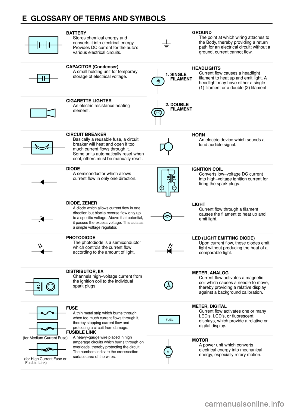
E GLOSSARY OF TERMS AND SYMBOLS
BATTERY
Stores chemical energy and
converts it into electrical energy.
Provides DC current for the auto's
various electrical circuits.GROUND
The point at which wiring attaches to
the Body, thereby providing a return
path for an electrical circuit; without a
ground, current cannot flow.
CAPACITOR (Condenser)
A small holding unit for temporary
storage of electrical voltage.HEADLIGHTS
Current flow causes a headlight
filament to heat up and emit light. A
headlight may have either a single
(1) filament or a double (2) filament
1. SINGLE
FILAMENT
CIGARETTE LIGHTER
An electric resistance heating
element.2. DOUBLE
FILAMENT
CIRCUIT BREAKER
Basically a reusable fuse, a circuit
breaker will heat and open if too
much current flows through it.
Some units automatically reset when
cool, others must be manually reset.HORN
An electric device which sounds a
loud audible signal.
DIODE
A semiconductor which allows
current flow in only one direction.IGNITION COIL
Converts low±voltage DC current
into high±voltage ignition current for
firing the spark plugs.
DIODE, ZENERA diode which allows current flow in one
direction but blocks reverse flow only up
to a specific voltage. Above that potential,
it passes the excess voltage. This acts as
a simple voltage regulator.LIGHT
Current flow through a filament
causes the filament to heat up and
emit light.
PHOTODIODE
The photodiode is a semiconductor
which controls the current flow
according to the amount of light.LED (LIGHT EMITTING DIODE)
Upon current flow, these diodes emit
light without producing the heat of a
comparable light.
DISTRIBUTOR, IIA
Channels high±voltage current from
the ignition coil to the individual
spark plugs.METER, ANALOG
Current flow activates a magnetic
coil which causes a needle to move,
thereby providing a relative display
against a background calibration.
FUSEA thin metal strip which burns through
when too much current flows through it,
thereby stopping current flow and
protecting a circuit from damage.
FUSIBLE LINK
METER, DIGITAL
Current flow activates one or many
LED's, LCD's, or fluorescent
displays, which provide a relative or
digital display.
FUEL
FUSIBLE LINK
A heavy±gauge wire placed in high
amperage circuits which burns through on
overloads, thereby protecting the circuit.
The numbers indicate the crosssection
surface area of the wires.(for Medium Current Fuse)
(for High Current Fuse or
Fusible Link)MOTOR
A power unit which converts
electrical energy into mechanical
energy, especially rotary motion.
M
Page 4299 of 4592

ENGINE CONTROL (1MZ±FE)
2. CONTROL SYSTEM
*SFI system
The SFI system monitors the engine condition through the signals, which are input from each sensor (Input signals (1) to
(12) ). The best fuel injection volume is decided based on this data and the program memorized by the engine control
module, and the control signal is output to TERMINALS #10, #20, #30, #40, #50 and #60 of the engine control module
to operate the injector (Inject the fuel). The SFI system produces control of fuel injection operation by the engine control
module in response to the driving conditions.
*ESA system
The ESA system monitors the engine condition through the signals, which are input to the engine control module from
each sensor (Input signals from 1, 3, 4, 12). The best ignition timing is decided according to this data and the memorized
data in the engine control module and the control signal is output to TERMINALS IGT1, IGT2 and IGT3. This signal
controls the igniter to provide the best ignition timing for the driving conditions.
*Heated oxygen sensor heater control system
The heated oxygen sensor heater control system turns the heater on when the intake air volume is low (Temp. of
exhaust emissions is low), and warms up the heated oxygen sensor to improve detection performance of the sensor.
The engine control module evaluates the signals from each sensor (Input signals from 1, 4, 9, 10), current is output to
TERMINALS HTL, HTR and HTS, controlling the heater.
*Idle air control system
The idle air control system (Rotary solenoid type) increases the RPM and provides idle stability for fast idle±up when the
engine is cold, and when the idle speed has dropped due to electrical load and so on, the engine control module
evaluates the signals from each sensor (Input signals from 1, 4, 5, 8, 9), current is output to TERMINALS RSO and RSC
to control idle air control valve.
*EGR control system
The EGR control system detects the signal from each sensor (Input signals from 1, 4, 9, 10), and outputs current to
TERMINAL EGR to control the VSV (EGR).
The EGR valve position sensor is mounted on the EGR valve. this sensor converts the EGR valve opening height into a
voltage and sends it to the engine control module as the EGR valve position signal.
*ACIS
ACIS includes a valve in the bulkhead separating the surge tank into two parts. This valve is opened and closed in
accordance with the driving conditions to control the intake manifold length in two stages for increased engine output in
all ranges from low to high speeds.
The engine control module judges the engine speed by the signals ( (4), (5) ) from each sensor and outputs signals to
the TERMINAL ACIS to control the VSV (Intake air control).
3. DIAGNOSIS SYSTEM
With the diagnosis system, when there is a malfunction in the engine control module signal system, the malfunctioning
system is recorded in the memory.
4. FAIL±SAFE SYSTEM
When a malfunction occurs in any systems, if there is a possibility of engine trouble being caused by continued control
based on the signals from that system, the fail±safe system either controls the system by using data (Standard values)
recorded in the engine control module memory or else stops the engine.