Page 22 of 349

B07465
New
Previous
– INTRODUCTIONFOR ALL OF VEHICLES
IN–17
5. FOR VEHICLES EQUIPPED WITH POWER WINDOW CONTROL SYSTEM
When the battery is disconnected or the power to the window regulator motor is cut, the power window con-
trol system does not operate. It is necessary to initialize the system in the following procedures. Otherwise
window cannot be operated normally.
(1) Close window to the highest position.
(2) Keep holding the switch for 5 seconds.
(3) Check that automatic operation works. If not, repeat the above procedures.
6. FOR VEHICLES EQUIPPED WITH SLIDING ROOF SYSTEM
Sliding roof stop position might be required to be initialized when battery failures (such as battery disconnec-
tion, connector disconnection and the voltage drop) are detected while the system is in operation. This also
occurs when rotating the motor with the battery disconnected. Sliding roof initialization can be done by the
following procedures.
(1) Operate the roof up to the maximum tilt position.
(2) Release the switch, and push it again in the same direction. (After 10 seconds have elapsed,
initialization begins.)
(3) The roof starts automatic operation if holding the switch, completes full one cycle (tilt down, slide
open, slide close and tilt up) of travel. Do not release the switch until the roof stops.
(4) Check that the roof stops at the correct position.
7. FOR VEHICLES EQUIPPED WITH BRAKE PIPE FIT-
TING OF NEW STANDARD
A flare shape of a new standard is used for the brake pipe fitting
from this changed models.
NOTICE:
�When ordering or replacing the parts, please be sure
to check and use the fitting of the same flare type.
�Do not over–tighten them more than the standard
torque.
Torque: 15 N·m (155 kgf·cm, 11 ft·lbf)
Page 25 of 349

Important Points in the Customer Problem Analysis
� What ––––– Vehicle model, system name
� When ––––– Date, time, occurrence frequency
� Where ––––– Road conditions
� Under what conditions? ––––– Running conditions, driving conditions, weather conditions
� How did it happen? ––––– Problem symptoms
(Sample) Supplemental restraint system check sheet.
Supplemental Restraint System Check Sheet
Customer’s Name
Date Vehicle Brought In
Registration No.
Frame No.
Odometer Reading
km
miles
Date Problem First Occurred
Weather
Temperature
Vehicle OperationFine Cloudy
StartingIdling
Driving
Constant speed Acceleration
OtherInspector’s
Name
CUSTOMER PROBLEM ANALYSIS CHECK
Registration Year
RainySnowyOther / / / /
/ /
Approx.
Deceleration [
]
IN–20– INTRODUCTIONHOW TO TROUBLESHOOT ECU CONTROLLED
SYSTEMS
1. CUSTOMER PROBLEM ANALYSIS
In troubleshooting, the problem symptoms must be confirmed accurately and all preconceptions must be
cleared away in order to give an accurate judgement. To ascertain just what the problem symptoms are, it
is extremely important to ask the customer about the problem and the conditions at the time it occurred.
Important Point in the Problem Analysis:
The following 5 items are important points in the problem analysis. Past problems which are thought to be
unrelated and the repair history, etc. may also help in some cases, so as much information as possible should
be gathered and its relationship with the problem symptoms should be correctly ascertained for reference
in troubleshooting. A customer problem analysis table is provided in DI section for each system for your use.
Page 241 of 349

RS0IS–01
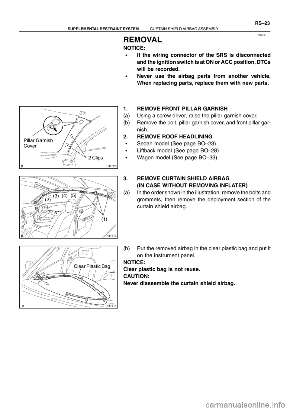
H11626
2 Clips
Pillar Garnish
Cover
H11613
(1)
(2)(3)(4)(5)
H11614
Clear Plastic Bag
– SUPPLEMENTAL RESTRAINT SYSTEMCURTAIN SHIELD AIRBAG ASSEMBLY
RS–23
REMOVAL
NOTICE:
�If the wiring connector of the SRS is disconnected
and the ignition switch is at ON or ACC position, DTCs
will be recorded.
�Never use the airbag parts from another vehicle.
When replacing parts, replace them with new parts.
1. REMOVE FRONT PILLAR GARNISH
(a) Using a screw driver, raise the pillar garnish cover.
(b) Remove the bolt, pillar garnish cover, and front pillar gar-
nish.
2. REMOVE ROOF HEADLINING
�Sedan model (See page BO–23)
�Liftback model (See page BO–28)
�Wagon model (See page BO–33)
3. REMOVE CURTAIN SHIELD AIRBAG
(IN CASE WITHOUT REMOVING INFLATER)
(a) In the order shown in the illustration, remove the bolts and
grommets, then remove the deployment section of the
curtain shield airbag.
(b) Put the removed airbag in the clear plastic bag and put it
on the instrument panel.
NOTICE:
Clear plastic bag is not reuse.
CAUTION:
Never diassemble the curtain shield airbag.