Page 11 of 349

IN0253
WRONG CORRECT
IN0252
WRONG CORRECT
IN0002
Example IN–6
– INTRODUCTIONREPAIR INSTRUCTIONS
(2) After the vehicle is jacked up, be sure to support it
on stands. It is extremely dangerous to do any work
on a vehicle raised on a jack alone, even for a small
job that can be finished quickly.
(l) Observe the following precautions to avoid damage to the
following parts:
(1) Do not open the cover or case of the ECU unless
absolutely necessary. (If the IC terminals are
touched, the IC may be destroyed by static electric-
ity.)
(2) To disconnect vacuum hoses, pull off the end, not
the middle of the hose.
(3) To pull apart electrical connectors, pull on the con-
nector itself, not the wires.
(4) Be careful not to drop electrical components, such
as sensors or relays. If they are dropped on a hard
floor, they should be replaced and not reused.
(5) When steam cleaning an engine, protect the elec-
tronic components, air filter and emission–related
components from water.
(6) Never use an impact wrench to remove or install
temperature switches or temperature sensors.
(7) When checking continuity at the wire connector, in-
sert the tester probe carefully to prevent terminals
from bending.
(8) When using a vacuum gauge, never force the hose
onto a connector that is too large. Use a step–down
adapter for adjustment. Once the hose has been
stretched, it may leak air.
(m) Installation and removal of vacuum hose:
(1) When disconnecting vacuum hoses, use tags to
identify where they should be reconnected to.
(2) After completing a job, double check that the vacu-
um hoses are properly connected. A label under the
hood shows the proper layout.
(n) Unless otherwise stated, all resistance is measured at an
ambient temperature of 20
C (68
F). Because the resis-
tance may be outside specifications if measured at high
temperatures immediately after the vehicle has been run-
ning, measurement should be made when the engine has
cooled down.
Page 274 of 349
BO0IO–04
I12751
Roof Headlining
Sun Visor Opening Trim
Holder Front Pillar Garnish
� Windshield
Outside Moulding
Front Pillar Garnish Windshield Wiper Arm
N·m (kgf·cm, ft·lbf) : Specified torque
� Non–reusable partWiper Arm
Sun Visor
20 (205, 15)
20 (205, 15)
� Dam Inner Rear View Mirror
Cowl Louver Map Light Assembly
Cap
Hood to Cowl Top seal � Stopper
w/ Curtain shield air bag:
Front Pillar Garnish
w/ Curtain shield air bag:
Front Pillar Garnish
– BODYWINDSHIELD
BO–3
WINDSHIELD
COMPONENTS
Page 287 of 349

BO2J3–01
I12491
H03659
H03660
: 4 Clips BO–16
– BODYINSTRUMENT PANEL
REMOVAL
1. REMOVE THESE PARTS:
(a) Remove the front door opening trims.
(b) Remove the front pillar garnishes.
(c) w/ Curtain Shield Airbag:
(1) Remove the 2 bolts.
(2) Pack the airbag with protection cover.
(3) Using a screwdriver, raise the pillar garnish cover.
(4) Remove the bolt, pillar garnish cover and front pillar
garnish.
NOTICE:
Protection rang is from instrument panel to ceiling.
(d) Remove the front door scuff plates.
(e) Remove the cowl side trims.
(f) Remove the rear door opening trims.
(g) Remove the rear door scuff plates.
(h) Remove the center pillar lower covers.
(i) Remove the front seats.
2. REMOVE STEERING WHEEL
(See Pub. No.RM599E on page SR–13)
3. REMOVE LOWER FINISH PANEL
(a) Remove the 2 screws and hood lock control lever.
(b) Remove the 2 screws and lower finish panel.
4. REMOVE THESE PARTS:
(See Pub. No.RM599E on page SR–13)
(a) Remove the column cover.
(b) Remove the combination switch.
(c) Remove the steering column.
5. REMOVE CLUSTER FINISH PANEL
(a) Remove the 2 screws.
(b) Using a screwdriver, remove the cluster finish panel, then
disconnect the connector.
HINT:
Tape the screwdriver tip before use.
6. REMOVE COMBINATION METER
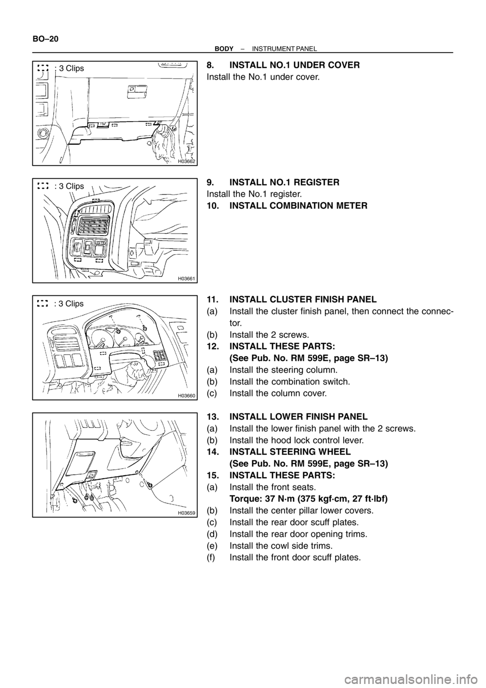
Page 291 of 349

H03662
: 3 Clips
H03661
: 3 Clips
H03660
: 3 Clips
H03659
BO–20
– BODYINSTRUMENT PANEL
8. INSTALL NO.1 UNDER COVER
Install the No.1 under cover.
9. INSTALL NO.1 REGISTER
Install the No.1 register.
10. INSTALL COMBINATION METER
11. INSTALL CLUSTER FINISH PANEL
(a) Install the cluster finish panel, then connect the connec-
tor.
(b) Install the 2 screws.
12. INSTALL THESE PARTS:
(See Pub. No. RM 599E, page SR–13)
(a) Install the steering column.
(b) Install the combination switch.
(c) Install the column cover.
13. INSTALL LOWER FINISH PANEL
(a) Install the lower finish panel with the 2 screws.
(b) Install the hood lock control lever.
14. INSTALL STEERING WHEEL
(See Pub. No. RM 599E, page SR–13)
15. INSTALL THESE PARTS:
(a) Install the front seats.
Torque: 37 N·m (375 kgf·cm, 27 ft·lbf)
(b) Install the center pillar lower covers.
(c) Install the rear door scuff plates.
(d) Install the rear door opening trims.
(e) Install the cowl side trims.
(f) Install the front door scuff plates.