Page 83 of 349

Drive belt deflect")
SS0IF–02
– SERVICE SPECIFICATIONSSTEERING
SS–13
STEERING
SERVICE DATA
DRIVE BELT
4A–FE and 7A–FE engines:
Drive belt deflection New belt5 – 6 mm (0.20 – 0.24 in.)
Drive belt deflection Used belt6 – 8 mm (0.24 – 0.31 in.)
*Drive belt tension New belt441 – 539 N (45 –55 kgf)
*Drive belt tension Used belt245 – 392 N (25 – 40 kgf)
3S–FE engine:
Drive belt deflection New belt8 – 10 mm (0.31 – 0.39 in.)
Drive belt deflection Used belt10 – 13 mm (0.39 – 0.51 in.)
* Drive belt tension New belt441 – 539 N (45 – 55 kgf)
* Drive belt tension Used belt245 – 392 N (25 – 40 kgf)
2C–T, 2C–TE and 1CD–FTV engines:
Drive belt deflection New belt11 – 14 mm (0.43 – 0.55 in.)
Drive belt deflection Used belt15 – 18 mm (0.59 – 0.71 in.)
* Drive belt tension New belt539 – 637 N (55 – 65 kgf)
* Drive belt tension Used belt245 – 392 N (25 – 40 kgf)
POWER STEERING FLUID
Oil level rise Maximum5 mm (0.20 in.)
4A–FE and 7A–FE engines:
Oil pressure at idle speed with valve closed Minimum8,238 kPa (84 kgf/cm2, 1,195 psi)
3S–FE engine:
Oil pressure at idle speed with valve closed Minimum9,022 kPa (92 kgf/cm2, 1,309 psi)
2C–T, 2C–TE and 1CD–FTV engines:
Oil pressure at idle speed with valve closed Minimum8,826 kPa (90 kgf/cm2, 1,280 psi)
PS VANE PUMP (2C–T, 2C–TE and 1CD–FTV engines)
Pump rotating torque Maximum0.3 N·m (2.8 kgf·cm, 2.4 in.·lbf)
Pump shaft and front housing bushing oil clearance STD
Maximum0.01 – 0.03 mm (0.0004 – 0.0012 in.)
0.07 mm (0.0028 in.)
Vane plate height Minimum8.1 mm (0.319 in.)
Vane plate thickness Minimum1.797 mm (0.0708 in.)
Vane plate length Minimum14.988 mm (0.5901 in.)
Vane plate and pump rotor groove clearance Maximum0.03 mm (0.0012 in.)
Vane plate length Pump rotor and cam ring mark
None14.996 – 14.998 mm (0.59039 – 0.59047 in.)
114.994 – 14.996 mm (0.59032 – 0.59039 in.)
214.992 – 14.994 mm (0.59024 – 0.59032 in.)
314.990 – 14.992 mm (0.59016 – 0.59024 in.)
414.988 – 14.990 mm (0.59008 – 0.59016 in.)
Flow control valve spring length Minimum36.0 mm (1.417 in.)
*: For use with belt tension gauge
Page 84 of 349
SS0IG–02
SS–14
– SERVICE SPECIFICATIONSSTEERING
TORQUE SPECIFICATION
Part tightenedN·mkgf·cmft·lbf
PS VANE PUMP (2C–T, 2C–TE and 1CD–FTV engines)
Pressure port union x Front housing6970051
Suction port union set bolt131309
Pulley cover x PS vane pump assembly3940029
PS vane pump assembly set bolt3940029
Union bolt x Pressure feed tube5252538
PS vane pump pulley set nut4344032
Idler pulley set nut3839028
Page 129 of 349
MX096–02
D06619
Starter
39 (400, 29)
Clutch Release
Cylinder
and Line
12 (120, 9)
4.9 (50, 43 in.·lbf)
12 (120, 9)
Control CableClip
Clip
Washer Air Flow Meter
ConnectorAir Cleaner Case
Assembly
with Air Hose
52 (530, 38)
87 (890, 64)
Engine Left
Mounting Bracket
Battery
Tray
No.1 Air Tube Assembly
Diesel Throttle Body
with No.2 Air Tube Assembly
Stay
VSV Connector for EGR
Turbo Pressure
Sensor Connector
Intake Air Temperature
Sensor Connector
Throttle Full
Switch Connector
Throttle Control
Motor Connector
� Gasket
� Non–reusable part
21 (214, 15)
N·m (kgf·cm, ft·lbf): Specified torque
15 (153, 11)
25 (255, 18)
25 (255, 18)
25 (255, 18)
25 (255, 18)
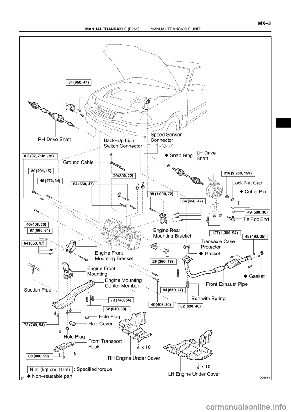
MX–2
– MANUAL TRANSAXLE (E251)MANUAL TRANSAXLE UNIT
MANUAL TRANSAXLE UNIT
COMPONENTS
Page 130 of 349
D06618
RH Drive Shaft
LH Drive
Shaft
216 (2,200, 159)
Lock Nut Cap
� Cotter Pin � Snap Ring
Front Exhaust Pipe
Engine Mounting
Center Member
LH Engine Under Cover RH Engine Under Cover
64 (650, 47)
Transaxle Case
Protector
25 (250, 18)
Back–Up Light
Switch Connector
Speed Sensor
Connector
Front Transport
HookHole Plug
Hole PlugHole Cover
64 (650, 47)
39 (400, 29)
73 (740, 54)
73 (740, 54)
52 (540, 38)
Tie Rod End
Engine Rear
Mounting Bracket
64 (650, 47)
98 (1,000, 72)
29 (300, 22)
64 (650, 47)
49 (500, 36)
127 (1,300, 94)
Ground Cable
Engine Front
Mounting Bracket
Engine Front
Mounting
Suction Pipe
N·m (kgf·cm, ft·lbf): Specified torque
� Non–reusable part� Gasket � Gasket
8.0 (82, 71in.·lbf)
40 (408, 30)
x 10Bolt with Spring
20 (204, 15)
46 (470, 34)
62 (630, 46)
48 (490, 35)
40 (408, 30)
87 (890, 64)
64 (650, 47)
x 10
– MANUAL TRANSAXLE (E251)MANUAL TRANSAXLE UNIT
MX–3
Page 131 of 349
(b)
D06627
D06628
MX–4
– MANUAL TRANSAXLE (E251)MANUAL TRANSAXLE UNIT
REMOVAL
1. REMOVE BATTERY AND TRAY
2. REMOVE AIR CLEANER CASE ASSEMBLY WITH AIR
HOSE
3. REMOVE LH AND RH")
MX097–02
D06626
(a)(b)
D06627
D06628
MX–4
– MANUAL TRANSAXLE (E251)MANUAL TRANSAXLE UNIT
REMOVAL
1. REMOVE BATTERY AND TRAY
2. REMOVE AIR CLEANER CASE ASSEMBLY WITH AIR
HOSE
3. REMOVE LH AND RH ENGINE UNDER COVERS
4. REMOVE NO.1 AIR TUBE ASSEMBLY
(a) Disconnect the No.2 vacuum hose from the E–VRV for
EGR.
(b) Disconnect the No.2 vacuum hose from the VSV for EGR.
(c) Disconnect the VSV connector for EGR.
(d) Disconnect the turbo pressure sensor connector and vac-
uum hose.
(e) Remove the 2 bolts as shown in the illustration.
Torque: 25 N·m (255 kgf·cm, 18 ft·lbf)
(f) Disconnect the 2 hose clips, and remove the No.1 air tube
assembly.
5. REMOVE DIESEL THROTTLE BODY WITH NO.2 AIR
TUBE ASSEMBLY
(a) Disconnect the intake air temperature sensor connector.
(b) Disconnect the throttle control motor connector.
(c) Disconnect the full opener switch connector.
(d) Remove the 3 bolts from the diesel throttle body.
Torque: 21 N·m (214 kgf·cm, 15 ft·lbf)
(e) Remove the 2 bolts as shown in the illustration.
Torque: 25 N·m (255 kgf·cm, 18 ft·lbf)
(f) Disconnect the 2 hose clips, and remove the diesel
throttle body assembly with the No.2 air tube assembly.
Page 132 of 349
MANUAL TRANSAXLE UNIT
MX–5
6. REMOVE STARTER
(a) Remove the 2 bolts and disconnect the radiator reservoir
from the radiator.
(b")
D06629
D06639
A
B
D06633
D06636
B AA
D06634
– MANUAL TRANSAXLE (E251)MANUAL TRANSAXLE UNIT
MX–5
6. REMOVE STARTER
(a) Remove the 2 bolts and disconnect the radiator reservoir
from the radiator.
(b) Disconnect the starter connector.
(c) Remove the nut, and disconnect the starter wire.
Torque: 15 N·m (153 kgf·cm, 11 ft·lbf)
(d) Remove the 2 bolts and starter.
Torque: 39 N·m (400 kgf·cm, 29 ft·lbf)
7. DISCONNECT CLUTCH RELEASE CYLINDER AND
LINE
(a) Remove the 2 set bolts of the clutch line bracket.
Torque:
Bolt A: 12 N·m (120 kgf·cm, 9 ft·lbf)
Bolt B: 4.9 N·m (50 kgf·cm, 43 in.·lbf)
(b) Remove the 2 bolts and disconnect the release cylinder
and line.
Torque: 12 N·m (120 kgf·cm, 9 ft·lbf)
8. DISCONNECT GROUND CABLE
Remove the set bolt of the ground cable from the transaxle.
9. DISCONNECT VEHICLE SPEED SENSOR AND
BACK–UP LIGHT SWITCH CONNECTORS
10. DISCONNECT CONTROL CABLE
(a) Remove the 2 clips and washers.
(b) Remove the 2 clips from the cables.
11. REMOVE 4 TRANSAXLE UPPER SIDE MOUNTING
BOLTS
Torque:
Bolt A: 64 N·m (650 kgf·cm, 47 ft·lbf)
Bolt B: 29 N·m (296 kgf·cm, 21 ft·lbf)
12. INSTALL ENGINE SUPPORT FIXTURE
Install the engine hanger in the correct direction.
Parts No.:
Engine hanger: 12281–27010
Bolt: 96122–61020
Torque: 37 N·m (377 kgf·cm, 27 ft·lbf)
Page 133 of 349
MANUAL TRANSAXLE UNIT
13. REMOVE ENGINE LEFT MOUNTING BRACKET 3 SET
BOLTS AND NUT
Torque:
Bo")
D06632AB
D06638
Q10165
Filler Plug
Oil Level
0 – 5 mm
Drain Plug
D06631
MX–6
– MANUAL TRANSAXLE (E251)MANUAL TRANSAXLE UNIT
13. REMOVE ENGINE LEFT MOUNTING BRACKET 3 SET
BOLTS AND NUT
Torque:
Bolt A: 52 N·m (530 kgf·cm, 38 ft·lbf)
Nut B: 87 N·m (890 kgf·cm, 64 ft·lbf)
14. REMOVE ENGINE LEFT MOUNTING BRACKET
Lower the transaxle side and remove the bolt and bracket.
Torque: 52 N·m (530 kgf·cm, 38 ft·lbf)
15. REMOVE FRONT WHEEL
Torque: 216 N·m (2,200 kgf·cm, 159 ft·lbf)
16. RAISE VEHICLE
NOTICE:
Make sure that the vehicle is securely supported.
17. DRAIN TRANSAXLE OIL
Oil grade: API GL–4 or GL–5
Viscosity: SAE 75W–90
Capacity: 3.9 liters (4.1 US qts, 3.4 Imp. qts)
Torque: 49 N·m (500 kgf·cm, 36 ft·lbf)
18. REMOVE FRONT EXHAUST PIPE
(a) Remove the 2 bolts, 2 nuts and gasket from the exhaust
manifold.
Torque: 62 N·m (630 kgf·cm, 46 ft·lbf)
(b) Remove the 2 bolts, 2 springs, gasket and pipe.
Torque: 48 N·m (490 kgf·cm, 35 ft·lbf)
19. REMOVE LH AND RH FRONT DRIVE SHAFTS
(See page SA–1)
20. REMOVE ENGINE MOUNTING CENTER MEMBER
(a) Remove the 2 bolts and front transport hook.
Torque: 39 N·m (400 kgf·cm, 29 ft·lbf)
(b) Support the suspension crossmember with a jack.
(c) Remove the nuts, and disconnect the suction pipe.
Page 134 of 349
MANUAL TRANSAXLE UNIT
MX–7
(d) Remove the 2 hole plugs and hole cover.
(e) Remove the 7 bolts and center member.
Torque:
Bolt")
D06630
A
A
B
D02167
A
B
D06635
D06637
A
B
CED
– MANUAL TRANSAXLE (E251)MANUAL TRANSAXLE UNIT
MX–7
(d) Remove the 2 hole plugs and hole cover.
(e) Remove the 7 bolts and center member.
Torque:
Bolt A: 73 N·m (740 kgf·cm, 54 ft·lbf)
Bolt B: 52 N·m (540 kgf·cm, 38 ft·lbf)
21. JACK UP TRANSAXLE SLIGHTLY
Using a transmission jack, support the transaxle.
22. REMOVE ENGINE REAR MOUNTING BRACKET
Remove the 4 bolts and bracket.
Torque:
Bolt A: 98 N·m (1,000 kgf·cm, 72 ft·lbf)
Bolt B: 64 N·m (650 kgf·cm, 47 ft·lbf)
23. REMOVE ENGINE FRONT MOUNT AND MOUNTING
BRACKET
(a) Remove the bolt and nut.
Torque: 87 N·m (890 kgf·cm, 64 ft·lbf)
(b) Remove the 2 bolts.
Torque: 64 N·m (650 kgf·cm, 47 ft·lbf)
24. REMOVE TRANSAXLE LOWER SIDE MOUNTING
BOLT
Remove the 5 bolts.
Torque:
Bolt A: 40 N·m (408 kgf·cm, 30 ft·lbf)
Bolt B: 40 N·m (408 kgf·cm, 30 ft·lbf)
Bolt C: 8.0 N·m (82 kgf·cm, 71 in.·lbf)
Bolt D: 20 N·m (204 kgf·cm, 15 ft·lbf)
Bolt E: 46 N·m (470 kgf·cm, 34 ft·lbf)
25. REMOVE TRANSAXLE
Lower engine left side and remove the transaxle from the en-
gine.
HINT:
At the time of installation, please refer to the following items.
�Align the input shaft with the clutch disc and install the
transaxle to the engine.
�Temporarily tighten the transaxle mounting bolts.
26. REMOVE TRANSAXLE CASE PROTECTOR
Remove the 2 bolts and protector.
Torque: 25 N·m (250 kgf·cm, 18 ft·lbf)

Pressure port union x Front housing697")

Clutch Release
Cylinder
and Line
12 (120, 9)
4.9 (50, 43 in.·lbf)
12 (120, 9)
Control CableClip
Clip
Washer Air Flow Meter
ConnectorAir Cleaner Case
Assembly")