Page 178 of 349
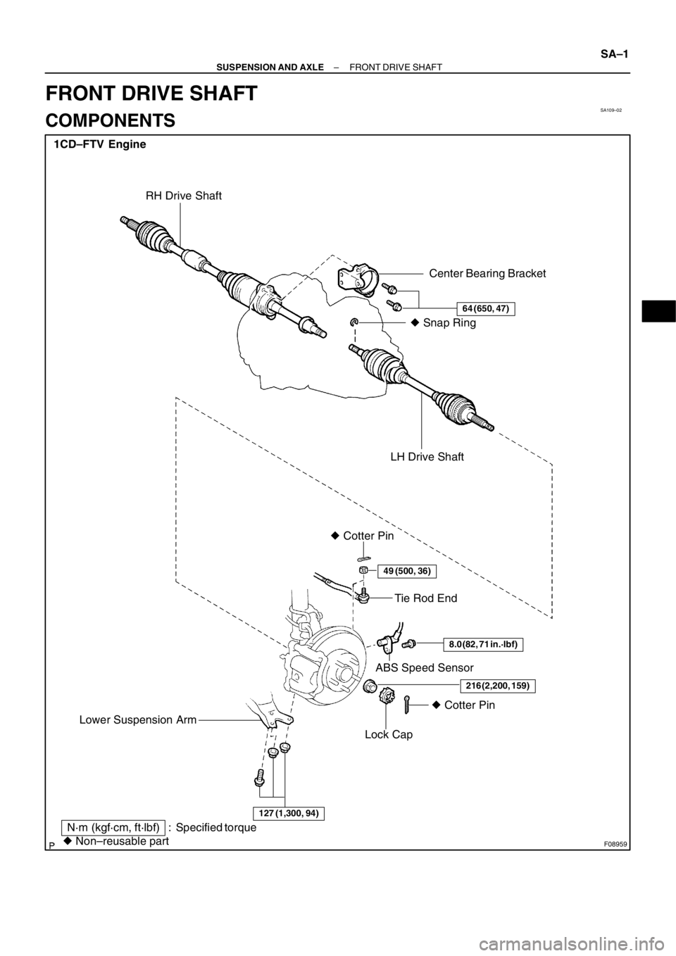
SA109–02
F08959
1CD–FTV Engine
Tie Rod End
ABS Speed Sensor � Cotter Pin
Lock Cap
� Non–reusable part
N·m (kgf·cm, ft·lbf) : Specified torqueLH Drive Shaft� Snap Ring
� Cotter Pin
Center Bearing Bracket
64 (650, 47)
49 (500, 36)
8.0 (82, 71 in.·lbf)
216 (2,200, 159)
RH Drive Shaft
127 (1,300, 94)
Lower Suspension Arm
– SUSPENSION AND AXLEFRONT DRIVE SHAFT
SA–1
FRONT DRIVE SHAFT
COMPONENTS
Page 179 of 349
F08949� Non–reusable part� Dynamic Damper
� Dust Cover � Snap Ring Outboard Joint Shaft
� Boot
� Boot
Tripod
RH Inboard Joint Shaft� Snap Ring
Bearing CaseStraight Pin
Inboard Joint Shaft
� Dust Cover LH� Boot ClampBearing
� Snap Ring 1CD–FTV Engine
� Dynamic Damper Clamp
� Boot Clamp
� Boot Clamp
� Boot Clamp SA–2
– SUSPENSION AND AXLEFRONT DRIVE SHAFT
Page 196 of 349
BR11S–01
F08980
F08981
F08982
New O–Ring
F08970
F08969
– BRAKEVACUUM PUMP (1CD–FTV)
BR–7
REASSEMBLY
1. INSTALL COUPLING
(a) Place the coupling to the rotor shaft.
(b) Install a new snap ring to the rotor shaft.
2. INSTALL ROTOR INTO CASING
Coat the rotor with engine oil, and install it to the rotor shaft.
3. INSTALL 5 BLADES
(a) Coat the 5 blades with engine oil.
(b) Install the 5 blades with the round end facing outward.
HINT:
Be sure that the blades and rotor surfaces are even.
4. INSTALL END COVER
(a) Coat 2 new O–rings with engine oil, and place them to the
casing.
(b) Place the vacuum pump on the vise, as shown in the il-
lustration.
NOTICE:
Do not tighten the vise.
(c) Place the end cover, and temporarily install the 3 bolts.
(d) Using a pin punch and hammer, drive in the 2 straight
pins.
(e) Using soft jaws on the vise, place the vacuum pump in the
vise.
NOTICE:
Do not tighten the vise too tightly.
(f) Tighten the 3 bolts.
Torque: 7.8 N·m (80 kgf·cm, 69 in.·lbf)
Page 198 of 349
BR11T–01
������
������F08964
New O–RingVacuum Hose
Oil Hose
– BRAKEVACUUM PUMP (1CD–FTV)
BR–9
INSTALLATION
1. INSTALL VACUUM PUMP
(a) Coat 2 new O–rings with engine oil, and install them to the
vacuum pump.
(b) Insert the vacuum pump, align the coupling with slit of the
camshaft.
(c) Install the 2 bolts.
Torque: 21 N·m (214 kgf·cm, 15 ft·lbf)
2. CONNECT 2 VACUUM HOSES AND OIL HOSE
Page 201 of 349
 4A–FE and 7A–FE Engines
Vane Pump
Pulley
Crank PulleyA/C
Compressor
Pulley
F03726
98 N (10kgf, 22 lbf) 3S–FE Engine
Vane Pump
Pulley
Crank Pulley
F0")
P06717
SR0I6–02
F01334
98 N (10kgf, 22 lbf) 4A–FE and 7A–FE Engines
Vane Pump
Pulley
Crank PulleyA/C
Compressor
Pulley
F03726
98 N (10kgf, 22 lbf) 3S–FE Engine
Vane Pump
Pulley
Crank Pulley
F01335
2C–T, 2C–TE and 1CD–FTV Engines
Vane Pump Pulley
A/C Compressor
Pulley Crank Pulley 98 N (10 kgf, 22 lbf)
– STEERINGDRIVE BELT
SR–1
DRIVE BELT
INSPECTION
1. INSPECT DRIVE BELT
Visually check the belt for excessive wear, frayed cords, etc.
If any defect has been found, replace the drive belt.
HINT:
Cracks on the rib side of a belt are considered acceptable. If the
missing chunks from the ribs are found on the belt, it should be
replaced.
2. CHECK DRIVE BELT TENSION
Measure the drive belt deflection.
Drive belt tension: at 98 N (10 kgf, 22 lbf)
4A–FE and 7A–FE engines:
New belt5 – 6 mm (0.20 – 0.24 in.)
Used belt6 – 8 mm (0.24 – 0.31 in.)
3S–FE engine:
New belt8 – 10 mm (0.31 – 0.39 in.)
Used belt10 – 13 mm (0.39 – 0.51 in.)
2C–T, 2C–TE and 1CD–FTV engines:
New belt11 – 14 mm (0.43 – 0.55 in.)
Used belt15 – 18 mm (0.59 – 0.71 in.)
Page 202 of 349
P06723
CORRECT WRONGWRONG
Z11352
SR–2
– STEERINGDRIVE BELT
HINT:
�”New belt” refers to a belt which has been used less than
5 minutes on a running engine.
�”Used belt” refers to a belt which has been used on a run-
ning engine for 5 minutes or more.
�After installing a belt, check that it fits properly in the
ribbed grooves.
�Check with your hand to confirm that the belt has not
slipped out of the groove on the bottom of the pulley.
�After installing a new belt, run the engine for about 5 min-
utes and recheck the belt tension.
(Reference)
�Using a belt tension gauge, measure the drive belt ten-
sion.
Drive belt tension:
4A–FE, 7A–FE and 3S–FE engines:
New belt441 – 539 N (45 – 55 kgf)
Used belt245 – 392 N (25 – 40 kgf)
2C–T, 2C–TE and 1CD–FTV engines:
New belt539 – 637 N (55 – 65 kgf)
Used belt245 – 392 N (25 – 40 kgf)
If the belt tension is not as specified, adjust it.
Page 203 of 349
 or less
– STEERINGPOWER STEERING")
F03737
4A–FE and 7A–FE Engines
2C–T, 2C–TE, 3S–FE and 1CD–FTV
EnginesSR0I8–02
R07281
Normal
Abnormal
R10552Engine IdlingEngine Stopped 5 mm (0.20 in.) or less
– STEERINGPOWER STEERING FLUID
SR–3
POWER STEERING FLUID
INSPECTION
1. CHECK FLUID LEVEL
(a) Keep the vehicle level.
(b) With the engine stopped, check the fluid level in the oil
reservoir.
If necessary, add fluid.
Fluid: ATF DEXRON II or III
HINT:
Check that the fluid level is within the HOT LEVEL range on the
reservoir / reservoir cap dipstick.
If the fluid is cold, check that it is within the COLD LEVEL range.
(c) Start the engine and run it at idle.
(d) Turn the steering wheel from lock to lock several times to
boost fluid temperature.
Fluid temperature: 80�C (176�F)
(e) Check for foaming or emulsification.
If there is foaming or emulsification, bleed power steering sys-
tem (See Pub. No. RM599E on page SR–5).
(f) With the engine idling, measure the fluid level in the oil
reservoir.
(g) Stop the engine.
(h) Wait a few minutes and remeasure the fluid level in the oil
reservoir.
Maximum fluid level rise: 5 mm (0.20 in.)
If a problem is found, bleed power steering system (See Pub.
No. RM599E on page SR–5).
(i) Check the fluid level.
Page 204 of 349
F04157
4A–FE and 7A–FE Engines 2C–T, 2C–TE and 1CD–FTV Engines
3S–FE Engine SSTAttachment
Pressure Feed
Tube
IN
OUT
OUT
Attachment
SSTAttachment
Pressure Feed
TubeIN
Attachment
AttachmentSST
OUT IN
SR–4
– STEERINGPOWER STEERING FLUID
2. CHECK STEERING FLUID PRESSURE
(a) Disconnect the pressure feed tube from the PS vane
pump [See Pub. No. RM599E on page SR–21 (4A–FE
and 7A–FE engines), SR–24 (3S–FE engine) and see
page SR–8 (2C–T, 2C–TE and 1CD–FTV engines)].
(b) Connect SST, as shown in the illustration below.
SST 09640–10010 (09641–01010, 09641–01030,
09641–01060)
NOTICE:
Check that the valve of the SST is in the open position.
(c) Bleed the power steering system (See Pub. No. RM599E
on page SR–5).
(d) Start the engine and run it at idle.
(e) Turn the steering wheel from lock to lock several times to
boost fluid temperature.
Fluid temperature: 80�C (176�F)


BR–7
REASSEMBLY
1. INSTALL COUPLING
(a) Place the coupling to the rotor shaft.
(b) Install a new snap ring")