Page 133 of 656

5E2-8 ANTILOCK BRAKE SYSTEM (ABS)
b) Problem Symptom Confirmation
Check if what the customer claimed in “CUSTOMER QUESTIONNAIRE” is actually found in the vehicle
and if that symptom is found, whether it is identified as a failure. (This step should be shared with the cus-
tomer if possible.) Check warning lamps related to brake system referring to “EBD WARNING LAMP
(BRAKE WARNING LAMP) CHECK” and “ABS WARNING LAMP CHECK” in this section.
c) Diagnostic Trouble Code (DTC) Check, Record and Clearance
Perform “DIAGNOSTIC TROUBLE CODE CHECK” procedure in this section, record it and then clear it
referring to “DIAGNOSTIC TROUBLE CODE CLEARANCE” in this section.
If the malfunction DTC which was once displayed and then cleared cannot be detected (indicated) again
when the ignition switch is turned ON, attempt to diagnose the trouble based on the DTC recorded in this
step may mislead the diagnosis or make diagnosing difficult. Proceed to Step 2) to check control module for
proper self-diagnosis function.
If the malfunction DTC which was once displayed and then cleared can be detected (indicated) again when
ignition switch is turned ON, proceed to Step 3).
2) DRIVING TEST
Test drive the vehicle at 40 km/h for more than a minute and check if any trouble symptom (such as abnor-
mal lighting of ABS warning light) exists.
If the malfunction DTC is confirmed again at ignition switch ON, driving test as described in above is not nec-
essary. Proceed to Step 3).
3) DIAGNOSTIC TROUBLE CODE CHECK
Recheck diagnostic trouble code referring to “DTC CHECK” as shown in the following page.
4) DIAGNOSTIC TROUBLE CODE FLOW TABLE
According to Diagnostic flow table for the diagnostic trouble code confirmation in Step 3), locate the cause of
the trouble, namely in a sensor, switch, wire harness, connector, actuator assembly or other part and repair
or replace faulty parts.
5)“DIAGNOSIS” IN “BRAKES” SECTION
Check the parts or system suspected as a possible cause referring to “DIAGNOSIS” in “BRAKES” section
and based on symptoms appearing on the vehicle (symptom obtained through Steps 1)-a, 1)-b and 2) and
repair or replace faulty parts, if any).
6) CHECK FOR INTERMITTENT PROBLEM
Check parts where an intermittent trouble is easy to occur (e.g., wire harness, connector, etc.), referring to
“INTERMITTENT TROUBLE” in “GENERAL INFORMATION” section and related circuit of trouble code
recorded in Step 1)-c.
7) FINAL CONFIRMATION TEST
Confirm that the problem symptom has gone and the ABS is free from any abnormal conditions. If what has
been repaired is related to the malfunction DTC, clear the DTC once and perform test driving and confirm
that no DTC is indicated.
Page 134 of 656
ANTILOCK BRAKE SYSTEM (ABS) 5E2-9
ABS Warning Lamp Check
1) Turn ignition switch ON.
2) Check that ABS warning lamp (1) comes ON for about 2 sec-
onds and then goes off.
If any faulty condition is found, advance to Diagnostic Flow
Table-A, B, C or D.
EBD Warning Lamp (Brake Warning Lamp)
Check
1) Turn ignition switch ON with parking brake applied.
2) Check that EBD warning lamp (brake warning lamp) (1) is
turned ON.
3) Release parking brake with ignition switch ON and check
that EBD warning lamp (brake warning lamp) goes off.
If it doesn’t go off, go to “TABLE-E” in this section.
NOTE:
Perform this check on a level place.
Page 135 of 656
5E2-10 ANTILOCK BRAKE SYSTEM (ABS)
Diagnostic Trouble Code (DTC) Check (Using
ABS Warning Lamp)
1) Perform ABS WARNING LAMP CHECK described above.
2) Using service wire (4), connect diagnosis switch terminal (2)
of monitor coupler (1) to ground (3).
3) Turn ignition switch ON.
4) Read flashing of ABS warning lamp which represents DTC
as shown in example below and write it down. When more
than 2 DTCs are stored in memory, flashing for each DTC is
repeated three times starting with the smallest DTC number
in increasing order.
For details of DTC, refer to “DTC TABLE”.
Example : When right-front wheel speed sensor circuit opens (DTC 21)
5) After completing the check, turn ignition switch off, discon-
nect service wire from monitor coupler.
Page 136 of 656

ANTILOCK BRAKE SYSTEM (ABS) 5E2-11
Diagnostic Trouble Code (DTC) Check (Using
SUZUKI Scan Tool)
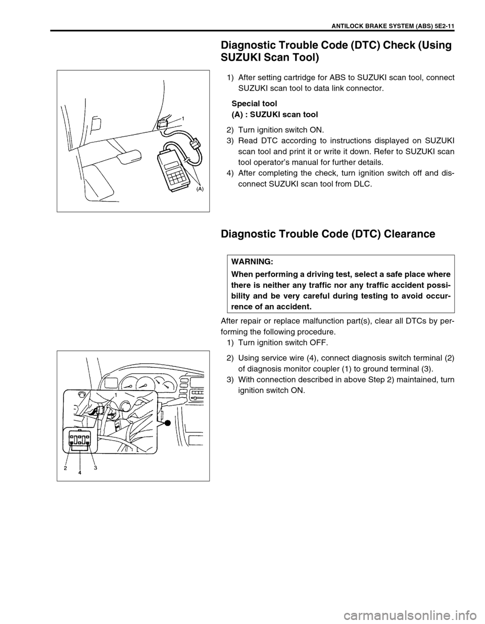
1) After setting cartridge for ABS to SUZUKI scan tool, connect
SUZUKI scan tool to data link connector.
Special tool
(A) : SUZUKI scan tool
2) Turn ignition switch ON.
3) Read DTC according to instructions displayed on SUZUKI
scan tool and print it or write it down. Refer to SUZUKI scan
tool operator’s manual for further details.
4) After completing the check, turn ignition switch off and dis-
connect SUZUKI scan tool from DLC.
Diagnostic Trouble Code (DTC) Clearance
After repair or replace malfunction part(s), clear all DTCs by per-
forming the following procedure.
1) Turn ignition switch OFF.
2) Using service wire (4), connect diagnosis switch terminal (2)
of diagnosis monitor coupler (1) to ground terminal (3).
3) With connection described in above Step 2) maintained, turn
ignition switch ON.
WARNING:
When performing a driving test, select a safe place where
there is neither any traffic nor any traffic accident possi-
bility and be very careful during testing to avoid occur-
rence of an accident.
Page 137 of 656
5E2-12 ANTILOCK BRAKE SYSTEM (ABS)
4) Repeat disconnecting and reconnecting of service wire
between diagnosis and ground terminals 5 times or more at
about 1sec. interval within 10 seconds.
5) Turn ignition switch OFF and disconnect service wire from
monitor coupler.
6) Perform “DRIVING TEST” (Step 2 of “ABS DIAGNOSTIC
FLOW TABLE” in this section) and “DTC CHECK” and con-
firm that normal DTC (DTC 12) is displayed ; not malfunction
DTC.
Diagnostic Trouble Code (DTC) Table
O : Open
S : Short
T : About 10 seconds
NOTE:
It is also possible to clear DTC by using SUZUKI scan
tool. Refer to Cartridge Manual for procedure to clear
DTC.
CAUTION:
Be sure to perform “ABS DIAGNOSTIC FLOW TABLE” before starting diagnosis.
DTC
(displayed
on SUZUKI
scan tool)DTC
(indicated by
ABS warning
lamp)ABS warning lamp flashing
patternDIAGNOSTIC ITEMS
NO DTC 12 Normal
C1015 15 G sensor circuit and 4WD lamp circuit
C1021 21 RF
Wheel speed sensor circuit C1025 25 LF
C1031 31 RR
C1035 35 LR
Page 139 of 656

5E2-14 ANTILOCK BRAKE SYSTEM (ABS)
System Circuit
1. Battery 11. ABS fail-safe transistor (Solenoid valve transistor) 21. To ECM and SDM (if equipped)
2. Main fuses 12. ABS pump motor transistor 22. Stop lamp
3. Ignition switch 13. Pump motor 23. Stop lamp switch
4. Circuit fuses 14. Solenoid valves 24. G sensor (For 4WD vehicle only)
5. Combination meter 15. Diagnosis monitor coupler 25. 4WD lamp (For 4WD vehicle only)
6. ABS warning lamp 16. Right-rear wheel speed sensor 26. ECM (PCM) (For 4WD vehicle only)
7. Brake warning lamp (“EBD” warning lamp) 17. Left-rear wheel speed sensor 27. 4WD switch (For 4WD vehicle only)
8. Warning lamp driver module (for ABS) 18. Right-front wheel speed sensor 28. ECM (PCM)
9. ABS hydraulic unit/control module assembly 19. Left-front wheel speed sensor
10. Terminal arrangement of connector E136 for
ABS hydraulic unit/control module assembly20. Data link connector
TERMINAL CIRCUIT TERMINAL CIRCUIT
E1361 Idle up signal
E13614 ABS warning lamp
2 Stop lamp switch 15 Left-front wheel speed sensor (+)
3 Right-front wheel speed sensor (+) 16 Left-front wheel speed sensor (–)
4 Right-front wheel speed sensor (–) 17 4WD switch
5–18 Ignition switch
6 Right-rear wheel speed sensor (–) 19 Left-rear wheel speed sensor (+)
7 Right-rear wheel speed sensor (+) 20 Left-rear wheel speed sensor (–)
8–21 Data link connector
9–22 Ground (for ABS pump motor)
10 Brake warning lamp (EBD warning lamp) 23 ABS pump motor relay
11 G sensor (For 4WD vehicle only) 24 Ground (for ABS control module)
12 Diagnosis switch terminal 25 ABS fail-safe relay
13 Ground (For G sensor) (For 4WD vehicle only)
Page 140 of 656

ANTILOCK BRAKE SYSTEM (ABS) 5E2-15
Table-A ABS Warning Lamp Circuit Check – Lamp Does Not Come “ON” at
Ignition Switch ON
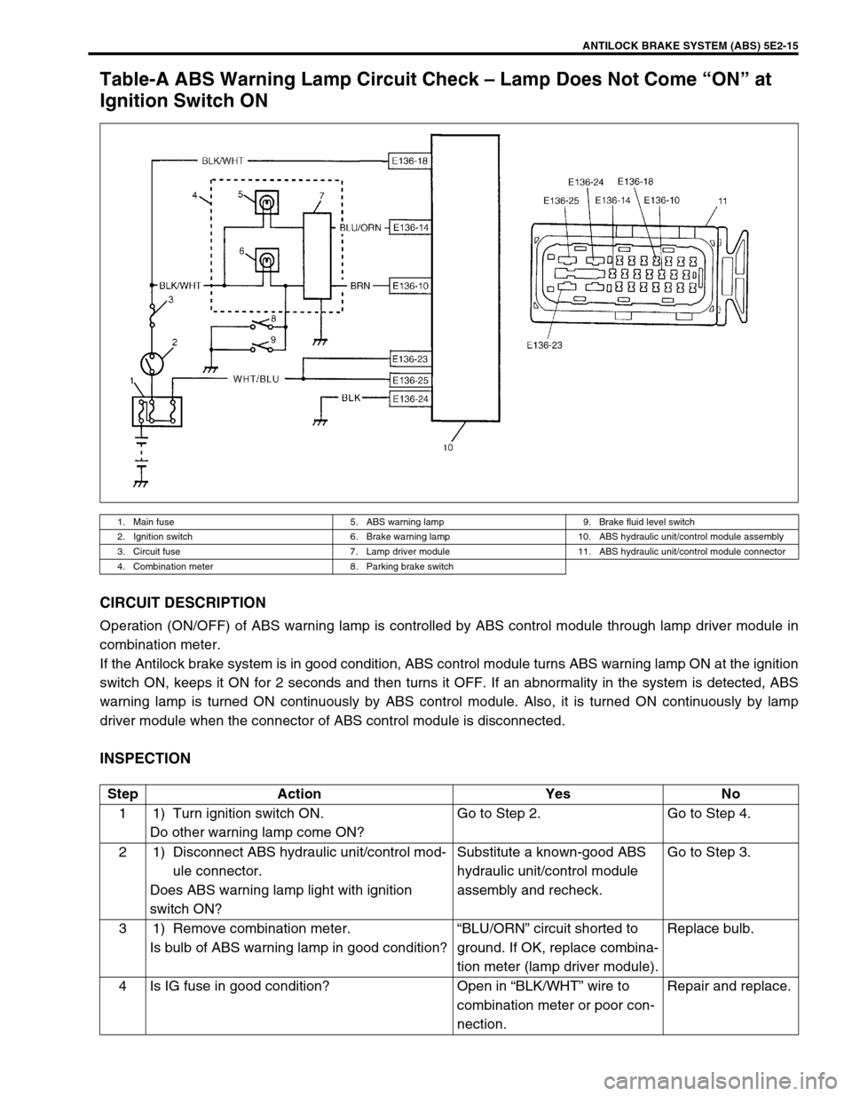
CIRCUIT DESCRIPTION
Operation (ON/OFF) of ABS warning lamp is controlled by ABS control module through lamp driver module in
combination meter.
If the Antilock brake system is in good condition, ABS control module turns ABS warning lamp ON at the ignition
switch ON, keeps it ON for 2 seconds and then turns it OFF. If an abnormality in the system is detected, ABS
warning lamp is turned ON continuously by ABS control module. Also, it is turned ON continuously by lamp
driver module when the connector of ABS control module is disconnected.
INSPECTION
1. Main fuse 5. ABS warning lamp 9. Brake fluid level switch
2. Ignition switch 6. Brake warning lamp 10. ABS hydraulic unit/control module assembly
3. Circuit fuse 7. Lamp driver module 11. ABS hydraulic unit/control module connector
4. Combination meter 8. Parking brake switch
Step Action Yes No
1 1) Turn ignition switch ON.
Do other warning lamp come ON?Go to Step 2. Go to Step 4.
2 1) Disconnect ABS hydraulic unit/control mod-
ule connector.
Does ABS warning lamp light with ignition
switch ON?Substitute a known-good ABS
hydraulic unit/control module
assembly and recheck.Go to Step 3.
3 1) Remove combination meter.
Is bulb of ABS warning lamp in good condition?“BLU/ORN” circuit shorted to
ground. If OK, replace combina-
tion meter (lamp driver module).Replace bulb.
4 Is IG fuse in good condition? Open in “BLK/WHT” wire to
combination meter or poor con-
nection.Repair and replace.
Page 141 of 656

5E2-16 ANTILOCK BRAKE SYSTEM (ABS)
Table-B ABS Warning Lamp Circuit Check – Lamp Comes “ON” Steady
Refer to TABLE – A for System Circuit Diagram and Circuit Description.
INSPECTION
Step Action Yes No
1 Perform diagnostic trouble code check. Is there
any DTC (including code No.12, NO CODES on
SUZUKI scan tool) exists?Go to Step 2. Go to Step 3.
2 Does malfunction DTC (other than code No.12)
exist at Step 1?Go to Step 7 of “ABS
DIAGNOSTIC FLOW
TABLE” in this section.Go to Step 3.
3 1) Disconnect ABS hydraulic unit/control mod-
ule connector.
2) Check for proper connection to ABS
hydraulic unit/control module connector at
terminals “E136-14”, “E136-18” and “E136-
24”.
3) If OK then ignition switch ON and measure
voltage at terminal “E136-18” of connector.
Is it 10 – 14 V?Go to Step 4.“BLK/WHT” circuit open.
4 1) With ABS hydraulic unit/control module con-
nector disconnected, turn ignition switch ON
and light ABS warning lamp.
2) Connect terminal “E136-14” of discon-
nected connector to ground using service
wire.
Does ABS warning lamp turn off?Go to Step 5.“BLU/ORN” circuit open.
If wire and connection are
OK, replace combination
meter (lamp driver mod-
ule).
5 1) Measure resistance from connector terminal
“E136-24” to body ground.
Is continuity indicated?Substitute a known-good
ABS hydraulic unit/con-
trol module assembly and
recheck.“BLK” circuit open.