1999 SUZUKI GRAND VITARA brake switch
[x] Cancel search: brake switchPage 345 of 656

6E2-12 ENGINE AND EMISSION CONTROL SYSTEM (SEQUENTIAL MULTIPORT FUEL INJECTION FOR H27 ENGINE)
Engine and Emission Control Input/Output Table
Diagnosis
Refer to Section 6-1.
Ignition coil with igniter
HO2S heater control
Input
Output Function
Main relay control
Fuel pump control
Injection control
Ignition control
MIL control Idle air control
EVAP purge control
EGR control
A/C control
A/C condensor fan
controlMain relay
Fuel pump relay
Injectors
MIL
EVAP canister purge
valve IAC valve
EGR valve (if equipped)
HO2S (if equipped)
A/C amplifier
(if equipped)
A/C condensor fan
relay (if equipped)
CMP sensor
MAF sensor
TP sensor
ECT sensor
IAT sensor
HO2S (sensor 1)(if equipped)
VSS
Blower fan switch
Rear defogger switch
PSP switch
Ignition switch
Starter switch
A/C amplifier (if equipped)
TR switch (A/T VEHICLE)
Light switch
Knock sensor
CO adjusting resistor (if equipped)
Test swich terminal (Vehicle with monitor connector)
Diag. swich terminal (Vehicle with monitor connector)
Brake switch (A/T VEHICLE)
ABS control module
Page 348 of 656

ENGINE AND EMISSION CONTROL SYSTEM (SEQUENTIAL MULTIPORT FUEL INJECTION FOR H27 ENGINE) 6E2-15
Idle Speed/Idle Air Control (IAC) Duty Inspec-
tion
Before idle speed/IAC duty check, make sure of the following.
•Lead wires and hoses of engine/emission control systems
are connected securely.
•Accelerator cable is adjusted.
•Ignition timing is within specification.
•All accessories (wipers, heater, lights, A/C, etc.) are out of
service.
•Air cleaner has been properly installed and is in good condi-
tion.
•ECM (PCM) does not detect any malfunction DTC.
After above items are all confirmed, check idle speed and IAC
duty as follows.
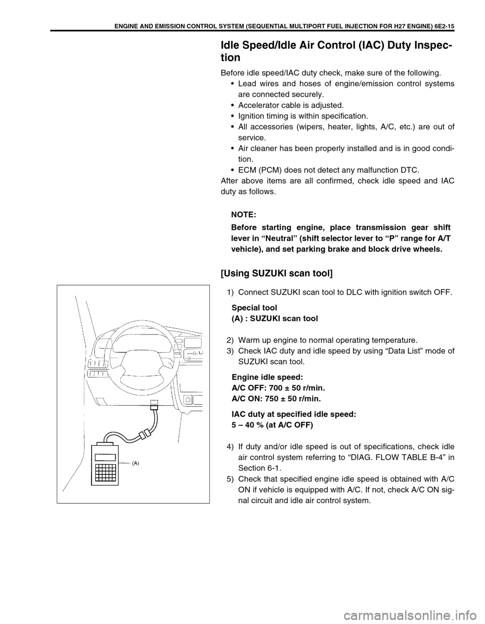
[Using SUZUKI scan tool]
1) Connect SUZUKI scan tool to DLC with ignition switch OFF.
Special tool
(A) : SUZUKI scan tool
2) Warm up engine to normal operating temperature.
3) Check IAC duty and idle speed by using “Data List” mode of
SUZUKI scan tool.
Engine idle speed:
A/C OFF: 700 ± 50 r/min.
A/C ON: 750 ± 50 r/min.
IAC duty at specified idle speed:
5 – 40 % (at A/C OFF)
4) If duty and/or idle speed is out of specifications, check idle
air control system referring to “DIAG. FLOW TABLE B-4” in
Section 6-1.
5) Check that specified engine idle speed is obtained with A/C
ON if vehicle is equipped with A/C. If not, check A/C ON sig-
nal circuit and idle air control system. NOTE:
Before starting engine, place transmission gear shift
lever in “Neutral” (shift selector lever to “P” range for A/T
vehicle), and set parking brake and block drive wheels.
Page 372 of 656

ENGINE AND EMISSION CONTROL SYSTEM (SEQUENTIAL MULTIPORT FUEL INJECTION FOR H27 ENGINE) 6E2-39
HEATER INSPECTION
Refer to “HEATED OXYGEN SENSOR (SENSOR 1) HEATER
INSPECTION”
Vehicle speed sensor (VSS)
ON-VEHICLE INSPECTION
1) Hoist vehicle.
2) Release parking brake lever, set transmission in neutral and
transfer in “2H”.
3) Remove ECM (PCM) cover.
4) Connector voltmeter between VSS terminal C51-3-1 of ECM
(PCM) connector and body ground.
5) Turn ignition switch ON and turn rear right tire slowly with
rear left tire locked.
Voltmeter should indicate deflection between 0 – 1 V and 8 –
14 V a few times while tire (1) is turned one revolution.
If check result is not satisfactory, proceed to flow table of
“DTC P0500” in Section 6-1.
REMOVAL, INSPECTION AND INSTALLATION
Refer to “VSS Removal, Inspection or Installation” in Section 7D.
Manifold absolute pressure sensor
REMOVAL
1) Disconnect negative (–) cable at battery.
2) Disconnect connector from manifold absolute pressure sen-
sor.
3) Remove manifold absolute pressure sensor from intake
manifold.
[A]: Terminal arrangement of ECM (PCM) coupler
(viewed from harness side)
1. VSS
Page 389 of 656

6F2-6 IGNITION SYSTEM (FOR H27 ENGINE)
Ignition Spark Check
1) Remove surge tank cover.
2) Disconnect injector coupler (1).
3) Remove spark plug and check it for condition and type, refer-
ring to “SPARK PLUG” in this section.
4) If OK, connect ignition coil coupler to ignition coil assembly
and connect spark plug to ignition coil assembly. Ground
spark plug.
5) Crank engine and check if each spark plug sparks.
If no spark is emitted, inspect the related parts as described
under “DIAGNOSIS” in this section.
6) After checking, install spark plug, referring to “SPARK PLUG”
in this section.
7) Connect injector coupler (1).
8) Install surge tank cover.
Ignition Timing Check and Adjustment
1) Start engine and warm it up to normal operating tempera-
ture.
2) Make sure that all of electrical loads except ignition are
switched off.
3) Check to be sure that idle speed is within specification.
Refer to Section 6E2.
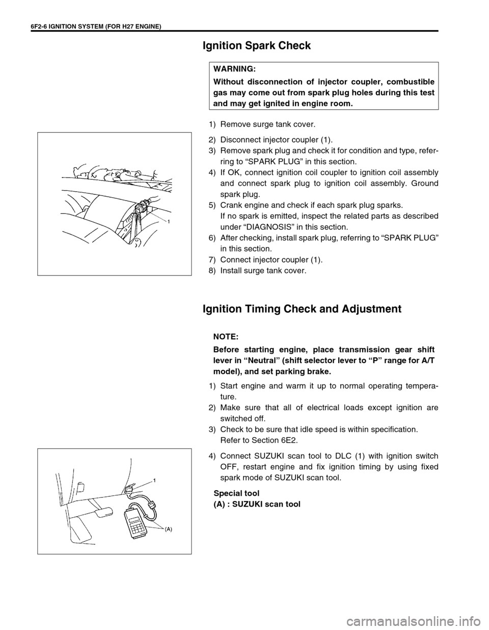
4) Connect SUZUKI scan tool to DLC (1) with ignition switch
OFF, restart engine and fix ignition timing by using fixed
spark mode of SUZUKI scan tool.
Special tool
(A) : SUZUKI scan tool WARNING:
Without disconnection of injector coupler, combustible
gas may come out from spark plug holes during this test
and may get ignited in engine room.
NOTE:
Before starting engine, place transmission gear shift
lever in “Neutral” (shift selector lever to “P” range for A/T
model), and set parking brake.
Page 424 of 656

AUTOMATIC TRANSMISSION (4 A/T) 7B1-15
Trouble Diagnosis Table 1
Trouble Diagnosis Table 2
TRANSMISSION FLUID
RUNNING CONDITION
4 Perform stall test, time rag test, line pressure test,
engine brake test and “P” range test referring to
“STALL TEST”, “LINE PRESSURE TEST”, “ENGINE
BRAKE TEST” and ““P” RANGE TEST” in this section.
Are the test results satisfactory?Go to Step 5. Proceed to “TROUBLE
DIAGNOSIS TABLE 3” in
this section.
5 Proceed to “TROUBLE DIAGNOSIS TABLE 2” in this
section.
Is trouble identified?Repair or replace
defective parts.Proceed to “TROUBLE
DIAGNOSIS TABLE 3” in
this section. Step Action Yes No
Condition Possible Cause Correction
TCC does not operateBrake pedal (stop lamp) switch or its circuit
faulty (H25 engine only)Refer to “DIAGNOSTIC FLOW
TABLE A-1” in this section.
4WD low switch or its circuit faulty
Engine coolant temp. sensor or its circuit faulty
Cruise control signal circuit faulty (if equipped)
Gear does not change
to 4thO/D off switch or its circuit faulty Refer to “DIAGNOSTIC FLOW
TABLE A-2” in this section.
4WD low switch or its circuit faulty
Engine coolant temp. sensor or its circuit faulty
Cruise control signal circuit faulty (if equipped)
Condition Possible Cause Correction
Low fluid pressureClogged oil pump strainer Wash strainer.
Malfunction of pressure regulator valve Overhaul valve body.
High fluid pressurePressure regulator valve Overhaul valve body.
Condition Possible Cause Correction
Unable to run in all
rangeRegulator valve stick Replace.
Clogged oil strainer Wash strainer.
Seized or broken planetary gear Repair or replace.
Faulty manual valve Replace.
Poor 1st speed run-
ning or excessive slip-
page in “D” or “2”Faulty 1–2 shift valve Replace.
Page 427 of 656

7B1-18 AUTOMATIC TRANSMISSION (4 A/T)
Table A-1 : No TCC Lock-Up Occurs
SYSTEM DESCRIPTION
PCM turns TCC solenoid OFF under any of the following conditions.
•Brake pedal switch : ON
•4WD LOW switch : ON
•Cruise control module : TCC OFF command signal is output (if equipped).
•ECT : ECT < 30 °C (86 °F)
TROUBLESHOOTING
WARNING:
When performing a road test, select a place where there is no traffic or possibility of a traffic acci-
dent and very careful during testing to avoid occurrence of an accident.
Road test should be carried out with 2 person, a driver and tester, on a level road.
Step Action Yes No
1Was “AUTOMATIC TRANSMISSION DIAG-
NOSTIC FLOW TABLE” performed?Go to Step 2. Go to “AUTOMATIC
TRANSMISSION DIAG-
NOSTIC FLOW TABLE” in
this section.
2 ECT check :
1) Warm up engine to normal operating tem-
perature.
2) Check ECT using scan tool.
Is ECT more than 30 °C (86 °F)?Go to Step 3. Faulty ECT sensor, its cir-
cuit or engine cooling sys-
tem.
If OK, substitute a known-
good PCM and recheck.
3 Perform running test under the following condi-
tions and check voltage between C51-1-8 termi-
nal of PCM coupler and ground.
•Normal mode in “D” range.
•Transfer “2H” position.
•Cruise control is not operated (if equipped).
•Brake pedal released.
•Drive vehicle with TCC ON condition refer-
ring to “TCC LOCK-UP DIAGRAM” in this
section.
Is it battery voltage?Faulty TCC solenoid
valve, its circuit or trans-
mission.Go to Step 4.
4 Brake switch signal inspection :
With ignition switch ON, check voltage between
E61-34 terminal of PCM coupler terminal and
ground.
Brake switch specification
Brake pedal released : 0 V
Brake pedal depressed : Battery voltage
Is the result as specified?Go to Step 5. Faulty brake pedal switch
or its circuit.
If OK, substitute a known-
good PCM and recheck.
Page 450 of 656

AUTOMATIC TRANSMISSION (4 A/T) 7B1-41
Manual Road Test
This test check the gear being used in “L”, “2” or “D” range when
driven with unoperated gear shift control system. Test drive vehi-
cle on a level road.
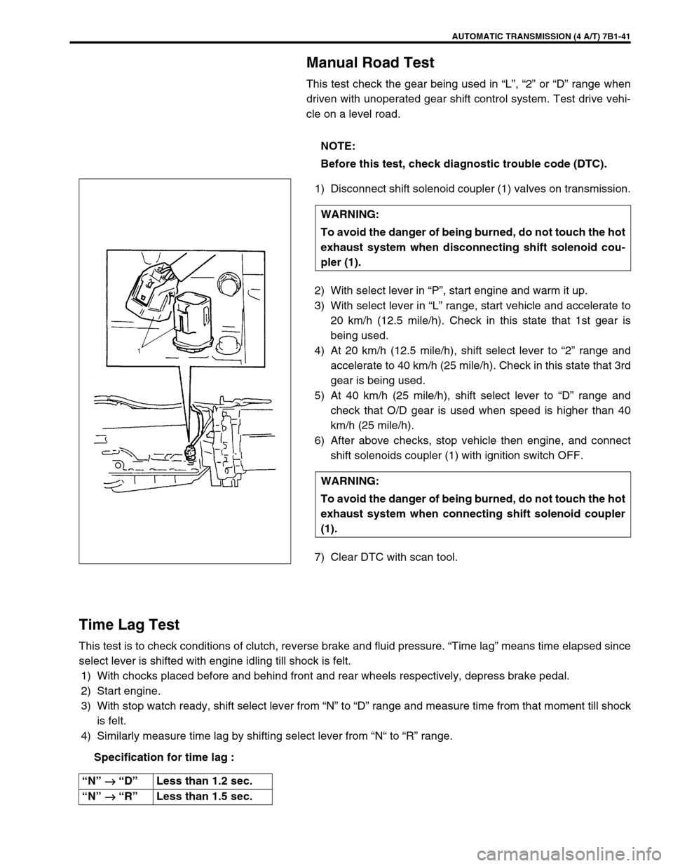
1) Disconnect shift solenoid coupler (1) valves on transmission.
2) With select lever in “P”, start engine and warm it up.
3) With select lever in “L” range, start vehicle and accelerate to
20 km/h (12.5 mile/h). Check in this state that 1st gear is
being used.
4) At 20 km/h (12.5 mile/h), shift select lever to “2” range and
accelerate to 40 km/h (25 mile/h). Check in this state that 3rd
gear is being used.
5) At 40 km/h (25 mile/h), shift select lever to “D” range and
check that O/D gear is used when speed is higher than 40
km/h (25 mile/h).
6) After above checks, stop vehicle then engine, and connect
shift solenoids coupler (1) with ignition switch OFF.
7) Clear DTC with scan tool.
Time Lag Test
This test is to check conditions of clutch, reverse brake and fluid pressure. “Time lag” means time elapsed since
select lever is shifted with engine idling till shock is felt.
1) With chocks placed before and behind front and rear wheels respectively, depress brake pedal.
2) Start engine.
3) With stop watch ready, shift select lever from “N” to “D” range and measure time from that moment till shock
is felt.
4) Similarly measure time lag by shifting select lever from “N“ to “R” range.
Specification for time lag :NOTE:
Before this test, check diagnostic trouble code (DTC).
WARNING:
To avoid the danger of being burned, do not touch the hot
exhaust system when disconnecting shift solenoid cou-
pler (1).
WARNING:
To avoid the danger of being burned, do not touch the hot
exhaust system when connecting shift solenoid coupler
(1).
“N” →
→→ → “D”Less than 1.2 sec.
“N” →
→→ → “R”Less than 1.5 sec.
Page 455 of 656

7B1-46 AUTOMATIC TRANSMISSION (4 A/T)
MANUAL SELECTOR ASSEMBLY
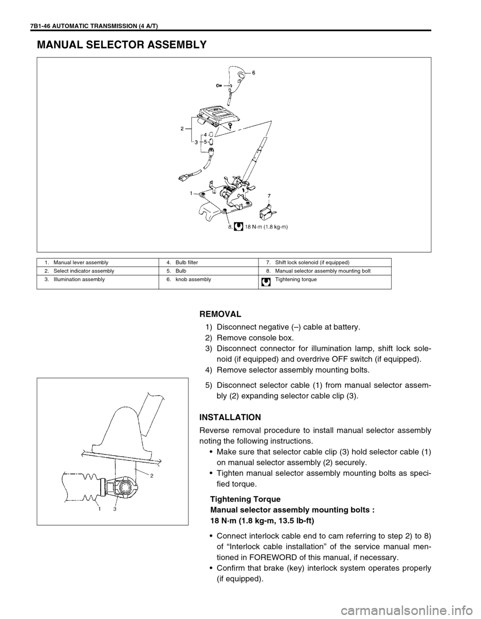
REMOVAL
1) Disconnect negative (–) cable at battery.
2) Remove console box.
3) Disconnect connector for illumination lamp, shift lock sole-
noid (if equipped) and overdrive OFF switch (if equipped).
4) Remove selector assembly mounting bolts.
5) Disconnect selector cable (1) from manual selector assem-
bly (2) expanding selector cable clip (3).
INSTALLATION
Reverse removal procedure to install manual selector assembly
noting the following instructions.
•Make sure that selector cable clip (3) hold selector cable (1)
on manual selector assembly (2) securely.
•Tighten manual selector assembly mounting bolts as speci-
fied torque.
Tightening Torque
Manual selector assembly mounting bolts :
18 N·m (1.8 kg-m, 13.5 lb-ft)
•Connect interlock cable end to cam referring to step 2) to 8)
of “Interlock cable installation” of the service manual men-
tioned in FOREWORD of this manual, if necessary.
•Confirm that brake (key) interlock system operates properly
(if equipped).
1. Manual lever assembly 4. Bulb filter 7. Shift lock solenoid (if equipped)
2. Select indicator assembly 5. Bulb 8. Manual selector assembly mounting bolt
3. Illumination assembly 6. knob assembly Tightening torque