1999 SUZUKI GRAND VITARA brake switch
[x] Cancel search: brake switchPage 106 of 656
BRAKES 5-1
5
SECTION 5
BRAKES
CONTENTS
Diagnosis .......................................................... 5-2
Diagnosis Table ............................................. 5-2
WARNING:
For vehicles equipped with Supplemental Restraint (Air Bag) System:
Service on and around the air bag system components or wiring must be performed only by an
authorized SUZUKI dealer. Refer to “Air Bag System Components and Wiring Location View” under
“General Description” in air bag system section in order to confirm whether you are performing ser-
vice on or near the air bag system components or wiring. Please observe all WARNINGS and “Ser-
vice Precautions” under “On-Vehicle Service” in air bag system section before performing service
on or around the air bag system components or wiring. Failure to follow WARNINGS could result in
unintentional activation of the system or could render the system inoperative. Either of these two
conditions may result in severe injury.
Technical service work must be started at least 90 seconds after the ignition switch is turned to the
“LOCK” position and the negative cable is disconnected from the battery. Otherwise, the system
may be activated by reserve energy in the Sensing and Diagnostic Module (SDM).
NOTE:
For the description (items) not found in this section refer to the same section of the Service Manual
mentioned in the FOREWORD of this manual.
When inspecting and servicing vehicle equipped with ABS, be sure to refer to section 5E2 first.
All brake fasteners are important attaching parts in that they could affect the performance of vital
parts and systems, and/or could result in major repair expense. They must be replaced with one of
same part number or with an equivalent part if replacement becomes necessary. Do not use a
replacement part of lesser quality or substitute design. Torque values must be used as specified
during reassembly to assure proper retention of all parts. There is to be no welding as it may result
in extensive damage and weakening of the metal.
Page 107 of 656
5-2 BRAKES
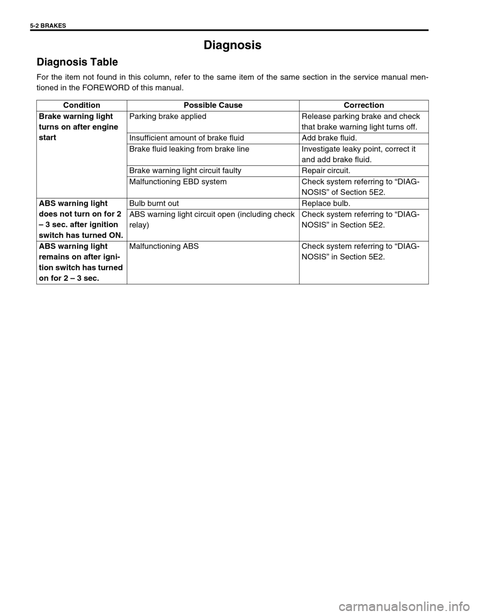
Diagnosis
Diagnosis Table
For the item not found in this column, refer to the same item of the same section in the service manual men-
tioned in the FOREWORD of this manual.
Condition Possible Cause Correction
Brake warning light
turns on after engine
startParking brake applied Release parking brake and check
that brake warning light turns off.
Insufficient amount of brake fluid Add brake fluid.
Brake fluid leaking from brake line Investigate leaky point, correct it
and add brake fluid.
Brake warning light circuit faulty Repair circuit.
Malfunctioning EBD system Check system referring to “DIAG-
NOSIS” of Section 5E2.
ABS warning light
does not turn on for 2
– 3 sec. after ignition
switch has turned ON.Bulb burnt out Replace bulb.
ABS warning light circuit open (including check
relay)Check system referring to “DIAG-
NOSIS” in Section 5E2.
ABS warning light
remains on after igni-
tion switch has turned
on for 2 – 3 sec.Malfunctioning ABS Check system referring to “DIAG-
NOSIS” in Section 5E2.
Page 108 of 656
BRAKES PIPE/HOSE/MASTER CYLINDER 5A-1
5A
SECTION 5A
BRAKES PIPE/HOSE/MASTER CYLINDER
CONTENTS
General Description ....................................... 5A-2
Master Cylinder Assembly............................ 5A-2
On-Vehicle Service......................................... 5A-3
Front Brake Hose/Pipe ................................. 5A-3
Master Cylinder Reservoir ............................ 5A-6Master Cylinder Assembly ........................... 5A-7
Brake Booster .............................................. 5A-8
Tightening Torque Specification ................ 5A-10
Special Tool .................................................. 5A-10
WARNING:
For vehicles equipped with Supplemental Restraint (Air Bag) System:
Service on and around the air bag system components or wiring must be performed only by an
authorized SUZUKI dealer. Refer to “Air Bag System Components and Wiring Location View” under
“General Description” in air bag system section in order to confirm whether you are performing ser-
vice on or near the air bag system components or wiring. Please observe all WARNINGS and “Ser-
vice Precautions” under “On-Vehicle Service” in air bag system section before performing service
on or around the air bag system components or wiring. Failure to follow WARNINGS could result in
unintentional activation of the system or could render the system inoperative. Either of these two
conditions may result in severe injury.
Technical service work must be started at least 90 seconds after the ignition switch is turned to the
“LOCK” position and the negative cable is disconnected from the battery. Otherwise, the system
may be activated by reserve energy in the Sensing and Diagnostic Module (SDM).
NOTE:
For the descriptions (items) not found in this section, refer to the same section of the Service Man-
ual mentioned in the FOREWORD of this manual.
All brake fasteners are important attaching parts in that they could affect the performance of vital
parts and systems, and/or could result in major repair expense. They must be replaced with one of
same part number or with an equivalent part if replacement becomes necessary. Do not use a
replacement part of lesser quality or substitute design. Torque values must be used as specified
during reassembly to assure proper retention of all parts. There is to be no welding as it may result
in extensive damage and weakening of the metal.
Page 118 of 656
PARKING AND REAR BRAKE 5C-1
5C
SECTION 5C
PARKING AND REAR BRAKE
CONTENTS
General Description ....................................... 5C-2
Drum Brake Assembly ................................. 5C-2
On-Vehicle Service......................................... 5C-3
Parking Brake Cable .................................... 5C-3Brake Drum .................................................. 5C-3
Wheel Cylinder............................................. 5C-5
Brake Back Plate ......................................... 5C-5
Tightening Torque Specification .................. 5C-7
WARNING:
For vehicles equipped with Supplemental Restraint (Air Bag) System:
Service on and around the air bag system components or wiring must be performed only by an
authorized SUZUKI dealer. Refer to “Air Bag System Components and Wiring Location View” under
“General Description” in air bag system section in order to confirm whether you are performing ser-
vice on or near the air bag system components or wiring. Please observe all WARNINGS and “Ser-
vice Precautions” under “On-Vehicle Service” in air bag system section before performing service
on or around the air bag system components or wiring. Failure to follow WARNINGS could result in
unintentional activation of the system or could render the system inoperative. Either of these two
conditions may result in severe injury.
Technical service work must be started at least 90 seconds after the ignition switch is turned to the
“LOCK” position and the negative cable is disconnected from the battery. Otherwise, the system
may be activated by reserve energy in the Sensing and Diagnostic Module (SDM).
NOTE:
For the descriptions (items) not found in this section, refer to the same section of the Service Man-
ual mentioned in the FOREWORD of this manual.
All brake fasteners are important attaching parts in that they could affect the performance of vital
parts and systems, and/or could result in major repair expense. They must be replaced with one of
same part number or with an equivalent part if replacement becomes necessary. Do not use a
replacement part of lesser quality or substitute design. Torque values must be used as specified
during reassembly to assure proper retention of all parts. There is to be no welding as it may result
in extensive damage and weakening of the metal.
Page 120 of 656

PARKING AND REAR BRAKE 5C-3
On-Vehicle Service
Parking Brake CableBrake Drum
INSPECTION
Brake drum
Inspect drum for cleanliness. Check wear of its braking surface by
measuring its inside diameter.
Whenever brake drums are removed, they should be thoroughly
cleaned and inspected for cracks, scores, deep grooves.Brake dram inside diameter “a ”
S ta n dard : 2 54 mm (9.99 in .)
S erv ic e L im it : 2 56 m m ( 10.07 i n.)
1. Parking brake switch 6. Equalizer 11. Color ring 16. Crossmember 21. Parking brake cable nut
2. Parking brake lever 7. Pin 12. Cable 17. Chassis frame Tightening torque
3. Parking brake lever bolt 8. Equalizer 13. Grommet 18. Hanger
4. Floor 9. Adjust rod 14. Bolt 19. Rear axle
5. Locking nut 10. Coupler 15. Clamp (if equipped) 20. G-sensor (if equipped)
Page 126 of 656

ANTILOCK BRAKE SYSTEM (ABS) 5E2-1
5E2
SECTION 5E2
ANTILOCK BRAKE SYSTEM (ABS)
CONTENTS
General Description ..................................... 5E2-3
Components/Parts Location ....................... 5E2-3
ABS Hydraulic Unit/control Module
Assembly .................................................... 5E2-4
Self-diagnosis function ........................... 5E2-4
Fail-safe function .................................... 5E2-5
Diagnosis ...................................................... 5E2-5
Precautions in Diagnosing Troubles .......... 5E2-5
ABS Diagnostic Flow Table ........................ 5E2-6
ABS Warning Lamp Check ........................ 5E2-9
EBD Warning Lamp (Brake Warning Lamp)
Check ......................................................... 5E2-9
Diagnostic Trouble Code (DTC) Check
(Using ABS Warning Lamp) ..................... 5E2-10
Diagnostic Trouble Code (DTC) Check
(Using SUZUKI Scan Tool) ...................... 5E2-11
Diagnostic Trouble Code (DTC)
Clearance ................................................. 5E2-11
Diagnostic Trouble Code (DTC) Table ..... 5E2-12
System Circuit .......................................... 5E2-14Table-A ABS Warning Lamp Circuit Check
– Lamp Does Not Come “ON” at Ignition
Switch ON ................................................ 5E2-15
Table-B ABS Warning Lamp Circuit Check
– Lamp Comes “ON” Steady.................... 5E2-16
Table-C ABS Warning Lamp Circuit Check
– The Lamp Flashes Continuously While
Ignition Switch Is ON ................................ 5E2-17
Table-D Code (DTC) Is Not Outputted
Even with Diagnosis Switch Terminal
Connected to Ground............................... 5E2-18
Table-E EBD Warning Lamp (Brake
Warning Lamp) Check – Lamp Comes
“ON” Steady ............................................. 5E2-19
DTC C1015 (DTC 15) – G Sensor Circuit
and 4WD Lamp Circuit ............................. 5E2-20
DTC C1021 (DTC 21), DTC C1022
(DTC 22) – Right-Front Wheel Speed
Sensor Circuit or Sensor Ring ................. 5E2-22
DTC C1025 (DTC 25), DTC C1026
(DTC 26) – Left-Front Wheel Speed WARNING:
For vehicles equipped with Supplemental Restraint (Air Bag) System:
Service on and around the air bag system components or wiring must be performed only by an
authorized SUZUKI dealer. Refer to “Air Bag System Components and Wiring Location View” under
“General Description” in air bag system section in order to confirm whether you are performing ser-
vice on or near the air bag system components or wiring. Please observe all WARNINGS and “Ser-
vice Precautions” under “On-Vehicle Service” in air bag system section before performing service
on or around the air bag system components or wiring. Failure to follow WARNINGS could result in
unintentional activation of the system or could render the system inoperative. Either of these two
conditions may result in severe injury.
Technical service work must be started at least 90 seconds after the ignition switch is turned to the
“LOCK” position and the negative cable is disconnected from the battery. Otherwise, the system
may be activated by reserve energy in the Sensing and Diagnostic Module (SDM).
NOTE:
For the descriptions (items) not found in this section, refer to Section 5E1 of the Service Manual
mentioned in the FOREWORD of this manual.
All brake fasteners are important attaching parts in that they could affect the performance of vital
parts and systems, and/or could result in major repair expense. They must be replaced with one of
same part number or with an equivalent part if replacement becomes necessary. Do not use a
replacement part of lesser quality or substitute design. Torque values must be used as specified
during reassembly to assure proper retention of all parts. There is to be no welding as it may result
in extensive damage and weakening of the metal.
Page 128 of 656

ANTILOCK BRAKE SYSTEM (ABS) 5E2-3
General Description
Components/Parts Location
The ABS (Antilock Brake System) controls the fluid pressure applied to the wheel cylinder of each brake from
the master cylinder so that each wheel is not locked even when hard braking is applied.
This ABS has also the following function.
While braking is applied, but before ABS control becomes effective, braking force is distributed between the
front and rear so as to prevent the rear wheels from being locked too early for better stability of the vehicle.The
main component parts of this ABS include the following parts in addition to those of the conventional brake sys-
tem.
Wheel speed sensor which senses revolution speed of each wheel and outputs its signal.
ABS warning lamp which lights to inform abnormality when system fails to operate properly.
ABS hydraulic unit/control module assembly is incorporated ABS control module, ABS hydraulic unit (actua-
tor assembly), fail-safe relay and pump motor relay.
–ABS control module which sends operation signal to ABS hydraulic unit to control fluid pressure applied to
each wheel cylinder based on signal from each wheel speed sensor so as to prevent wheel from locking.
–ABS hydraulic unit which operates according to signal from ABS control module to control fluid pressure
applied to wheel cylinder of each 4 wheels.
–Fail-safe relay (solenoid valve) relay which supplies power to solenoid valve in ABS hydraulic unit and
pump motor relay.
–Pump motor relay which supplies power to pump motor in ABS hydraulic unit.
G sensor which detects body deceleration speed. (For 4WD model only)
This ABS is equipped with Electronic Brake force Distribution (EBD) system that controls a fluid pressure of rear
wheels to best condition, which is the same function as that of proportioning valve, by the signal from wheel sen-
sor independently of change of load due to load capacity and so on. And if the EBD system fails to operate prop-
erly, the brake warning lamp lights to inform abnormality.
1. Wheel speed sensor (Right-front) 6. Wheel speed sensor (Left-rear) 11. G sensor (For 4WD model only)
2. Stop lamp switch 7. Ground 12. Wheel speed sensor rotor (ring)
3. Data link connector 8. Diagnosis connector (Black connector) 13. 4WD switch (For 4WD model only)
4.“ABS” warning lamp 9. Wheel speed sensor (Left-front) 14. EBD warning lamp (Brake warning lamp)
5. Wheel speed sensor (Right-rear) 10. ABS hydraulic unit/control module assembly
(with ABS pump motor relay and fail-safe relay)
NOTE:
Above figure shows left-hand steering vehicle.
For right-hand steering vehicle, parts with (*) are installed at the side of symmetry.
Page 129 of 656
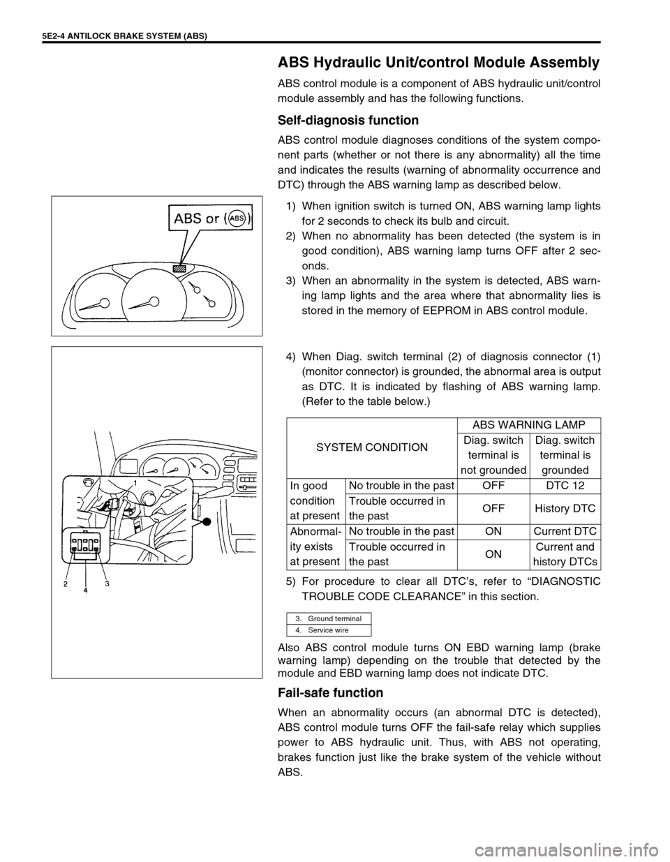
5E2-4 ANTILOCK BRAKE SYSTEM (ABS)
ABS Hydraulic Unit/control Module Assembly
ABS control module is a component of ABS hydraulic unit/control
module assembly and has the following functions.
Self-diagnosis function
ABS control module diagnoses conditions of the system compo-
nent parts (whether or not there is any abnormality) all the time
and indicates the results (warning of abnormality occurrence and
DTC) through the ABS warning lamp as described below.
1) When ignition switch is turned ON, ABS warning lamp lights
for 2 seconds to check its bulb and circuit.
2) When no abnormality has been detected (the system is in
good condition), ABS warning lamp turns OFF after 2 sec-
onds.
3) When an abnormality in the system is detected, ABS warn-
ing lamp lights and the area where that abnormality lies is
stored in the memory of EEPROM in ABS control module.
4) When Diag. switch terminal (2) of diagnosis connector (1)
(monitor connector) is grounded, the abnormal area is output
as DTC. It is indicated by flashing of ABS warning lamp.
(Refer to the table below.)
5) For procedure to clear all DTC’s, refer to “DIAGNOSTIC
TROUBLE CODE CLEARANCE” in this section.
Also ABS control module turns ON EBD warning lamp (brake
warning lamp) depending on the trouble that detected by the
module and EBD warning lamp does not indicate DTC.
Fail-safe function
When an abnormality occurs (an abnormal DTC is detected),
ABS control module turns OFF the fail-safe relay which supplies
power to ABS hydraulic unit. Thus, with ABS not operating,
brakes function just like the brake system of the vehicle without
ABS.
SYSTEM CONDITIONABS WARNING LAMP
Diag. switch
terminal is
not groundedDiag. switch
terminal is
grounded
In good
condition
at presentNo trouble in the past OFF DTC 12
Trouble occurred in
the pastOFF History DTC
Abnormal-
ity exists
at presentNo trouble in the past ON Current DTC
Trouble occurred in
the pastONCurrent and
history DTCs
3. Ground terminal
4. Service wire