1999 SUZUKI GRAND VITARA brake switch
[x] Cancel search: brake switchPage 150 of 656
ANTILOCK BRAKE SYSTEM (ABS) 5E2-25
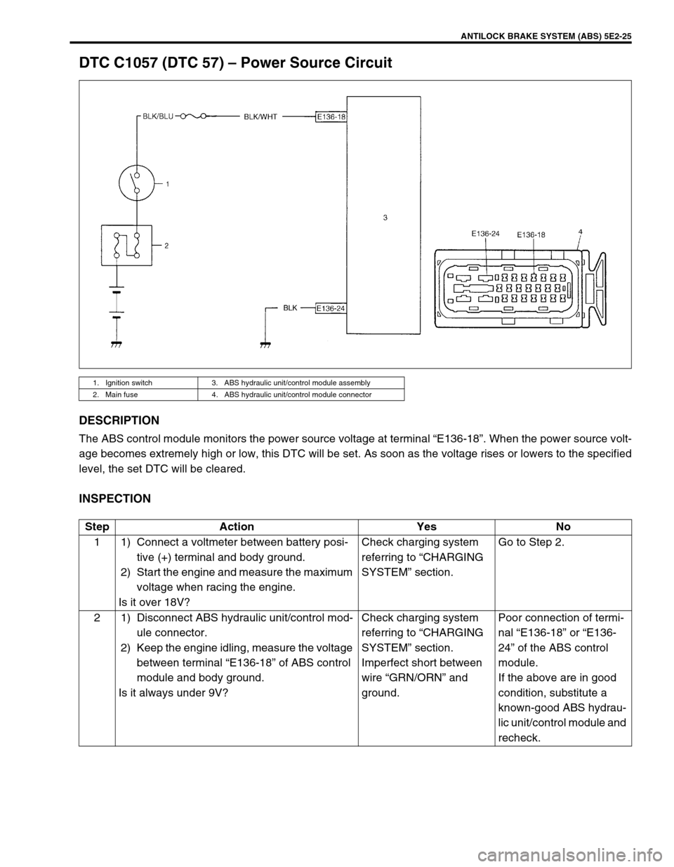
DTC C1057 (DTC 57) – Power Source Circuit
DESCRIPTION
The ABS control module monitors the power source voltage at terminal “E136-18”. When the power source volt-
age becomes extremely high or low, this DTC will be set. As soon as the voltage rises or lowers to the specified
level, the set DTC will be cleared.
INSPECTION
1. Ignition switch 3. ABS hydraulic unit/control module assembly
2. Main fuse 4. ABS hydraulic unit/control module connector
Step Action Yes No
1 1) Connect a voltmeter between battery posi-
tive (+) terminal and body ground.
2) Start the engine and measure the maximum
voltage when racing the engine.
Is it over 18V?Check charging system
referring to “CHARGING
SYSTEM” section.Go to Step 2.
2 1) Disconnect ABS hydraulic unit/control mod-
ule connector.
2) Keep the engine idling, measure the voltage
between terminal “E136-18” of ABS control
module and body ground.
Is it always under 9V?Check charging system
referring to “CHARGING
SYSTEM” section.
Imperfect short between
wire “GRN/ORN” and
ground.Poor connection of termi-
nal “E136-18” or “E136-
24” of the ABS control
module.
If the above are in good
condition, substitute a
known-good ABS hydrau-
lic unit/control module and
recheck.
Page 151 of 656
5E2-26 ANTILOCK BRAKE SYSTEM (ABS)
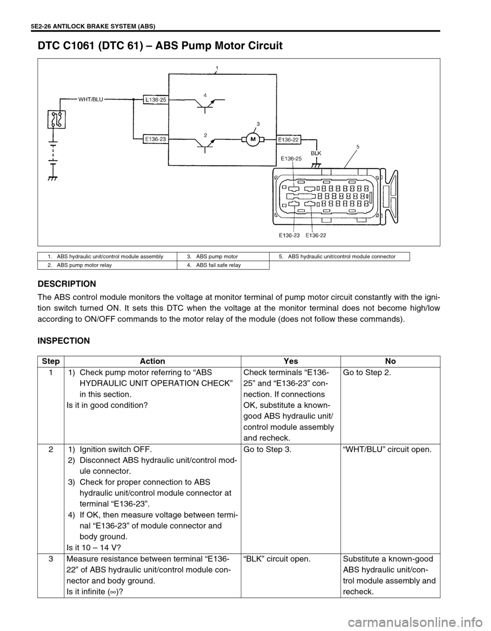
DTC C1061 (DTC 61) – ABS Pump Motor Circuit
DESCRIPTION
The ABS control module monitors the voltage at monitor terminal of pump motor circuit constantly with the igni-
tion switch turned ON. It sets this DTC when the voltage at the monitor terminal does not become high/low
according to ON/OFF commands to the motor relay of the module (does not follow these commands).
INSPECTION
1. ABS hydraulic unit/control module assembly 3. ABS pump motor 5. ABS hydraulic unit/control module connector
2. ABS pump motor relay 4. ABS fail safe relay
Step Action Yes No
1 1) Check pump motor referring to “ABS
HYDRAULIC UNIT OPERATION CHECK”
in this section.
Is it in good condition?Check terminals “E136-
25” and “E136-23” con-
nection. If connections
OK, substitute a known-
good ABS hydraulic unit/
control module assembly
and recheck.Go to Step 2.
2 1) Ignition switch OFF.
2) Disconnect ABS hydraulic unit/control mod-
ule connector.
3) Check for proper connection to ABS
hydraulic unit/control module connector at
terminal “E136-23”.
4) If OK, then measure voltage between termi-
nal “E136-23” of module connector and
body ground.
Is it 10 – 14 V?Go to Step 3.“WHT/BLU” circuit open.
3 Measure resistance between terminal “E136-
22” of ABS hydraulic unit/control module con-
nector and body ground.
Is it infinite (∞)?“BLK” circuit open. Substitute a known-good
ABS hydraulic unit/con-
trol module assembly and
recheck.
Page 152 of 656
ANTILOCK BRAKE SYSTEM (ABS) 5E2-27
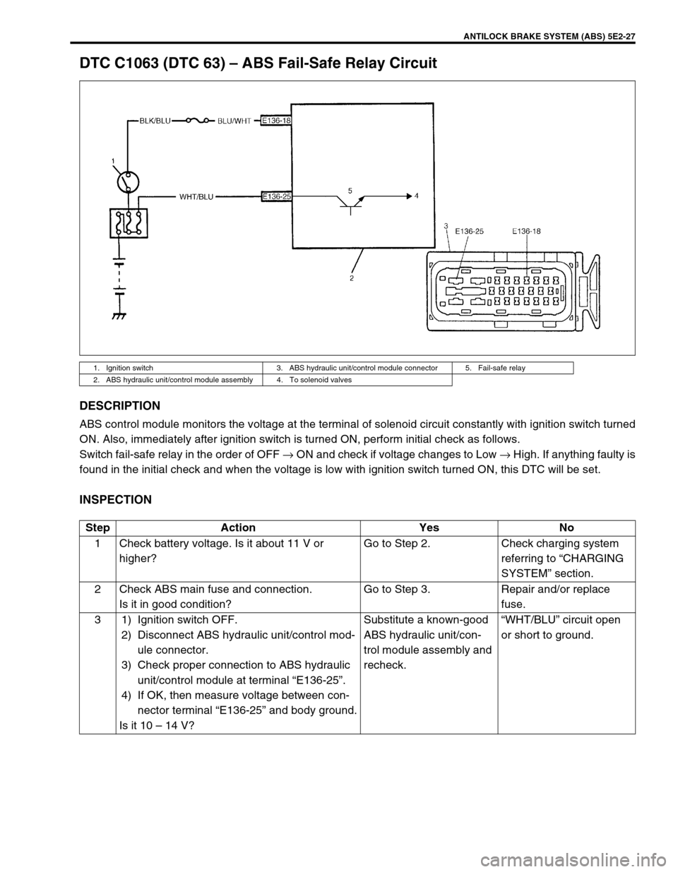
DTC C1063 (DTC 63) – ABS Fail-Safe Relay Circuit
DESCRIPTION
ABS control module monitors the voltage at the terminal of solenoid circuit constantly with ignition switch turned
ON. Also, immediately after ignition switch is turned ON, perform initial check as follows.
Switch fail-safe relay in the order of OFF → ON and check if voltage changes to Low → High. If anything faulty is
found in the initial check and when the voltage is low with ignition switch turned ON, this DTC will be set.
INSPECTION
1. Ignition switch 3. ABS hydraulic unit/control module connector 5. Fail-safe relay
2. ABS hydraulic unit/control module assembly 4. To solenoid valves
Step Action Yes No
1 Check battery voltage. Is it about 11 V or
higher?Go to Step 2. Check charging system
referring to “CHARGING
SYSTEM” section.
2 Check ABS main fuse and connection.
Is it in good condition?Go to Step 3. Repair and/or replace
fuse.
3 1) Ignition switch OFF.
2) Disconnect ABS hydraulic unit/control mod-
ule connector.
3) Check proper connection to ABS hydraulic
unit/control module at terminal “E136-25”.
4) If OK, then measure voltage between con-
nector terminal “E136-25” and body ground.
Is it 10 – 14 V?Substitute a known-good
ABS hydraulic unit/con-
trol module assembly and
recheck.“WHT/BLU” circuit open
or short to ground.
Page 154 of 656

ANTILOCK BRAKE SYSTEM (ABS) 5E2-29
On-Vehicle Service
Precautions
When connector are connected to ABS hydraulic unit/control
module assembly, do not disconnect connectors of sensors and
turn ignition switch ON. Then DTC will be set in ABS control mod-
ule.
ABS Hydraulic Unit Operation Check (Using
SUZUKI Scan Tool)
1) Connect SUZUKI scan tool to data link connector (DLC) (1)
with ignition switch OFF.
Special tool
(A) : SUZUKI scan tool
2) Turn ignition switch to ON position and check actuator opera-
tion using “HYDRAULIC CONTROL TEST” under “miscella-
neous test” (“MISC. TEST”) mode of SUZUKI scan tool.
ABS Hydraulic Unit Operation Check
(Not Using Suzuki Scan Tool)
1) Check that basic brake system other than ABS is in good
condition.
2) Check that battery voltage is 11V or higher.
3) With “ABS” warning lamp, check that no abnormality is
detected in ABS. Refer to “DIAGNOSTIC TROUBLE CODE
(DTC) CHECK” in this section.
4) Lift up vehicle.
5) Set transmission to neutral and release parking brake.
6) Turn each wheel gradually by hand to check if brake drag-
ging occurs. If it does, correct.
7) With diag. switch terminal (2) of diagnosis connector (1) con-
nected to ground by using service wire (4), turn ignition
switch to ON position and check that “ABS” warning lamp
indicates normal DTC (DTC 12) referring to “DIAGNOSTIC
TROUBLE CODE (DTC) TABLE” in this section.
8) Turn ignition switch to OFF position.
Page 155 of 656
5E2-30 ANTILOCK BRAKE SYSTEM (ABS)
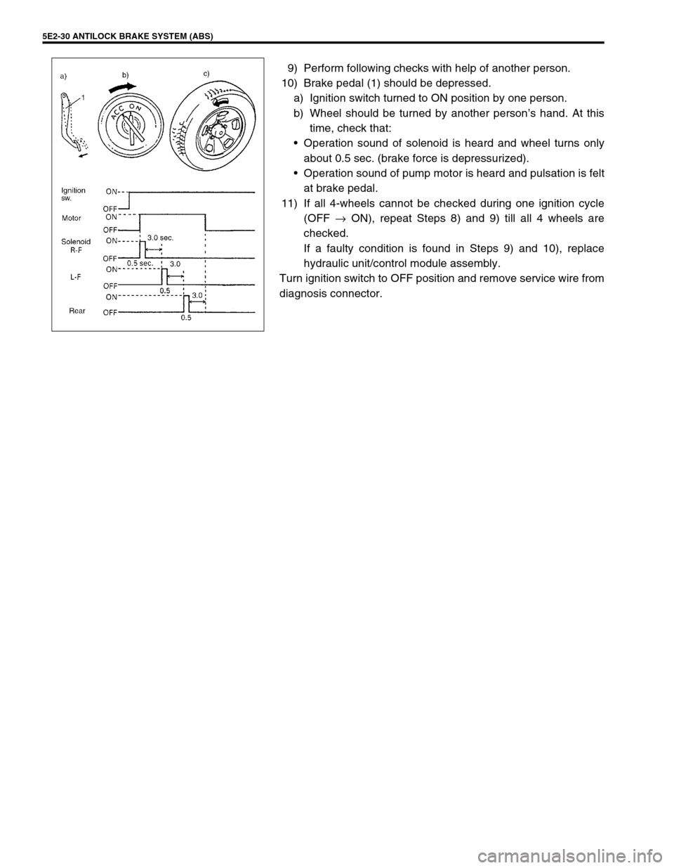
9) Perform following checks with help of another person.
10) Brake pedal (1) should be depressed.
a) Ignition switch turned to ON position by one person.
b) Wheel should be turned by another person’s hand. At this
time, check that:
Operation sound of solenoid is heard and wheel turns only
about 0.5 sec. (brake force is depressurized).
Operation sound of pump motor is heard and pulsation is felt
at brake pedal.
11) If all 4-wheels cannot be checked during one ignition cycle
(OFF → ON), repeat Steps 8) and 9) till all 4 wheels are
checked.
If a faulty condition is found in Steps 9) and 10), replace
hydraulic unit/control module assembly.
Turn ignition switch to OFF position and remove service wire from
diagnosis connector.
Page 157 of 656
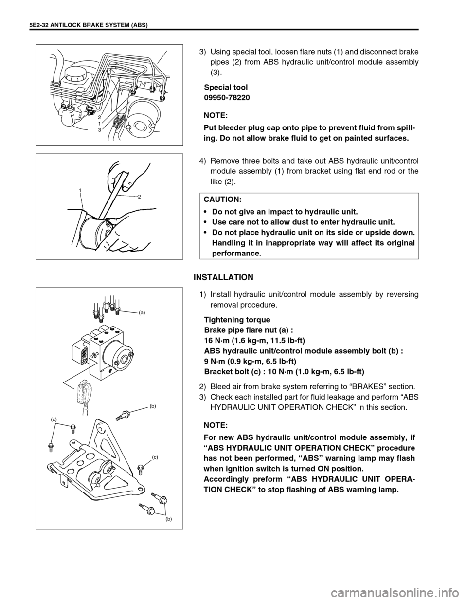
5E2-32 ANTILOCK BRAKE SYSTEM (ABS)
3) Using special tool, loosen flare nuts (1) and disconnect brake
pipes (2) from ABS hydraulic unit/control module assembly
(3).
Special tool
09950-78220
4) Remove three bolts and take out ABS hydraulic unit/control
module assembly (1) from bracket using flat end rod or the
like (2).
INSTALLATION
1) Install hydraulic unit/control module assembly by reversing
removal procedure.
Tightening torque
Brake pipe flare nut (a) :
16 N·m (1.6 kg-m, 11.5 lb-ft)
ABS hydraulic unit/control module assembly bolt (b) :
9 N·m (0.9 kg-m, 6.5 lb-ft)
Bracket bolt (c) : 10 N·m (1.0 kg-m, 6.5 lb-ft)
2) Bleed air from brake system referring to “BRAKES” section.
3) Check each installed part for fluid leakage and perform “ABS
HYDRAULIC UNIT OPERATION CHECK” in this section. NOTE:
Put bleeder plug cap onto pipe to prevent fluid from spill-
ing. Do not allow brake fluid to get on painted surfaces.
2
1
3
CAUTION:
Do not give an impact to hydraulic unit.
Use care not to allow dust to enter hydraulic unit.
Do not place hydraulic unit on its side or upside down.
Handling it in inappropriate way will affect its original
performance.
NOTE:
For new ABS hydraulic unit/control module assembly, if
“ABS HYDRAULIC UNIT OPERATION CHECK” procedure
has not been performed, “ABS” warning lamp may flash
when ignition switch is turned ON position.
Accordingly preform “ABS HYDRAULIC UNIT OPERA-
TION CHECK” to stop flashing of ABS warning lamp.
(b) (b) (a)
(c) (c)
Page 166 of 656

ENGINE GENERAL INFORMATION AND DIAGNOSIS (H27 ENGINE) 6-1-5
Fuel Pressure Relief Procedure
After making sure that engine is cold, relief fuel pressure as fol-
lows.
1) Place transmission gear shift lever in “Neutral” (shift selector
lever to “P” range for A/T vehicle), set parking brake, and
block drive wheels.
2) Remove fuel pump relay (1) from its connector.
3) Remove fuel filler cap to release fuel vapor pressure in fuel
tank and then reinstall it.
4) Start engine and run it till it stops for lack of fuel. Repeat
cranking engine 2 – 3 times of about 3 seconds each time to
dissipate fuel pressure in lines. Fuel connections are now
safe for servicing.
5) Upon completion of servicing, install fuel pump relay to relay
box.
Fuel Leakage Check Procedure
After performing any service on fuel system, check to make sure
that there are no fuel leakages as follows.
1) Turn ON ignition switch for 3 seconds (to operate fuel pump)
and then turn it OFF.
Repeat this (ON and OFF) 3 or 4 times and apply fuel pres-
sure to fuel line (till fuel pressure is felt by hand placed on
fuel return hose).
2) In this state, check to see that there are no fuel leakages
from any part of fuel system. CAUTION:
This work must not be done when engine is hot. If done
so, it may cause adverse effect to catalyst.
[A] : Left hand steering vehicle
[B] : Right hand steering vehicle
2. Fuse box
Page 185 of 656
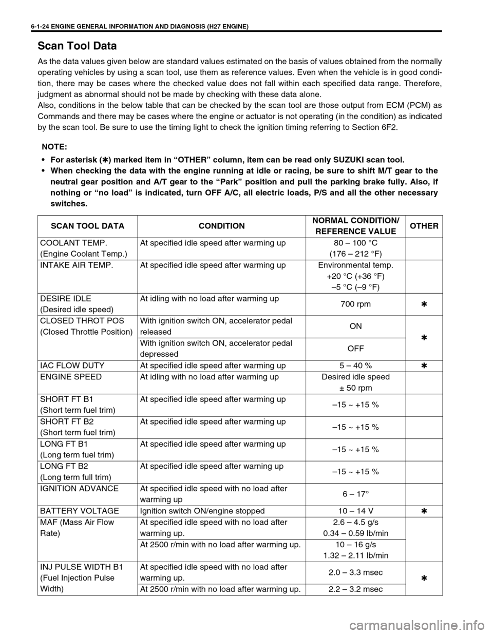
6-1-24 ENGINE GENERAL INFORMATION AND DIAGNOSIS (H27 ENGINE)
Scan Tool Data
As the data values given below are standard values estimated on the basis of values obtained from the normally
operating vehicles by using a scan tool, use them as reference values. Even when the vehicle is in good condi-
tion, there may be cases where the checked value does not fall within each specified data range. Therefore,
judgment as abnormal should not be made by checking with these data alone.
Also, conditions in the below table that can be checked by the scan tool are those output from ECM (PCM) as
Commands and there may be cases where the engine or actuator is not operating (in the condition) as indicated
by the scan tool. Be sure to use the timing light to check the ignition timing referring to Section 6F2.
NOTE:
For asterisk (
✱) marked item in “OTHER” column, item can be read only SUZUKI scan tool.
When checking the data with the engine running at idle or racing, be sure to shift M/T gear to the
neutral gear position and A/T gear to the “Park” position and pull the parking brake fully. Also, if
nothing or “no load” is indicated, turn OFF A/C, all electric loads, P/S and all the other necessary
switches.
SCAN TOOL DATA CONDITIONNORMAL CONDITION/
REFERENCE VALUEOTHER
COOLANT TEMP.
(Engine Coolant Temp.)At specified idle speed after warming up 80 – 100 °C
(176 – 212 °F)
INTAKE AIR TEMP. At specified idle speed after warming up Environmental temp.
+20 °C (+36 °F)
–5 °C (–9 °F)
DESIRE IDLE
(Desired idle speed)At idling with no load after warming up
700 rpm✱
CLOSED THROT POS
(Closed Throttle Position)With ignition switch ON, accelerator pedal
releasedON
✱
With ignition switch ON, accelerator pedal
depressedOFF
IAC FLOW DUTY At specified idle speed after warming up 5 – 40 %✱
ENGINE SPEED At idling with no load after warming up Desired idle speed
± 50 rpm
SHORT FT B1
(Short term fuel trim)At specified idle speed after warming up
–15 ~ +15 %
SHORT FT B2
(Short term fuel trim)At specified idle speed after warming up
–15 ~ +15 %
LONG FT B1
(Long term fuel trim)At specified idle speed after warming up
–15 ~ +15 %
LONG FT B2
(Long term full trim)At specified idle speed after warning up
–15 ~ +15 %
IGNITION ADVANCE At specified idle speed with no load after
warming up6 – 17°
BATTERY VOLTAGE Ignition switch ON/engine stopped 10 – 14 V✱
MAF (Mass Air Flow
Rate)At specified idle speed with no load after
warming up.2.6 – 4.5 g/s
0.34 – 0.59 lb/min
At 2500 r/min with no load after warming up. 10 – 16 g/s
1.32 – 2.11 lb/min
INJ PULSE WIDTH B1
(Fuel Injection Pulse
Width)At specified idle speed with no load after
warming up.2.0 – 3.3 msec
✱
At 2500 r/min with no load after warming up. 2.2 – 3.2 msec