Page 1105 of 1456
4. Front Door Glass
B5M0054B
(1) Glass
(2) Regulator and motor ASSY
(3) Regulator handle (Except power
window)(4) Retainer spring
(5) Regulator ASSYTightening torque: N´m (kg-m, ft-lb)
T:
7.4±2.0 (0.75±0.2, 5.4±1.4)
6
5-2[C400]COMPONENT PARTS
4. Front Door Glass
Page 1106 of 1456
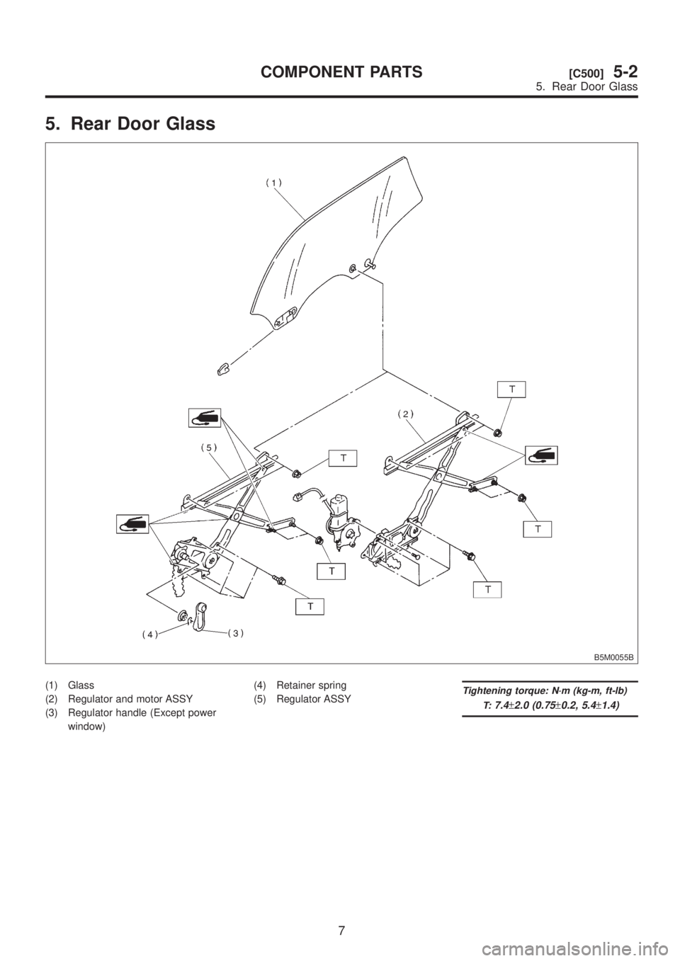
5. Rear Door Glass
B5M0055B
(1) Glass
(2) Regulator and motor ASSY
(3) Regulator handle (Except power
window)(4) Retainer spring
(5) Regulator ASSYTightening torque: N´m (kg-m, ft-lb)
T:
7.4±2.0 (0.75±0.2, 5.4±1.4)
7
[C500]5-2COMPONENT PARTS
5. Rear Door Glass
Page 1113 of 1456
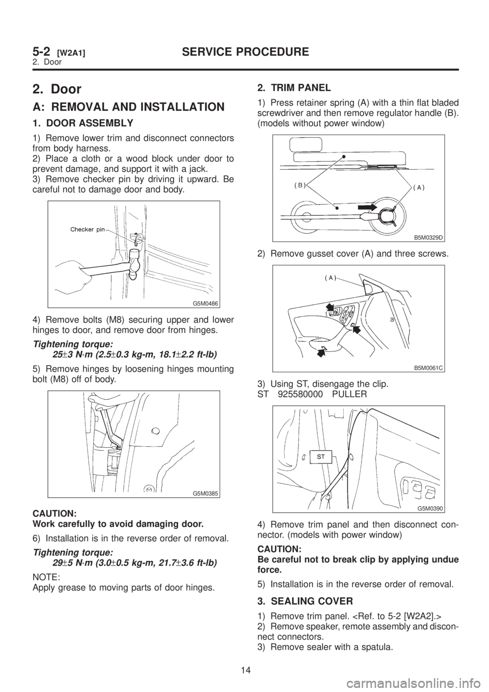
2. Door
A: REMOVAL AND INSTALLATION
1. DOOR ASSEMBLY
1) Remove lower trim and disconnect connectors
from body harness.
2) Place a cloth or a wood block under door to
prevent damage, and support it with a jack.
3) Remove checker pin by driving it upward. Be
careful not to damage door and body.
G5M0486
4) Remove bolts (M8) securing upper and lower
hinges to door, and remove door from hinges.
Tightening torque:
25
±3 N´m (2.5±0.3 kg-m, 18.1±2.2 ft-lb)
5) Remove hinges by loosening hinges mounting
bolt (M8) off of body.
G5M0385
CAUTION:
Work carefully to avoid damaging door.
6) Installation is in the reverse order of removal.
Tightening torque:
29
±5 N´m (3.0±0.5 kg-m, 21.7±3.6 ft-lb)
NOTE:
Apply grease to moving parts of door hinges.
2. TRIM PANEL
1) Press retainer spring (A) with a thin flat bladed
screwdriver and then remove regulator handle (B).
(models without power window)
B5M0329D
2) Remove gusset cover (A) and three screws.
B5M0061C
3) Using ST, disengage the clip.
ST 925580000 PULLER
G5M0390
4) Remove trim panel and then disconnect con-
nector. (models with power window)
CAUTION:
Be careful not to break clip by applying undue
force.
5) Installation is in the reverse order of removal.
3. SEALING COVER
1) Remove trim panel.
2) Remove speaker, remote assembly and discon-
nect connectors.
3) Remove sealer with a spatula.
14
5-2[W2A1]SERVICE PROCEDURE
2. Door
Page 1259 of 1456
3. HORN
Make sure that horn sounds when battery voltage
is applied between connector terminal and horn
body.
B6M0127
4. CIGARETTE LIGHTER
1) Remove plug. Then, check element's contact
for wear, and element for accumulation of ashes,
foreign particles, etc.
2) Check element for discontinuity.
3) Remove socket and clean element. Then,
check for wear or foreign particles on element's
contact and mating surface.
4) Ensure that cigarette lighter returns within 20
seconds after it is turned to ON.
17. Power Window
A: REMOVAL AND INSTALLATION
1. MAIN SWITCH, SUB SWITCH AND
POWER WINDOW MOTOR
Remove and install power window main switch,
sub switch and motor.
NOTE:
To remove the power window motor, it is necessary
to disassemble the door component parts.
B: INSPECTION
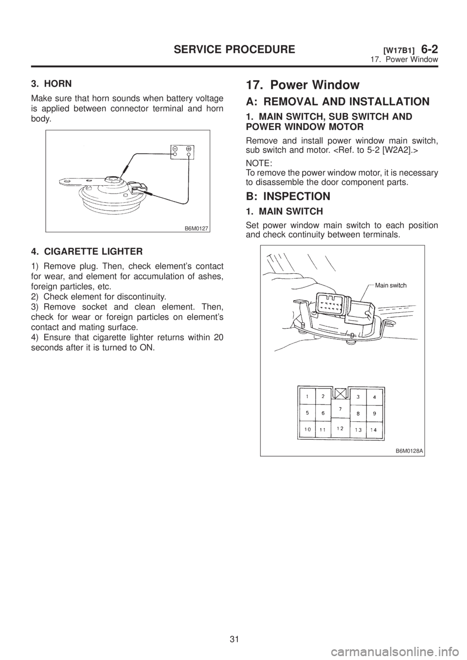
1. MAIN SWITCH
Set power window main switch to each position
and check continuity between terminals.
B6M0128A
31
[W17B1]6-2SERVICE PROCEDURE
17. Power Window
Page 1260 of 1456
3. HORN
Make sure that horn sounds when battery voltage
is applied between connector terminal and horn
body.
B6M0127
4. CIGARETTE LIGHTER
1) Remove plug. Then, check element's contact
for wear, and element for accumulation of ashes,
foreign particles, etc.
2) Check element for discontinuity.
3) Remove socket and clean element. Then,
check for wear or foreign particles on element's
contact and mating surface.
4) Ensure that cigarette lighter returns within 20
seconds after it is turned to ON.
17. Power Window
A: REMOVAL AND INSTALLATION
1. MAIN SWITCH, SUB SWITCH AND
POWER WINDOW MOTOR
Remove and install power window main switch,
sub switch and motor.
NOTE:
To remove the power window motor, it is necessary
to disassemble the door component parts.
B: INSPECTION
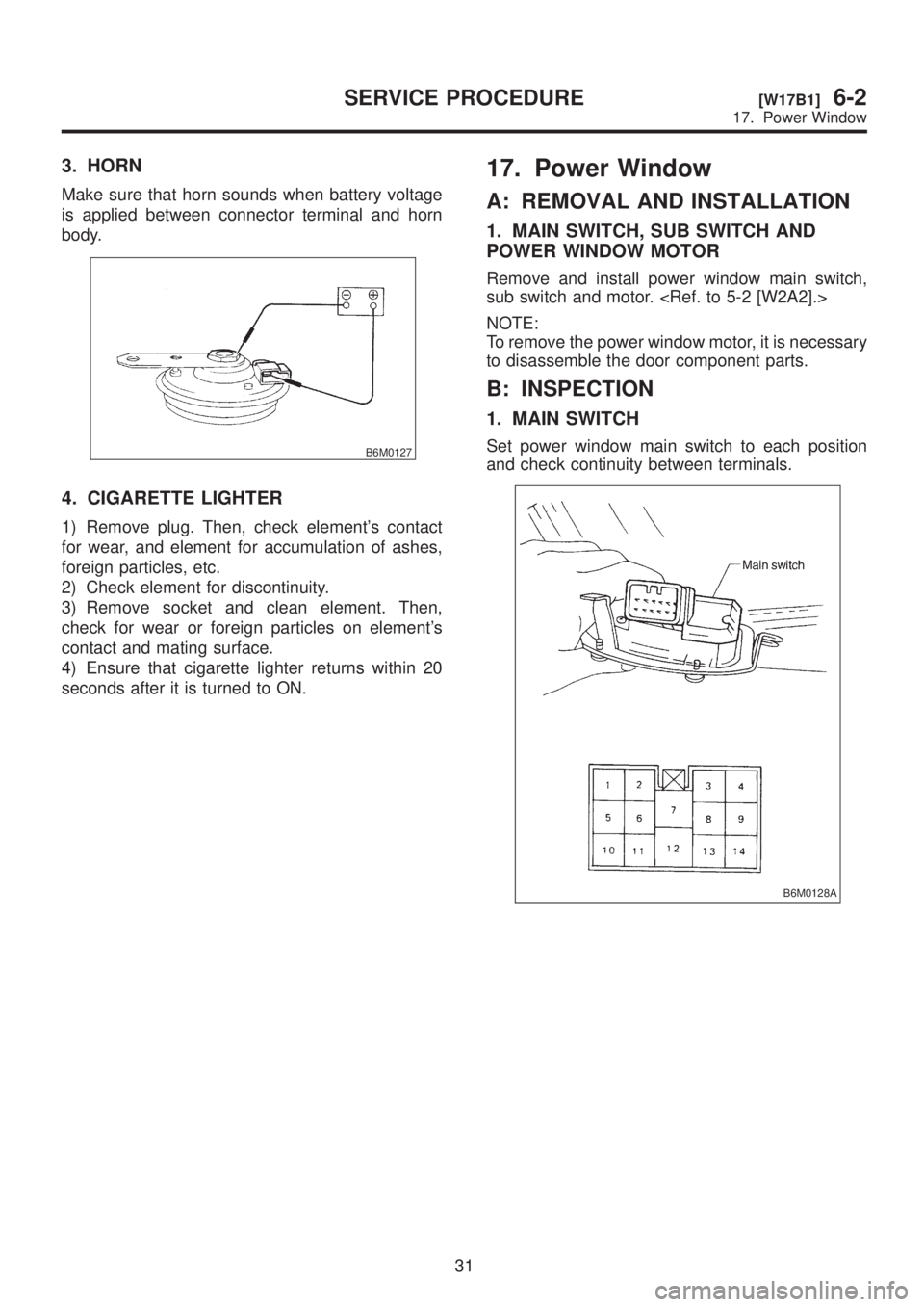
1. MAIN SWITCH
Set power window main switch to each position
and check continuity between terminals.
B6M0128A
31
[W17B1]6-2SERVICE PROCEDURE
17. Power Window
Page 1261 of 1456
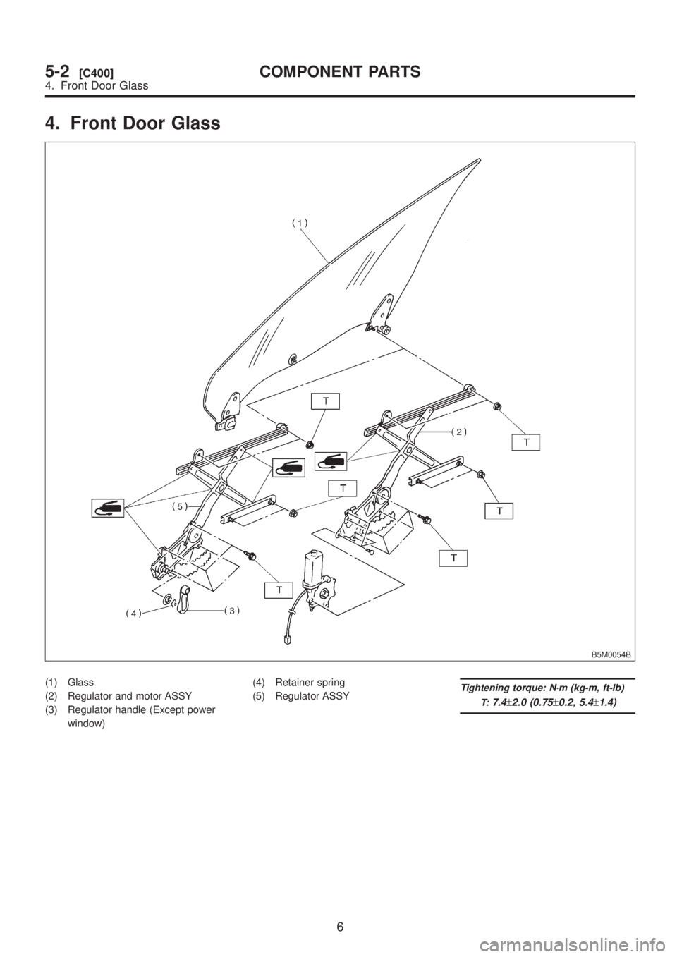
B6M0711
2. SUB SWITCH
Set power window sub switch to each position and
check continuity between terminals.
B6M0130A
32
6-2[W17B2]SERVICE PROCEDURE
17. Power Window
Page 1262 of 1456
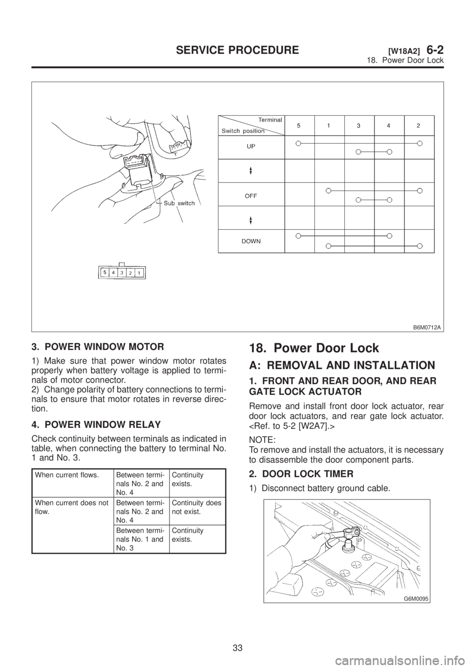
B6M0712A
3. POWER WINDOW MOTOR
1) Make sure that power window motor rotates
properly when battery voltage is applied to termi-
nals of motor connector.
2) Change polarity of battery connections to termi-
nals to ensure that motor rotates in reverse direc-
tion.
4. POWER WINDOW RELAY
Check continuity between terminals as indicated in
table, when connecting the battery to terminal No.
1 and No. 3.
When current flows. Between termi-
nals No. 2 and
No. 4Continuity
exists.
When current does not
flow.Between termi-
nals No. 2 and
No. 4Continuity does
not exist.
Between termi-
nals No. 1 and
No. 3Continuity
exists.
18. Power Door Lock
A: REMOVAL AND INSTALLATION
1. FRONT AND REAR DOOR, AND REAR
GATE LOCK ACTUATOR
Remove and install front door lock actuator, rear
door lock actuators, and rear gate lock actuator.
NOTE:
To remove and install the actuators, it is necessary
to disassemble the door component parts.
2. DOOR LOCK TIMER
1) Disconnect battery ground cable.
G6M0095
33
[W18A2]6-2SERVICE PROCEDURE
18. Power Door Lock
Page 1263 of 1456
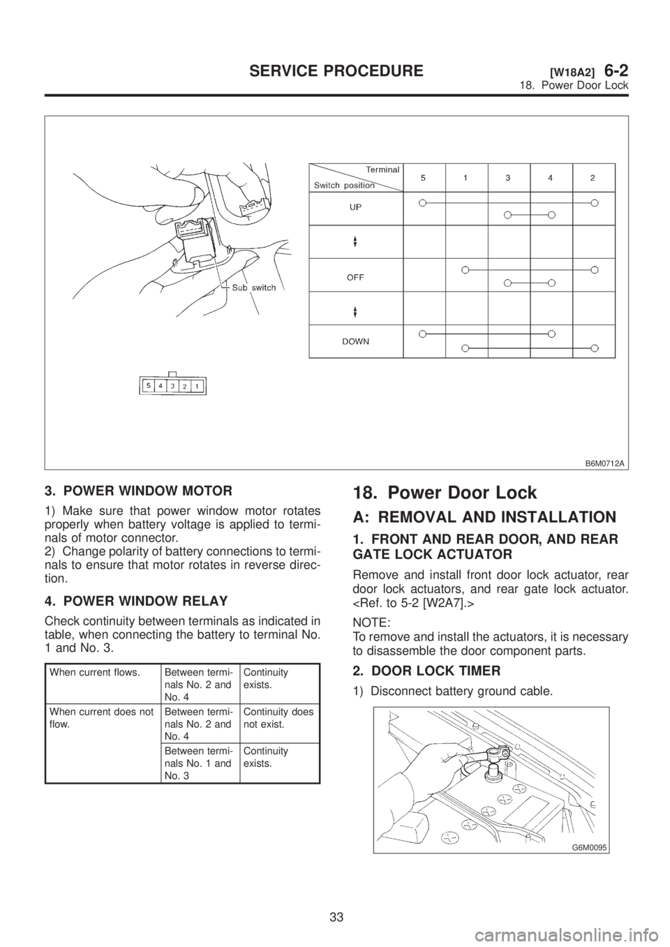
B6M0712A
3. POWER WINDOW MOTOR
1) Make sure that power window motor rotates
properly when battery voltage is applied to termi-
nals of motor connector.
2) Change polarity of battery connections to termi-
nals to ensure that motor rotates in reverse direc-
tion.
4. POWER WINDOW RELAY
Check continuity between terminals as indicated in
table, when connecting the battery to terminal No.
1 and No. 3.
When current flows. Between termi-
nals No. 2 and
No. 4Continuity
exists.
When current does not
flow.Between termi-
nals No. 2 and
No. 4Continuity does
not exist.
Between termi-
nals No. 1 and
No. 3Continuity
exists.
18. Power Door Lock
A: REMOVAL AND INSTALLATION
1. FRONT AND REAR DOOR, AND REAR
GATE LOCK ACTUATOR
Remove and install front door lock actuator, rear
door lock actuators, and rear gate lock actuator.
NOTE:
To remove and install the actuators, it is necessary
to disassemble the door component parts.
2. DOOR LOCK TIMER
1) Disconnect battery ground cable.
G6M0095
33
[W18A2]6-2SERVICE PROCEDURE
18. Power Door Lock
![SUBARU LEGACY 1999 Service Repair Manual B6M0711
2. SUB SWITCH
Set power window sub switch to each position and
check continuity between terminals.
B6M0130A
32
6-2[W17B2]SERVICE PROCEDURE
17. Power Window](/manual-img/17/57435/w960_57435-1260.png "SUBARU LEGACY 1999 Service Repair Manual B6M0711
2. SUB SWITCH
Set power window sub switch to each position and
check continuity between terminals.
B6M0130A
32
6-2[W17B2]SERVICE PROCEDURE
17. Power Window")