Page 450 of 1456

7) Install canister and bracket.
(1) Install power stering pump on bracket, and
tighten bolts.
Tightening torque:
39
±10 N´m (4.0±1.0 kg-m, 29±7 ft-lb)
S2M0086
(2) Install power steering pipe bracket on right
side intake manifold, and install spark plug
codes.
B2M2309
(3) Install front side V-belt, and adjust it.
G2M0286
8) Tighten nuts which hold lower side of transmis-
sion to engine.
Tightening torque:
50
±4 N´m (5.1±0.4 kg-m, 36.9±2.9 ft-lb)
B2M2790
9) Tighten nuts which install front cushion rubber
onto crossmember.
Tightening torque:
69
±15 N´m (7.0±1.5 kg-m, 51±11 ft-lb)
CAUTION:
Be sure to tighten front cushion rubber mount-
ing bolts in the innermost elliptical hole in the
front crossmember.
G2M0303
10) Install front exhaust pipe and center exhaust
pipe.
11) Connect the following hoses.
(1) Fuel delivery hose, return hose and evapo-
ration hose
(2) Heater inlet and outlet hoses
(3) Brake booster vacuum hose
12) Connect the following connectors.
(1) Engine ground terminal
(2) Engine harness connectors
(3) Front oxygen sensor connector
(4) Rear oxygen sensor connector (California
spec. vehicles)
(5) Alternator connector and terminal
(6) A/C compressor connectors (With A/C)
13) Connect the following cables.
(1) Accelerator cable
(2) Cruise control cables (With cruise control)
(3) Clutch cable (2200 cc MT vehicles)
18
2-11[W1C0]SERVICE PROCEDURE
1. Engine
Page 661 of 1456
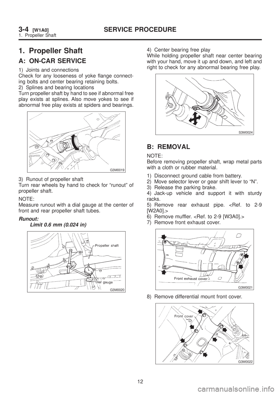
1. Propeller Shaft
A: ON-CAR SERVICE
1) Joints and connections
Check for any looseness of yoke flange connect-
ing bolts and center bearing retaining bolts.
2) Splines and bearing locations
Turn propeller shaft by hand to see if abnormal free
play exists at splines. Also move yokes to see if
abnormal free play exists at spiders and bearings.
G3M0019
3) Runout of propeller shaft
Turn rear wheels by hand to check for ªrunoutº of
propeller shaft.
NOTE:
Measure runout with a dial gauge at the center of
front and rear propeller shaft tubes.
Runout:
Limit 0.6 mm (0.024 in)
G3M0020
4) Center bearing free play
While holding propeller shaft near center bearing
with your hand, move it up and down, and left and
right to check for any abnormal bearing free play.
S3M0024
B: REMOVAL
NOTE:
Before removing propeller shaft, wrap metal parts
with a cloth or rubber material.
1) Disconnect ground cable from battery.
2) Move selector lever or gear shift lever to ªNº.
3) Release the parking brake.
4) Jack-up vehicle and support it with sturdy
racks.
5) Remove rear exhaust pipe.
[W2A0].>
6) Remove muffler.
7) Remove front exhaust cover.
G3M0021
8) Remove differential mount front cover.
G3M0022
12
3-4[W1A0]SERVICE PROCEDURE
1. Propeller Shaft
Page 941 of 1456

4) Install front ABS sensor on strut and wheel
apron bracket.
Tightening torque:
32
±10 N´m (3.3±1.0 kg-m, 24±7 ft-lb)
B4M1442A
5) Place a thickness gauge between ABS sensor's
pole piece and tone wheel's tooth face. After stan-
dard clearance is obtained over the entire
perimeter, tighten ABS sensor on housing to speci-
fied torque.
ABS sensor standard clearance:
0.9 Ð 1.4 mm (0.035 Ð 0.055 in)
Tightening torque:
32
±10 N´m (3.3±1.0 kg-m, 24±7 ft-lb)
CAUTION:
Check the marks on the harness to make sure
that no distortion exists. (RH: white, LH: yel-
low)
NOTE:
If the clearance is outside specifications, readjust.
17. Brake Pipe
A: SUPPLEMENTAL RESTRAINT
SYSTEM ªAIRBAGº
Airbag system wiring harness is routed near the
center brake pipe.
CAUTION:
IAll Airbag system wiring harness and con-
nectors are colored yellow. Do not use electri-
cal test equipment on these circuit.
IBe careful not to damage Airbag system wir-
ing harness when servicing the center brake
pipe.
B: REMOVAL AND INSTALLATION
CAUTION:
IWhen removing and installing the brake
pipe, make sure that it is not bent.
IAfter installing the brake pipe and hose,
bleed the air.
IAfter installing the brake hose, make sure
that it does not touch the tire or suspension
assembly, etc.
Brake pipe tightening torque:
15+3/þ2N´m (1.5+0.3/þ0.2kg-m, 10.8+2.2/þ1.4ft-lb)
63
[W17B0]4-4SERVICE PROCEDURE
17. Brake Pipe
Page 942 of 1456

4) Install front ABS sensor on strut and wheel
apron bracket.
Tightening torque:
32
±10 N´m (3.3±1.0 kg-m, 24±7 ft-lb)
B4M1442A
5) Place a thickness gauge between ABS sensor's
pole piece and tone wheel's tooth face. After stan-
dard clearance is obtained over the entire
perimeter, tighten ABS sensor on housing to speci-
fied torque.
ABS sensor standard clearance:
0.9 Ð 1.4 mm (0.035 Ð 0.055 in)
Tightening torque:
32
±10 N´m (3.3±1.0 kg-m, 24±7 ft-lb)
CAUTION:
Check the marks on the harness to make sure
that no distortion exists. (RH: white, LH: yel-
low)
NOTE:
If the clearance is outside specifications, readjust.
17. Brake Pipe
A: SUPPLEMENTAL RESTRAINT
SYSTEM ªAIRBAGº
Airbag system wiring harness is routed near the
center brake pipe.
CAUTION:
IAll Airbag system wiring harness and con-
nectors are colored yellow. Do not use electri-
cal test equipment on these circuit.
IBe careful not to damage Airbag system wir-
ing harness when servicing the center brake
pipe.
B: REMOVAL AND INSTALLATION
CAUTION:
IWhen removing and installing the brake
pipe, make sure that it is not bent.
IAfter installing the brake pipe and hose,
bleed the air.
IAfter installing the brake hose, make sure
that it does not touch the tire or suspension
assembly, etc.
Brake pipe tightening torque:
15+3/þ2N´m (1.5+0.3/þ0.2kg-m, 10.8+2.2/þ1.4ft-lb)
63
[W17B0]4-4SERVICE PROCEDURE
17. Brake Pipe