1999 SUBARU LEGACY weight
[x] Cancel search: weightPage 789 of 1456
8. Aluminum Wheel
A: INSPECTION
Inspection for aluminum wheels is basically the
same as the one for steel wheels. However, check
the rim flange for cracks or damage, and replace
(not repair) aluminum wheel if air leakage is found.
B: PRECAUTIONS
Aluminum wheels are easily scratched. To main-
tain their appearance and safety, do the following:
1) Do not damage aluminum wheels during
removal, disassembly, installation, wheel
balancing, etc. After removing aluminum wheels,
place them on a rubber mat, etc.
2) While vehicle is being driven, be careful not to
ride over sharp obstacles or allow aluminum
wheels to contact the shoulder of the road.
3) When installing tire chain, be sure to install it
properly not to have a slack; otherwise it may hit
wheel while driving.
4) When washing aluminum wheel, use neutral
synthetic detergent and water. Avoid using the
cleanser including abrasive, hard brushes or an
automatic car washer.
9. Wheel Balancing
1) Proper wheel balance may be lost if the tire is
repaired or if it wears. Check the tire for dynamic
balance, and repair as necessary.
2) To check for dynamic balance, use a dynamic
balancer. Drive in the balance weight on both the
top and rear sides of the rim.
3) Some types of balancer can cause damage to
the wheel. Use an appropriate balancer when
adjusting the wheel balance.
4) Use genuine balance weights.
CAUTION:
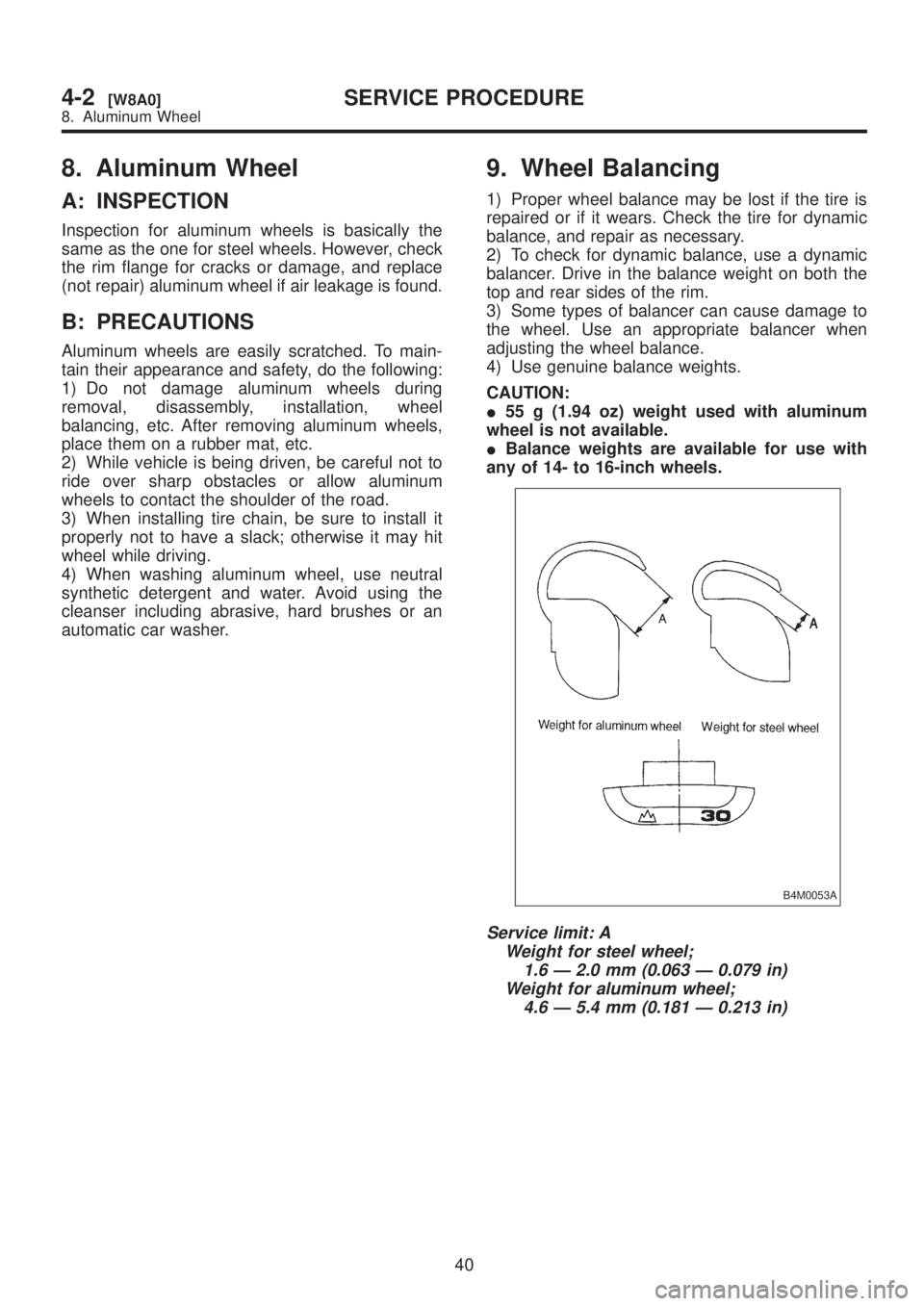
I55 g (1.94 oz) weight used with aluminum
wheel is not available.
IBalance weights are available for use with
any of 14- to 16-inch wheels.
B4M0053A
Service limit: A
Weight for steel wheel;
1.6 Ð 2.0 mm (0.063 Ð 0.079 in)
Weight for aluminum wheel;
4.6 Ð 5.4 mm (0.181 Ð 0.213 in)
40
4-2[W8A0]SERVICE PROCEDURE
8. Aluminum Wheel
Page 863 of 1456
1. Power Steering
A: STEERING CONDITION
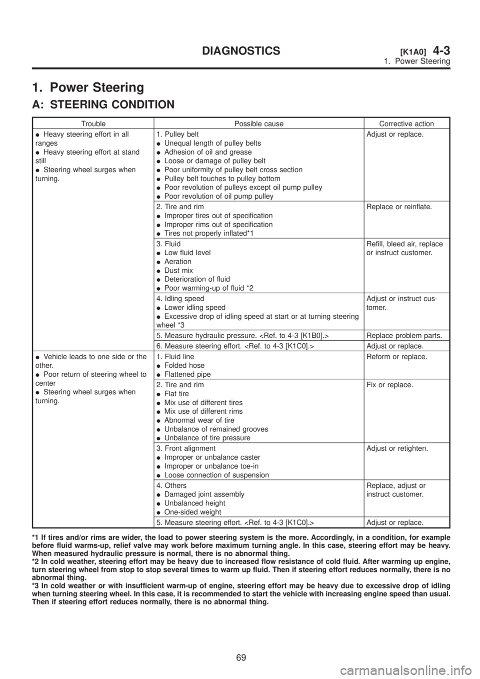
Trouble Possible cause Corrective action
IHeavy steering effort in all
ranges
IHeavy steering effort at stand
still
ISteering wheel surges when
turning.1. Pulley belt
IUnequal length of pulley belts
IAdhesion of oil and grease
ILoose or damage of pulley belt
IPoor uniformity of pulley belt cross section
IPulley belt touches to pulley bottom
IPoor revolution of pulleys except oil pump pulley
IPoor revolution of oil pump pulleyAdjust or replace.
2. Tire and rim
IImproper tires out of specification
IImproper rims out of specification
ITires not properly inflated*1Replace or reinflate.
3. Fluid
ILow fluid level
IAeration
IDust mix
IDeterioration of fluid
IPoor warming-up of fluid *2Refill, bleed air, replace
or instruct customer.
4. Idling speed
ILower idling speed
IExcessive drop of idling speed at start or at turning steering
wheel *3Adjust or instruct cus-
tomer.
5. Measure hydraulic pressure.
6. Measure steering effort.
IVehicle leads to one side or the
other.
IPoor return of steering wheel to
center
ISteering wheel surges when
turning.1. Fluid line
IFolded hose
IFlattened pipeReform or replace.
2. Tire and rim
IFlat tire
IMix use of different tires
IMix use of different rims
IAbnormal wear of tire
IUnbalance of remained grooves
IUnbalance of tire pressureFix or replace.
3. Front alignment
IImproper or unbalance caster
IImproper or unbalance toe-in
ILoose connection of suspensionAdjust or retighten.
4. Others
IDamaged joint assembly
IUnbalanced height
IOne-sided weightReplace, adjust or
instruct customer.
5. Measure steering effort.
*1 If tires and/or rims are wider, the load to power steering system is the more. Accordingly, in a condition, for example
before fluid warms-up, relief valve may work before maximum turning angle. In this case, steering effort may be heavy.
When measured hydraulic pressure is normal, there is no abnormal thing.
*2 In cold weather, steering effort may be heavy due to increased flow resistance of cold fluid. After warming up engine,
turn steering wheel from stop to stop several times to warm up fluid. Then if steering effort reduces normally, there is no
abnormal thing.
*3 In cold weather or with insufficient warm-up of engine, steering effort may be heavy due to excessive drop of idling
when turning steering wheel. In this case, it is recommended to start the vehicle with increasing engine speed than usual.
Then if steering effort reduces normally, there is no abnormal thing.
69
[K1A0]4-3DIAGNOSTICS
1. Power Steering
Page 986 of 1456
Tools and Equipment Description
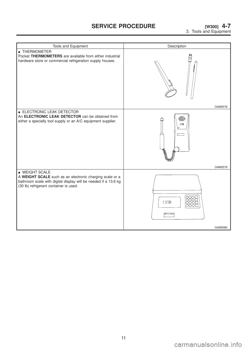
ITHERMOMETER
PocketTHERMOMETERSare available from either industrial
hardware store or commercial refrigeration supply houses.
G4M0578
IELECTRONIC LEAK DETECTOR
AnELECTRONIC LEAK DETECTORcan be obtained from
either a specially tool supply or an A/C equipment supplier.
G4M0579
IWEIGHT SCALE
AWEIGHT SCALEsuch as an electronic charging scale or a
bathroom scale with digital display will be needed if a 13.6 kg
(30 lb) refrigerant container is used.
G4M0580
11
[W300]4-7SERVICE PROCEDURE
3. Tools and Equipment
Page 992 of 1456
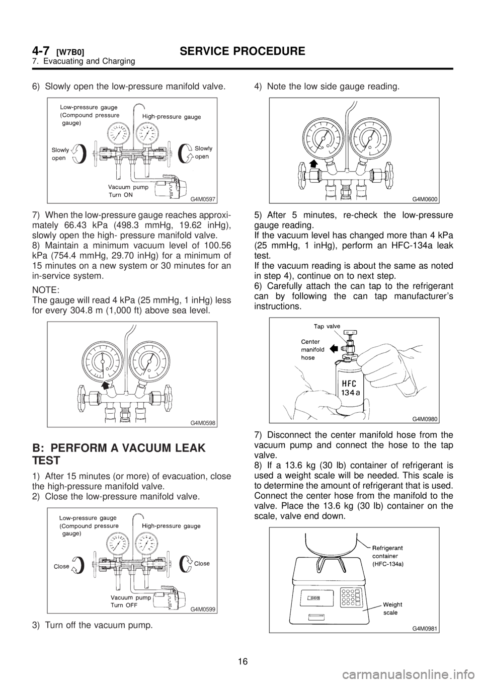
6) Slowly open the low-pressure manifold valve.
G4M0597
7) When the low-pressure gauge reaches approxi-
mately 66.43 kPa (498.3 mmHg, 19.62 inHg),
slowly open the high- pressure manifold valve.
8) Maintain a minimum vacuum level of 100.56
kPa (754.4 mmHg, 29.70 inHg) for a minimum of
15 minutes on a new system or 30 minutes for an
in-service system.
NOTE:
The gauge will read 4 kPa (25 mmHg, 1 inHg) less
for every 304.8 m (1,000 ft) above sea level.
G4M0598
B: PERFORM A VACUUM LEAK
TEST
1) After 15 minutes (or more) of evacuation, close
the high-pressure manifold valve.
2) Close the low-pressure manifold valve.
G4M0599
3) Turn off the vacuum pump.4) Note the low side gauge reading.
G4M0600
5) After 5 minutes, re-check the low-pressure
gauge reading.
If the vacuum level has changed more than 4 kPa
(25 mmHg, 1 inHg), perform an HFC-134a leak
test.
If the vacuum reading is about the same as noted
in step 4), continue on to next step.
6) Carefully attach the can tap to the refrigerant
can by following the can tap manufacturer's
instructions.
G4M0980
7) Disconnect the center manifold hose from the
vacuum pump and connect the hose to the tap
valve.
8) If a 13.6 kg (30 lb) container of refrigerant is
used a weight scale will be needed. This scale is
to determine the amount of refrigerant that is used.
Connect the center hose from the manifold to the
valve. Place the 13.6 kg (30 lb) container on the
scale, valve end down.
G4M0981
16
4-7[W7B0]SERVICE PROCEDURE
7. Evacuating and Charging
Page 1060 of 1456
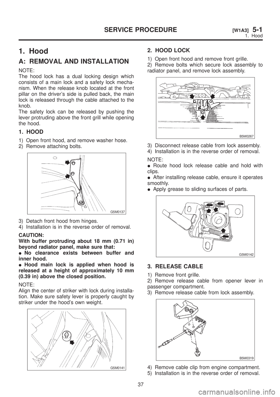
1. Hood
A: REMOVAL AND INSTALLATION
NOTE:
The hood lock has a dual locking design which
consists of a main lock and a safety lock mecha-
nism. When the release knob located at the front
pillar on the driver's side is pulled back, the main
lock is released through the cable attached to the
knob.
The safety lock can be released by pushing the
lever protruding above the front grill while opening
the hood.
1. HOOD
1) Open front hood, and remove washer hose.
2) Remove attaching bolts.
G5M0137
3) Detach front hood from hinges.
4) Installation is in the reverse order of removal.
CAUTION:
With buffer protruding about 18 mm (0.71 in)
beyond radiator panel, make sure that:
INo clearance exists between buffer and
inner hood.
IHood main lock is applied when hood is
released at a height of approximately 10 mm
(0.39 in) above the closed position.
NOTE:
Align the center of striker with lock during installa-
tion. Make sure safety lever is properly caught by
striker under the hood's own weight.
G5M0141
2. HOOD LOCK
1) Open front hood and remove front grille.
2) Remove bolts which secure lock assembly to
radiator panel, and remove lock assembly.
B5M0267
3) Disconnect release cable from lock assembly.
4) Installation is in the reverse order of removal.
NOTE:
IRoute hood lock release cable and hold with
clips.
IAfter installing release cable, ensure it operates
smoothly.
IApply grease to sliding surfaces of parts.
G5M0142
3. RELEASE CABLE
1) Remove front grille.
2) Remove release cable from opener lever in
passenger compartment.
3) Remove release cable from lock assembly.
B5M0319
4) Remove cable clip from engine compartment.
5) Installation is in the reverse order of removal.
37
[W1A3]5-1SERVICE PROCEDURE
1. Hood
Page 1062 of 1456
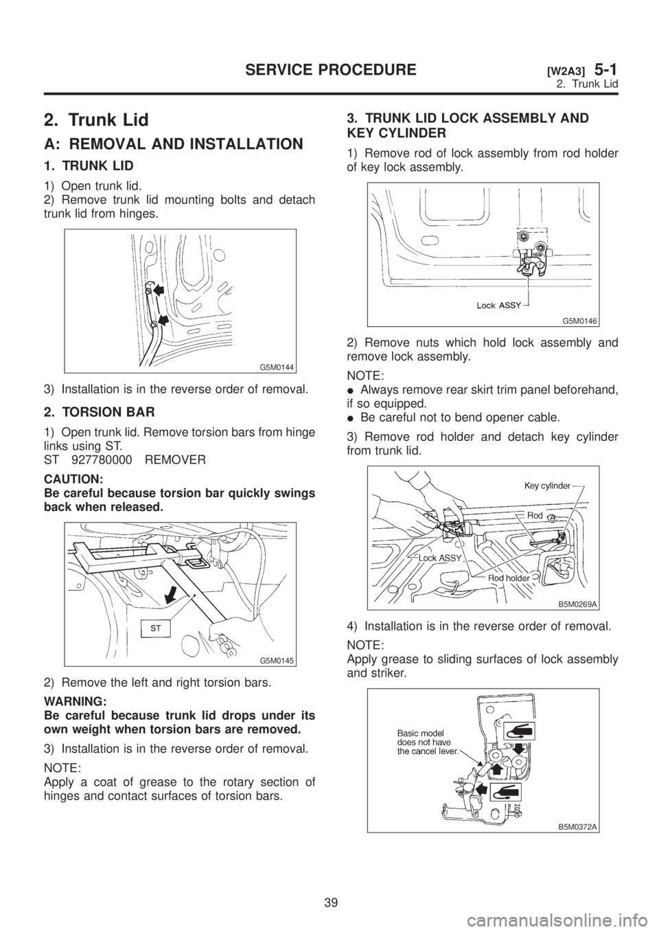
2. Trunk Lid
A: REMOVAL AND INSTALLATION
1. TRUNK LID
1) Open trunk lid.
2) Remove trunk lid mounting bolts and detach
trunk lid from hinges.
G5M0144
3) Installation is in the reverse order of removal.
2. TORSION BAR
1) Open trunk lid. Remove torsion bars from hinge
links using ST.
ST 927780000 REMOVER
CAUTION:
Be careful because torsion bar quickly swings
back when released.
G5M0145
2) Remove the left and right torsion bars.
WARNING:
Be careful because trunk lid drops under its
own weight when torsion bars are removed.
3) Installation is in the reverse order of removal.
NOTE:
Apply a coat of grease to the rotary section of
hinges and contact surfaces of torsion bars.
3. TRUNK LID LOCK ASSEMBLY AND
KEY CYLINDER
1) Remove rod of lock assembly from rod holder
of key lock assembly.
G5M0146
2) Remove nuts which hold lock assembly and
remove lock assembly.
NOTE:
IAlways remove rear skirt trim panel beforehand,
if so equipped.
IBe careful not to bend opener cable.
3) Remove rod holder and detach key cylinder
from trunk lid.
B5M0269A
4) Installation is in the reverse order of removal.
NOTE:
Apply grease to sliding surfaces of lock assembly
and striker.
B5M0372A
39
[W2A3]5-1SERVICE PROCEDURE
2. Trunk Lid