1999 SUBARU LEGACY cruise control
[x] Cancel search: cruise controlPage 956 of 1456
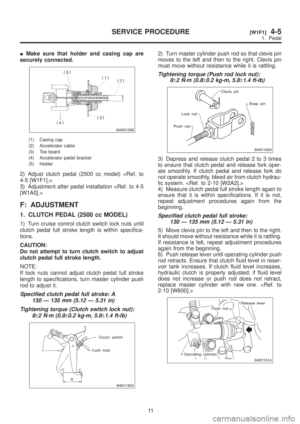
IMake sure that holder and casing cap are
securely connected.
B4M0159B
(1) Casing cap
(2) Accelerator cable
(3) Toe board
(4) Accelerator pedal bracket
(5) Holder
2) Adjust clutch pedal (2500 cc model)
3) Adjustment after pedal installation
F: ADJUSTMENT
1. CLUTCH PEDAL (2500 cc MODEL)
1) Turn cruise control clutch switch lock nuts until
clutch pedal full stroke length is within specifica-
tions.
CAUTION:
Do not attempt to turn clutch switch to adjust
clutch pedal full stroke length.
NOTE:
If lock nuts cannot adjust clutch pedal full stroke
length to specifications, turn master cylinder push
rod to adjust it.
Specified clutch pedal full stroke: A
130 Ð 135 mm (5.12 Ð 5.31 in)
Tightening torque (Clutch switch lock nut):
8
±2 N´m (0.8±0.2 kg-m, 5.8±1.4 ft-lb)
B4M1190A
2) Turn master cylinder push rod so that clevis pin
moves to the left and then to the right. Clevis pin
must move without resistance while it is rattling.
Tightening torque (Push rod lock nut):
8
±2 N´m (0.8±0.2 kg-m, 5.8±1.4 ft-lb)
B4M1189A
3) Depress and release clutch pedal 2 to 3 times
to ensure that clutch pedal and release fork oper-
ate smoothly. If clutch pedal and release fork do
not operate smoothly, bleed air from clutch hydrau-
lic system.
4) Measure clutch pedal full stroke length again to
ensure that it is within specifications. If it is not,
repeat adjustment procedures again from the
beginning.
Specified clutch pedal full stroke:
130 Ð 135 mm (5.12 Ð 5.31 in)
5) Move clevis pin to the left and then to the right.
It should move without resistance while it is rattling.
If resistance is felt, repeat adjustment procedures
again from the beginning.
6) Push release lever until operating cylinder push
rod retracts. Ensure that clutch fluid level in reser-
voir tank increases. If clutch fluid level increases,
hydraulic clutch is properly adjusted; if fluid level
does not increase or push rod does not retract,
replace master cylinder with new one.
B4M1191A
11
[W1F1]4-5SERVICE PROCEDURE
1. Pedal
Page 1238 of 1456
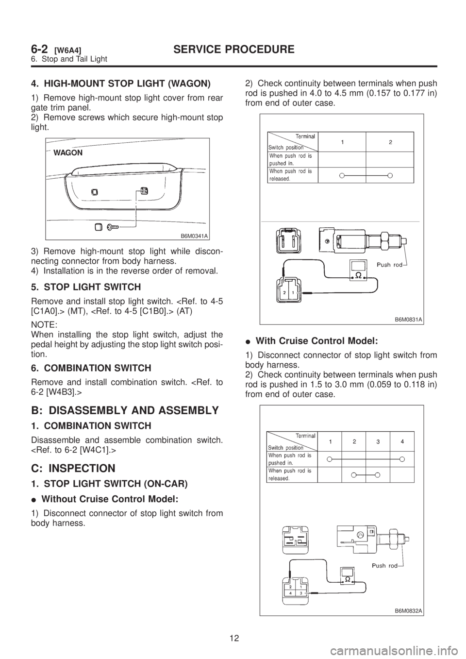
4. HIGH-MOUNT STOP LIGHT (WAGON)
1) Remove high-mount stop light cover from rear
gate trim panel.
2) Remove screws which secure high-mount stop
light.
B6M0341A
3) Remove high-mount stop light while discon-
necting connector from body harness.
4) Installation is in the reverse order of removal.
5. STOP LIGHT SWITCH
Remove and install stop light switch.
NOTE:
When installing the stop light switch, adjust the
pedal height by adjusting the stop light switch posi-
tion.
6. COMBINATION SWITCH
Remove and install combination switch.
B: DISASSEMBLY AND ASSEMBLY
1. COMBINATION SWITCH
Disassemble and assemble combination switch.
C: INSPECTION
1. STOP LIGHT SWITCH (ON-CAR)
IWithout Cruise Control Model:
1) Disconnect connector of stop light switch from
body harness.2) Check continuity between terminals when push
rod is pushed in 4.0 to 4.5 mm (0.157 to 0.177 in)
from end of outer case.
B6M0831A
IWith Cruise Control Model:
1) Disconnect connector of stop light switch from
body harness.
2) Check continuity between terminals when push
rod is pushed in 1.5 to 3.0 mm (0.059 to 0.118 in)
from end of outer case.
B6M0832A
12
6-2[W6A4]SERVICE PROCEDURE
6. Stop and Tail Light
Page 1271 of 1456
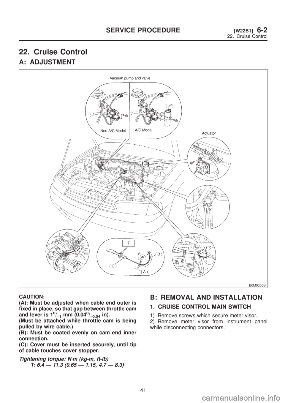
22. Cruise Control
A: ADJUSTMENT
B6M0356B
CAUTION:
(A): Must be adjusted when cable end outer is
fixed in place, so that gap between throttle cam
and lever is 1
0/þ1mm (0.040/þ0.04in).
(Must be attached while throttle cam is being
pulled by wire cable.)
(B): Must be coated evenly on cam end inner
connection.
(C): Cover must be inserted securely, until tip
of cable touches cover stopper.
Tightening torque: N´m (kg-m, ft-lb)
T: 6.4 Ð 11.3 (0.65 Ð 1.15, 4.7 Ð 8.3)
B: REMOVAL AND INSTALLATION
1. CRUISE CONTROL MAIN SWITCH
1) Remove screws which secure meter visor.
2) Remove meter visor from instrument panel
while disconnecting connectors.
41
[W22B1]6-2SERVICE PROCEDURE
22. Cruise Control
Page 1272 of 1456
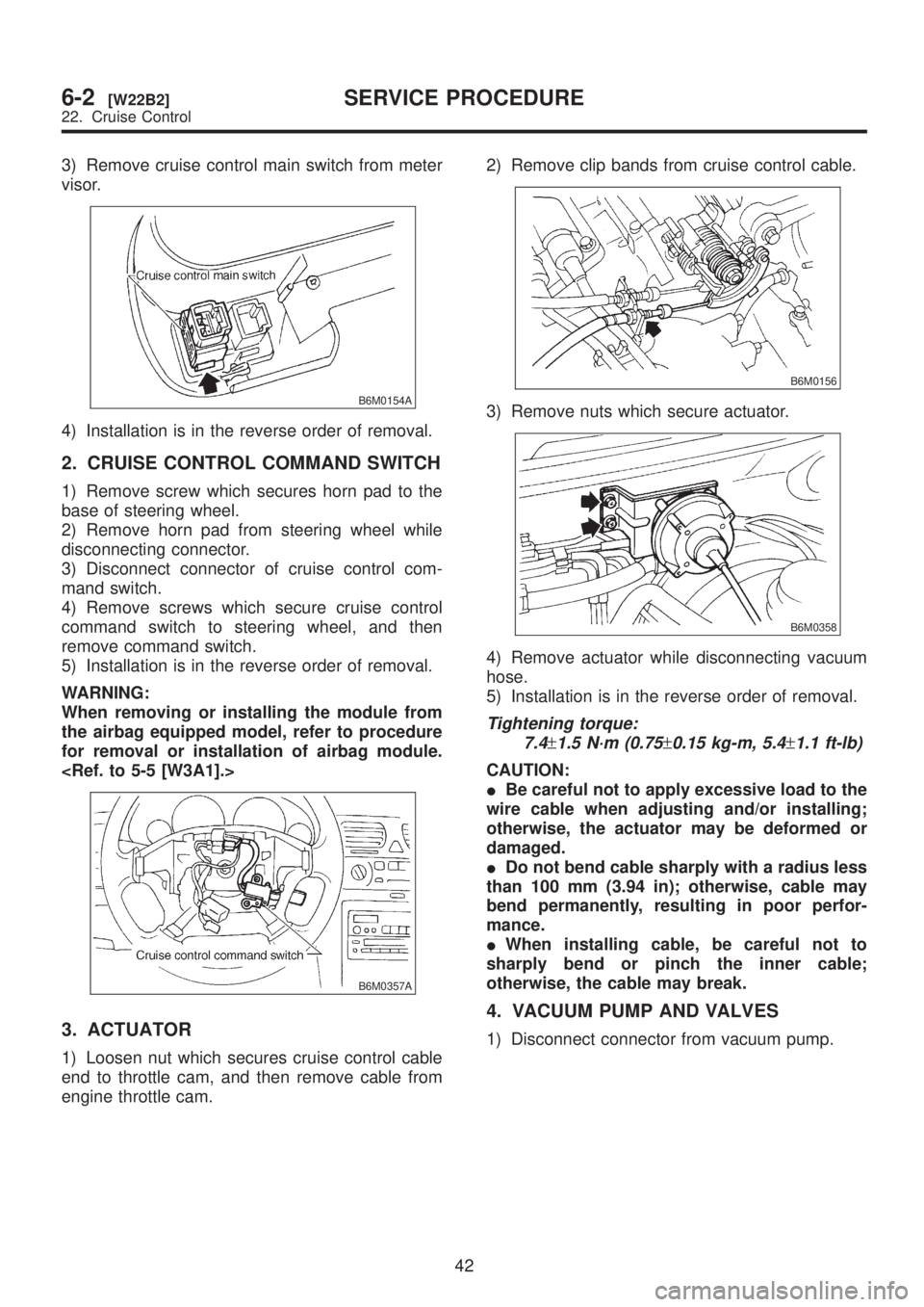
3) Remove cruise control main switch from meter
visor.
B6M0154A
4) Installation is in the reverse order of removal.
2. CRUISE CONTROL COMMAND SWITCH
1) Remove screw which secures horn pad to the
base of steering wheel.
2) Remove horn pad from steering wheel while
disconnecting connector.
3) Disconnect connector of cruise control com-
mand switch.
4) Remove screws which secure cruise control
command switch to steering wheel, and then
remove command switch.
5) Installation is in the reverse order of removal.
WARNING:
When removing or installing the module from
the airbag equipped model, refer to procedure
for removal or installation of airbag module.
B6M0357A
3. ACTUATOR
1) Loosen nut which secures cruise control cable
end to throttle cam, and then remove cable from
engine throttle cam.2) Remove clip bands from cruise control cable.
B6M0156
3) Remove nuts which secure actuator.
B6M0358
4) Remove actuator while disconnecting vacuum
hose.
5) Installation is in the reverse order of removal.
Tightening torque:
7.4
±1.5 N´m (0.75±0.15 kg-m, 5.4±1.1 ft-lb)
CAUTION:
IBe careful not to apply excessive load to the
wire cable when adjusting and/or installing;
otherwise, the actuator may be deformed or
damaged.
IDo not bend cable sharply with a radius less
than 100 mm (3.94 in); otherwise, cable may
bend permanently, resulting in poor perfor-
mance.
IWhen installing cable, be careful not to
sharply bend or pinch the inner cable;
otherwise, the cable may break.
4. VACUUM PUMP AND VALVES
1) Disconnect connector from vacuum pump.
42
6-2[W22B2]SERVICE PROCEDURE
22. Cruise Control
Page 1273 of 1456
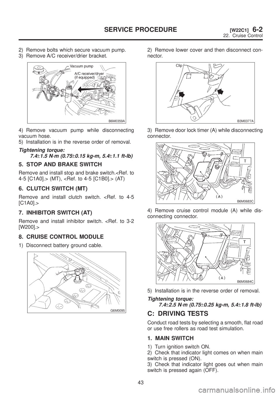
2) Remove bolts which secure vacuum pump.
3) Remove A/C receiver/drier bracket.
B6M0359A
4) Remove vacuum pump while disconnecting
vacuum hose.
5) Installation is in the reverse order of removal.
Tightening torque:
7.4
±1.5 N´m (0.75±0.15 kg-m, 5.4±1.1 ft-lb)
5. STOP AND BRAKE SWITCH
Remove and install stop and brake switch.
6. CLUTCH SWITCH (MT)
Remove and install clutch switch.
7. INHIBITOR SWITCH (AT)
Remove and install inhibitor switch.
8. CRUISE CONTROL MODULE
1) Disconnect battery ground cable.
G6M0095
2) Remove lower cover and then disconnect con-
nector.
B3M0377A
3) Remove door lock timer (A) while disconnecting
connector.
B6M0683C
4) Remove cruise control module (A) while dis-
connecting connector.
B6M0684C
5) Installation is in the reverse order of removal.
Tightening torque:
7.4
±2.5 N´m (0.75±0.25 kg-m, 5.4±1.8 ft-lb)
C: DRIVING TESTS
Conduct road tests by selecting a smooth, flat road
or use free rollers as road test simulation.
1. MAIN SWITCH
1) Turn ignition switch ON.
2) Check that indicator light comes on when main
switch is pressed (ON).
3) Check that indicator light goes out when main
switch is pressed again (OFF).
43
[W22C1]6-2SERVICE PROCEDURE
22. Cruise Control
Page 1274 of 1456
4) Turn ignition switch OFF with main switch ON
(which is indicated by illumination.).
5) Turn ignition switch ON again to ensure that
indicator light remains OFF.
2. COMMAND SWITCH
1) Check that command switch is properly set in
ªSET/COASTº, ªRESUME/ACCELº or ªCANCELº
mode.
2) Also check that command switch returns to the
original position when released.
3. CONSTANT SPEED TEST
1) Turn main switch ON.
2) Drive vehicle at speed greater than 40 km/h (25
MPH).
3) Press command switch to set in ªSET/COASTº
mode.
4) Ensure that vehicle is maintained at the speed
set when command switch was pressed.
4. ACCELERATION TEST
1) Set vehicle speed at speed greater than 40
km/h (25 MPH).
2) Ensure that vehicle continues to accelerate
while holding command switch in RESUME/
ACCEL mode, and that vehicle maintains that
optional speed when command switch is released.
5. DECELERATION TEST
1) Set vehicle speed at optional speed greater
than 40 km/h (25 MPH).
2) Ensure that vehicle continues to decelerate
while holding command switch in SET/COAST
mode, and that it maintains that optional speed
when command switch is released.
NOTE:
When vehicle speed reaches the lower speed limit
of 30 km/h (19 MPH) during deceleration, cruise
control will be released.
23. Security System
A: REMOVAL AND INSTALLATION
1. SECURITY CONTROL MODULE
1) Disconnect battery ground cable.
2) Remove radio.
3) Disconnect connector from security control
module and then remove security control module.
B6M0942
4) Installation is in the reverse order of removal.
NOTE:
ITo install the security control module, tighten
screws securely so that the screws do not come
loose.
IWhen installing a non-genuine radio, make sure
that the radio harness does not touch the security
control module.
B: INSPECTION
1. IMPACT SENSOR
Perform impact sensitivity test.
44
6-2[W22C2]SERVICE PROCEDURE
23. Security System
Page 1275 of 1456
4) Turn ignition switch OFF with main switch ON
(which is indicated by illumination.).
5) Turn ignition switch ON again to ensure that
indicator light remains OFF.
2. COMMAND SWITCH
1) Check that command switch is properly set in
ªSET/COASTº, ªRESUME/ACCELº or ªCANCELº
mode.
2) Also check that command switch returns to the
original position when released.
3. CONSTANT SPEED TEST
1) Turn main switch ON.
2) Drive vehicle at speed greater than 40 km/h (25
MPH).
3) Press command switch to set in ªSET/COASTº
mode.
4) Ensure that vehicle is maintained at the speed
set when command switch was pressed.
4. ACCELERATION TEST
1) Set vehicle speed at speed greater than 40
km/h (25 MPH).
2) Ensure that vehicle continues to accelerate
while holding command switch in RESUME/
ACCEL mode, and that vehicle maintains that
optional speed when command switch is released.
5. DECELERATION TEST
1) Set vehicle speed at optional speed greater
than 40 km/h (25 MPH).
2) Ensure that vehicle continues to decelerate
while holding command switch in SET/COAST
mode, and that it maintains that optional speed
when command switch is released.
NOTE:
When vehicle speed reaches the lower speed limit
of 30 km/h (19 MPH) during deceleration, cruise
control will be released.
23. Security System
A: REMOVAL AND INSTALLATION
1. SECURITY CONTROL MODULE
1) Disconnect battery ground cable.
2) Remove radio.
3) Disconnect connector from security control
module and then remove security control module.
B6M0942
4) Installation is in the reverse order of removal.
NOTE:
ITo install the security control module, tighten
screws securely so that the screws do not come
loose.
IWhen installing a non-genuine radio, make sure
that the radio harness does not touch the security
control module.
B: INSPECTION
1. IMPACT SENSOR
Perform impact sensitivity test.
44
6-2[W22C2]SERVICE PROCEDURE
23. Security System
Page 1296 of 1456
No. Load
MB-1Fuse holder (Rear power supply & seat
heater)
MB-2 Power window circuit breaker
MB-3Data link connector
Engine control module
Fuel pump relay
Main relay
MB-4 A/C relay holder
MB-6 Headlight LH
MB-7Daytime running light control module
Diode (Lighting)
Diode (Security)
Lighting switch
MB-8Combination meter
Front fog light switch
Headlight RH
Front fog light relay
MB-9Door lock timer
Headlight alarm relay
Radio
Security control module
Security indicator light
Spot light
Room light
Step light
Combination meter
Luggage room light
Trailer connector
Trunk room light
MB-10 A/C relay holder
SBF-6ABS relay box
TCS motor relay
SBF-7 TCS valve relay
ALT-1Combination meter
Daytime running light control module
Diode (TCS)
IG Headlight alarm relay
STCruise control module
Engine control module
Inhibitor switch (AT)
Interrupt relay (with security)
Starter interlock relay (MT)
FB-1Front washer motor
Rear washer motor
FB-2Engine control module
Main fan relay 1
FB-3Sub fan relay 2
Sub fan motor
FB-4Engine control module
Fuel pump relay
Ignition coil
Transmission control module
FB-5 ABS relay box
FB-6Side marker light LH
Side marker light RH
FB-7Door lock timer
Keyless entry control moduleNo. Load
FB-8 Wiper deicer relay
FB-9 Hazard switch
FB-10AT shift lock control module
Key warning switch
Power antenna
FB-11 Radio
FB-12 Front accessory power supply
FB-13Mirror heater
Rear power supply relay
Remote control rearview mirror switch
Security control module
Vanity mirror illumination light
FB-14AT shift lock control module
Combination switch
Front wiper motor
Rear wiper motor
Rear wiper relay
FB-15ABS/TCS control module
Transmission control module
FB-16Rear defogger
Rear defogger condenser
Rear defogger switch
FB-17 Rear defogger timer
FB-18AT shift lock control module
Back-up light switch (MT)
Inhibitor switch (AT)
FB-19 Hazard switch
FB-20A/C switch
Combination meter
Mode control panel
Rear defogger timer
TCS off switch
FB-22Blower motor relay
Check connector
Daytime running light control module
Daytime running light relay
FRESH/RECIRC actuator
Hi-beam relay
Keyless entry control module
Power window and sunroof relay
Seat belt timer
Security control module
Vehicle speed sensor (MT)
Wiper deicer relay
Wiper deicer timer
FB-23 Airbag control module
FB-24 Airbag control module
FB-25 Lighting switch
FB-26Keyless entry control module
Parking switch
FB-27Keyless entry control module
Parking switch
Security control module
FB-28 Illumination light
FB-29 Illumination light
16
6-3[D6A1]WIRING DIAGRAM
6. Wiring Diagram