Page 311 of 1456
15) Install fuel protector RH. (RHD model only)
B2M2755
16) Install power steering pump on bracket.
(1) Tighten bolts which install power steering
pump on bracket.
Tightening torque:
20.1
±2.5 N´m (2.05±0.25 kg-m, 14.8±1.8
ft-lb)
B2M2310
(2) Install power steering pipe brackets on the
right side of intake manifold.
B2M2309
(3) Install power steering pump drive V-belt.
B2M2308
(4) Adjust V-belt.
(5) Install V-belt covers.
B2M2307
(6) Install resonator chamber.
Tightening torque:
7.4
±2.0 N´m (0.75±0.2 kg-m, 5.4±1.4 ft-lb)
B2M2306
17) Connect accelerator cable (A).
18) Connect cruise control cable (B). (With cruise
control models)
B2M2295A
50
2-7[W4D1]SERVICE PROCEDURE
4. Intake Manifold
Page 444 of 1456
(2) Disconnect the following cables.
H2M2433D
(1) Accelerator cable
(2) Cruise control cable (With cruise
control vehicles)
(3) Clutch return spring (Without hill
holder vehicles)
(4) Clutch cable (2200 cc MT
vehicles)
12
2-11[W1B0]SERVICE PROCEDURE
1. Engine
Page 450 of 1456

7) Install canister and bracket.
(1) Install power stering pump on bracket, and
tighten bolts.
Tightening torque:
39
±10 N´m (4.0±1.0 kg-m, 29±7 ft-lb)
S2M0086
(2) Install power steering pipe bracket on right
side intake manifold, and install spark plug
codes.
B2M2309
(3) Install front side V-belt, and adjust it.
G2M0286
8) Tighten nuts which hold lower side of transmis-
sion to engine.
Tightening torque:
50
±4 N´m (5.1±0.4 kg-m, 36.9±2.9 ft-lb)
B2M2790
9) Tighten nuts which install front cushion rubber
onto crossmember.
Tightening torque:
69
±15 N´m (7.0±1.5 kg-m, 51±11 ft-lb)
CAUTION:
Be sure to tighten front cushion rubber mount-
ing bolts in the innermost elliptical hole in the
front crossmember.
G2M0303
10) Install front exhaust pipe and center exhaust
pipe.
11) Connect the following hoses.
(1) Fuel delivery hose, return hose and evapo-
ration hose
(2) Heater inlet and outlet hoses
(3) Brake booster vacuum hose
12) Connect the following connectors.
(1) Engine ground terminal
(2) Engine harness connectors
(3) Front oxygen sensor connector
(4) Rear oxygen sensor connector (California
spec. vehicles)
(5) Alternator connector and terminal
(6) A/C compressor connectors (With A/C)
13) Connect the following cables.
(1) Accelerator cable
(2) Cruise control cables (With cruise control)
(3) Clutch cable (2200 cc MT vehicles)
18
2-11[W1C0]SERVICE PROCEDURE
1. Engine
Page 463 of 1456

18) Install ATF level gauge. (AT vehicles)
S2M0214
19) Connect the following connectors.
(1) Transmission harness connectors (AT
vehicles)
(2) Transmission ground terminal
(3) Front oxygen sensor connector
(4) Rear oxygen sensor connector (California
spec. vehicles)
(5) Neutral position switch connector (MT
vehicles)
(6) Back-up light switch connector (MT
vehicles)
20) Connect the following cables.
(1) Cruise control cable
(With cruise control vehicles)
(2) Clutch cable (2200 cc MT vehicles)
21) Install return spring.
(Without hill holder vehicles)
22) Install starter.
(1) Install starter onto transmission case, and
connect connectors and terminals.
(2) Tighten bolt and nut which install starter
onto transmission.
Tightening torque:
40
±4 N´m (4.1±0.4 kg-m, 29.7±2.9 ft-lb)
G2M0309
23) Install chamber stay.
IMT vehicles
S2M0210
IAT vehicles
S6M0023
24) Install air intake duct and chamber. (Except
2200 cc California spec. vehicles)
[W1A0].>
25) Install air intake duct with air cleaner case.
(2200 cc California spec. vehicles)
[W1A0].> and
26) Connect battery ground cable.
27) Fill ATF and differential gear oil. (AT vehicles)
28) Check selector lever operation. (AT vehicles)
29) Take off vehicle from lift arms.
30) Check the vehicle on road tester. (AT vehicles)
31
[W2C0]2-11SERVICE PROCEDURE
2. Transmission
Page 805 of 1456

CAUTION:
Insert roll connector guide pin into guide hole
on lower end of surface of steering wheel to
prevent damage.
Draw out airbag system connector, horn con-
nector and cruise control connectors from
guide hole of steering wheel lower end. (with
airbag model)
8) Install airbag module to steering wheel. (with
airbag model)
WARNING:
Always refer to 5-5 Supplemental Restraint
System before performing the service opera-
tion. 3. Steering Gearbox (Power
Steering System) [LHD model]
A: REMOVAL
NOTE:
For disassembly and assembly of gearbox unit,
refer to section Control Valve (Power Steering
Gearbox) [LHD model]. and
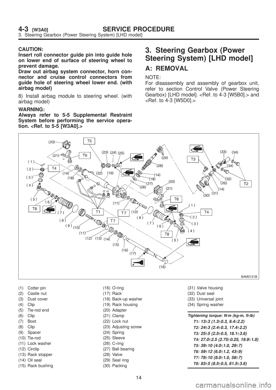
B4M0131B
(1) Cotter pin
(2) Castle nut
(3) Dust cover
(4) Clip
(5) Tie-rod end
(6) Clip
(7) Boot
(8) Clip
(9) Spacer
(10) Tie-rod
(11) Lock washer
(12) Circlip
(13) Rack stopper
(14) Oil seal
(15) Rack bushing(16) O-ring
(17) Rack
(18) Back-up washer
(19) Rack housing
(20) Adapter
(21) Clamp
(22) Lock nut
(23) Adjusting screw
(24) Spring
(25) Sleeve
(26) C-ring
(27) Ball bearing
(28) Valve
(29) Seal ring
(30) Packing(31) Valve housing
(32) Dust seal
(33) Universal joint
(34) Spring washer
Tightening torque: N´m (kg-m, ft-lb)
T1:
13±3 (1.3±0.3, 9.4±2.2)
T2:24±3 (2.4±0.3, 17.4±2.2)
T3:25±5 (2.5±0.5, 18.1±3.6)
T4:27.0±2.5 (2.75±0.25, 19.9±1.8)
T5:39±10 (4.0±1.0, 29±7)
T6:59±12 (6.0±1.2, 43±9)
T7:78±10 (8.0±1.0, 58±7)
T8:83±5 (8.5±0.5, 61.5±3.6)
14
4-3[W3A0]SERVICE PROCEDURE
3. Steering Gearbox (Power Steering System) [LHD model]
Page 806 of 1456

CAUTION:
Insert roll connector guide pin into guide hole
on lower end of surface of steering wheel to
prevent damage.
Draw out airbag system connector, horn con-
nector and cruise control connectors from
guide hole of steering wheel lower end. (with
airbag model)
8) Install airbag module to steering wheel. (with
airbag model)
WARNING:
Always refer to 5-5 Supplemental Restraint
System before performing the service opera-
tion. 3. Steering Gearbox (Power
Steering System) [LHD model]
A: REMOVAL
NOTE:
For disassembly and assembly of gearbox unit,
refer to section Control Valve (Power Steering
Gearbox) [LHD model]. and
B4M0131B
(1) Cotter pin
(2) Castle nut
(3) Dust cover
(4) Clip
(5) Tie-rod end
(6) Clip
(7) Boot
(8) Clip
(9) Spacer
(10) Tie-rod
(11) Lock washer
(12) Circlip
(13) Rack stopper
(14) Oil seal
(15) Rack bushing(16) O-ring
(17) Rack
(18) Back-up washer
(19) Rack housing
(20) Adapter
(21) Clamp
(22) Lock nut
(23) Adjusting screw
(24) Spring
(25) Sleeve
(26) C-ring
(27) Ball bearing
(28) Valve
(29) Seal ring
(30) Packing(31) Valve housing
(32) Dust seal
(33) Universal joint
(34) Spring washer
Tightening torque: N´m (kg-m, ft-lb)
T1:
13±3 (1.3±0.3, 9.4±2.2)
T2:24±3 (2.4±0.3, 17.4±2.2)
T3:25±5 (2.5±0.5, 18.1±3.6)
T4:27.0±2.5 (2.75±0.25, 19.9±1.8)
T5:39±10 (4.0±1.0, 29±7)
T6:59±12 (6.0±1.2, 43±9)
T7:78±10 (8.0±1.0, 58±7)
T8:83±5 (8.5±0.5, 61.5±3.6)
14
4-3[W3A0]SERVICE PROCEDURE
3. Steering Gearbox (Power Steering System) [LHD model]
Page 849 of 1456

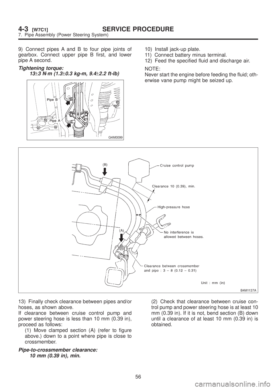
9) Connect pipes A and B to four pipe joints of
gearbox. Connect upper pipe B first, and lower
pipe A second.
Tightening torque:
13
±3 N´m (1.3±0.3 kg-m, 9.4±2.2 ft-lb)
G4M0099
10) Install jack-up plate.
11) Connect battery minus terminal.
12) Feed the specified fluid and discharge air.
NOTE:
Never start the engine before feeding the fluid; oth-
erwise vane pump might be seized up.
B4M1137A
13) Finally check clearance between pipes and/or
hoses, as shown above.
If clearance between cruise control pump and
power steering hose is less than 10 mm (0.39 in),
proceed as follows:
(1) Move clamped section (A) (refer to figure
above.) down to a point where pipe is close to
crossmember.
Pipe-to-crossmember clearance:
10 mm (0.39 in), min.
(2) Check that clearance between cruise con-
trol pump and power steering hose is at least 10
mm (0.39 in). If it is not, bend section (B) down
until a clearance of at least 10 mm (0.39 in) is
obtained.
56
4-3[W7C1]SERVICE PROCEDURE
7. Pipe Assembly (Power Steering System)
Page 870 of 1456

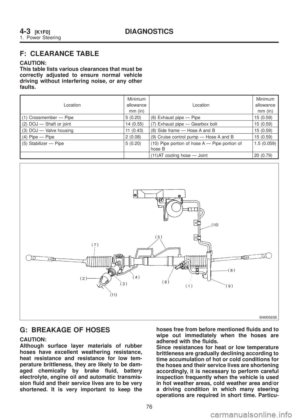
F: CLEARANCE TABLE
CAUTION:
This table lists various clearances that must be
correctly adjusted to ensure normal vehicle
driving without interfering noise, or any other
faults.
LocationMinimum
allowance
mm (in)LocationMinimum
allowance
mm (in)
(1) Crossmember Ð Pipe 5 (0.20) (6) Exhaust pipe Ð Pipe 15 (0.59)
(2) DOJ Ð Shaft or joint 14 (0.55) (7) Exhaust pipe Ð Gearbox bolt 15 (0.59)
(3) DOJ Ð Valve housing 11 (0.43) (8) Side frame Ð Hose A and B 15 (0.59)
(4) Pipe Ð Pipe 2 (0.08) (9) Cruise control pump Ð Hose A and B 15 (0.59)
(5) Stabilizer Ð Pipe 5 (0.20) (10) Pipe portion of hose A Ð Pipe portion of
hose B1.5 (0.059)
(11)AT cooling hose Ð Joint 20 (0.79)
B4M0565B
G: BREAKAGE OF HOSES
CAUTION:
Although surface layer materials of rubber
hoses have excellent weathering resistance,
heat resistance and resistance for low tem-
perature brittleness, they are likely to be dam-
aged chemically by brake fluid, battery
electrolyte, engine oil and automatic transmis-
sion fluid and their service lives are to be very
shortened. It is very important to keep thehoses free from before mentioned fluids and to
wipe out immediately when the hoses are
adhered with the fluids.
Since resistances for heat or low temperature
brittleness are gradually declining according to
time accumulation of hot or cold conditions for
the hoses and their service lives are shortening
accordingly, it is necessary to perform careful
inspection frequently when the vehicle is used
in hot weather areas, cold weather area and/or
a driving condition in which many steering
operations are required in short time. Particu-
76
4-3[K1F0]DIAGNOSTICS
1. Power Steering