Page 1089 of 1456
2. WAGON FRONT (OUTBACK)
1) Alignment of height between sunroof panel and
roof panel
Loosen sunroof panel installation bolts and nuts
then adjust height by adding (Max: two pieces) and
extracting (Max: one piece) shim(s) (Standard: one
piece) between sunroof panel hinge and body.
Difference in height between sunroof panel
and roof panel:
0
±1.0 mm (0±0.039 in)
B5M0486A
2) Alignment of partition clearance
Loosen sunroof panel installation bolts and nuts
then move glass to either side to adjust front, rear,
right, and left side partitions.
Partition clearance:
1
±1.0 mm (0.04±0.039 in)
B5M0487A
17. Undercover
A: REMOVAL AND INSTALLATION
1) Remove undercover mounting bolts.
B5M0412A
2) Installation is in the reverse order of removal.
NOTE:
Undercover is bolted along with mud guard.
61
[W17A0]5-1SERVICE PROCEDURE
17. Undercover
Page 1090 of 1456
2. WAGON FRONT (OUTBACK)
1) Alignment of height between sunroof panel and
roof panel
Loosen sunroof panel installation bolts and nuts
then adjust height by adding (Max: two pieces) and
extracting (Max: one piece) shim(s) (Standard: one
piece) between sunroof panel hinge and body.
Difference in height between sunroof panel
and roof panel:
0
±1.0 mm (0±0.039 in)
B5M0486A
2) Alignment of partition clearance
Loosen sunroof panel installation bolts and nuts
then move glass to either side to adjust front, rear,
right, and left side partitions.
Partition clearance:
1
±1.0 mm (0.04±0.039 in)
B5M0487A
17. Undercover
A: REMOVAL AND INSTALLATION
1) Remove undercover mounting bolts.
B5M0412A
2) Installation is in the reverse order of removal.
NOTE:
Undercover is bolted along with mud guard.
61
[W17A0]5-1SERVICE PROCEDURE
17. Undercover
Page 1091 of 1456
18. Rear Spoiler
A: REMOVAL AND INSTALLATION
1) Open trunk lid.
2) Disconnect high-mount stop light connector
located inside the trunk lid.
3) Remove rubber caps.
B5M0413
4) Remove rear spoiler mounting nuts.
CAUTION:
When removing nuts, be careful not to drop
them inside rear gate.
B5M0414
5) Installation is in the reverse order of removal.
Tightening torque:
7.4
±2.0 N´m (0.75±0.2 kg-m, 5.4±1.4 ft-lb)
19. Roof Spoiler
A: REMOVAL AND INSTALLATION
1) Open rear gate and remove rear gate trim
upper and side.
B5M0305
2) Remove high-mount stop light.
[W6A4].>
3) Remove plastic caps and harness covers.
B5M0415A
4) Remove roof spoiler mounting nuts.
CAUTION:
IWhen removing nuts, be careful not to drop
them inside rear gate.
IBe careful since two-sided tape is placed
between roof spoiler and body panel.
B5M0306
5) Installation is in the reverse order of removal.
Tightening torque:
7.4
±2.0 N´m (0.75±0.2 kg-m, 5.4±1.4 ft-lb)
62
5-1[W18A0]SERVICE PROCEDURE
18. Rear Spoiler
Page 1092 of 1456
18. Rear Spoiler
A: REMOVAL AND INSTALLATION
1) Open trunk lid.
2) Disconnect high-mount stop light connector
located inside the trunk lid.
3) Remove rubber caps.
B5M0413
4) Remove rear spoiler mounting nuts.
CAUTION:
When removing nuts, be careful not to drop
them inside rear gate.
B5M0414
5) Installation is in the reverse order of removal.
Tightening torque:
7.4
±2.0 N´m (0.75±0.2 kg-m, 5.4±1.4 ft-lb)
19. Roof Spoiler
A: REMOVAL AND INSTALLATION
1) Open rear gate and remove rear gate trim
upper and side.
B5M0305
2) Remove high-mount stop light.
[W6A4].>
3) Remove plastic caps and harness covers.
B5M0415A
4) Remove roof spoiler mounting nuts.
CAUTION:
IWhen removing nuts, be careful not to drop
them inside rear gate.
IBe careful since two-sided tape is placed
between roof spoiler and body panel.
B5M0306
5) Installation is in the reverse order of removal.
Tightening torque:
7.4
±2.0 N´m (0.75±0.2 kg-m, 5.4±1.4 ft-lb)
62
5-1[W18A0]SERVICE PROCEDURE
18. Rear Spoiler
Page 1097 of 1456

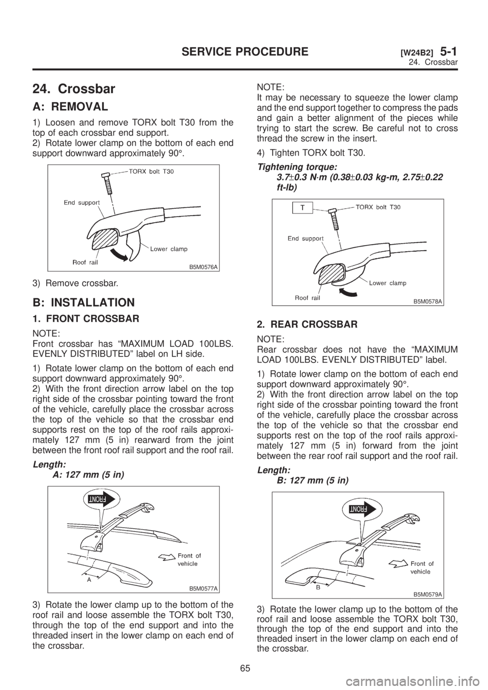
24. Crossbar
A: REMOVAL
1) Loosen and remove TORX bolt T30 from the
top of each crossbar end support.
2) Rotate lower clamp on the bottom of each end
support downward approximately 90É.
B5M0576A
3) Remove crossbar.
B: INSTALLATION
1. FRONT CROSSBAR
NOTE:
Front crossbar has ªMAXIMUM LOAD 100LBS.
EVENLY DISTRIBUTEDº label on LH side.
1) Rotate lower clamp on the bottom of each end
support downward approximately 90É.
2) With the front direction arrow label on the top
right side of the crossbar pointing toward the front
of the vehicle, carefully place the crossbar across
the top of the vehicle so that the crossbar end
supports rest on the top of the roof rails approxi-
mately 127 mm (5 in) rearward from the joint
between the front roof rail support and the roof rail.
Length:
A: 127 mm (5 in)
B5M0577A
3) Rotate the lower clamp up to the bottom of the
roof rail and loose assemble the TORX bolt T30,
through the top of the end support and into the
threaded insert in the lower clamp on each end of
the crossbar.NOTE:
It may be necessary to squeeze the lower clamp
and the end support together to compress the pads
and gain a better alignment of the pieces while
trying to start the screw. Be careful not to cross
thread the screw in the insert.
4) Tighten TORX bolt T30.
Tightening torque:
3.7
±0.3 N´m (0.38±0.03 kg-m, 2.75±0.22
ft-lb)
B5M0578A
2. REAR CROSSBAR
NOTE:
Rear crossbar does not have the ªMAXIMUM
LOAD 100LBS. EVENLY DISTRIBUTEDº label.
1) Rotate lower clamp on the bottom of each end
support downward approximately 90É.
2) With the front direction arrow label on the top
right side of the crossbar pointing toward the front
of the vehicle, carefully place the crossbar across
the top of the vehicle so that the crossbar end
supports rest on the top of the roof rails approxi-
mately 127 mm (5 in) forward from the joint
between the rear roof rail support and the roof rail.
Length:
B: 127 mm (5 in)
B5M0579A
3) Rotate the lower clamp up to the bottom of the
roof rail and loose assemble the TORX bolt T30,
through the top of the end support and into the
threaded insert in the lower clamp on each end of
the crossbar.
65
[W24B2]5-1SERVICE PROCEDURE
24. Crossbar
Page 1099 of 1456

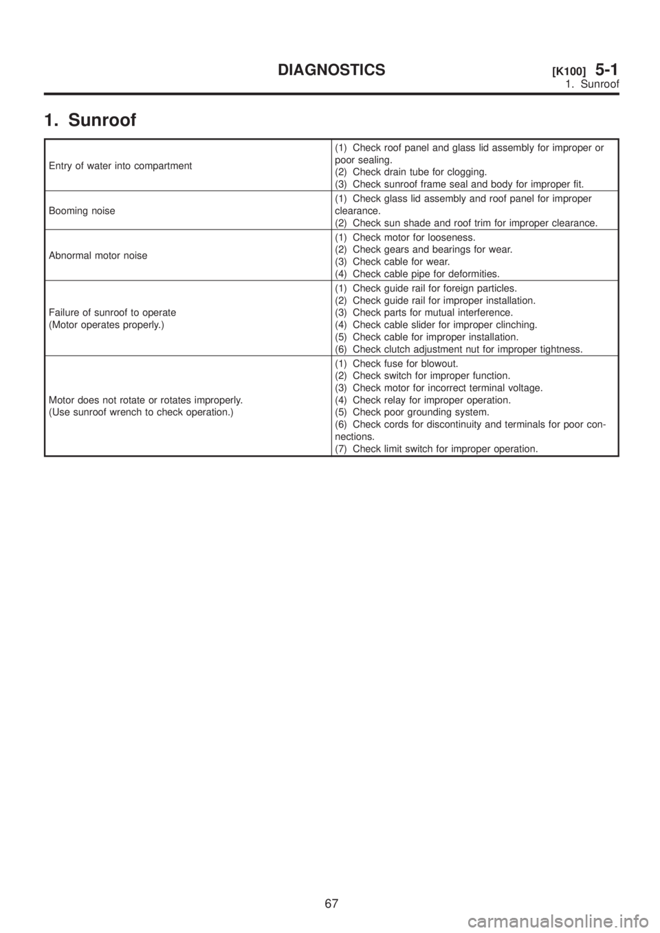
1. Sunroof
Entry of water into compartment(1) Check roof panel and glass lid assembly for improper or
poor sealing.
(2) Check drain tube for clogging.
(3) Check sunroof frame seal and body for improper fit.
Booming noise(1) Check glass lid assembly and roof panel for improper
clearance.
(2) Check sun shade and roof trim for improper clearance.
Abnormal motor noise(1) Check motor for looseness.
(2) Check gears and bearings for wear.
(3) Check cable for wear.
(4) Check cable pipe for deformities.
Failure of sunroof to operate
(Motor operates properly.)(1) Check guide rail for foreign particles.
(2) Check guide rail for improper installation.
(3) Check parts for mutual interference.
(4) Check cable slider for improper clinching.
(5) Check cable for improper installation.
(6) Check clutch adjustment nut for improper tightness.
Motor does not rotate or rotates improperly.
(Use sunroof wrench to check operation.)(1) Check fuse for blowout.
(2) Check switch for improper function.
(3) Check motor for incorrect terminal voltage.
(4) Check relay for improper operation.
(5) Check poor grounding system.
(6) Check cords for discontinuity and terminals for poor con-
nections.
(7) Check limit switch for improper operation.
67
[K100]5-1DIAGNOSTICS
1. Sunroof
Page 1122 of 1456

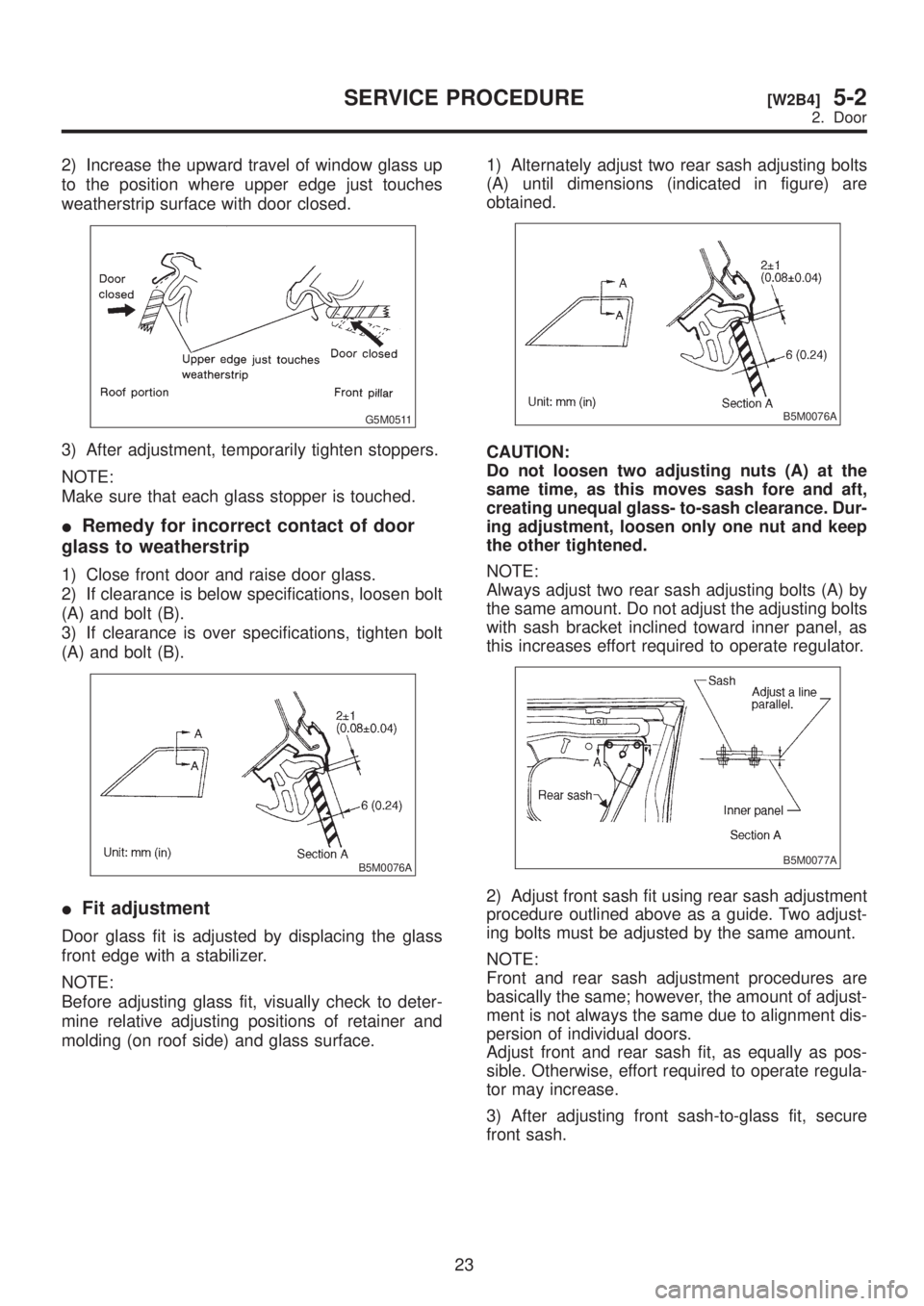
2) Increase the upward travel of window glass up
to the position where upper edge just touches
weatherstrip surface with door closed.
G5M0511
3) After adjustment, temporarily tighten stoppers.
NOTE:
Make sure that each glass stopper is touched.
IRemedy for incorrect contact of door
glass to weatherstrip
1) Close front door and raise door glass.
2) If clearance is below specifications, loosen bolt
(A) and bolt (B).
3) If clearance is over specifications, tighten bolt
(A) and bolt (B).
B5M0076A
IFit adjustment
Door glass fit is adjusted by displacing the glass
front edge with a stabilizer.
NOTE:
Before adjusting glass fit, visually check to deter-
mine relative adjusting positions of retainer and
molding (on roof side) and glass surface.1) Alternately adjust two rear sash adjusting bolts
(A) until dimensions (indicated in figure) are
obtained.
B5M0076A
CAUTION:
Do not loosen two adjusting nuts (A) at the
same time, as this moves sash fore and aft,
creating unequal glass- to-sash clearance. Dur-
ing adjustment, loosen only one nut and keep
the other tightened.
NOTE:
Always adjust two rear sash adjusting bolts (A) by
the same amount. Do not adjust the adjusting bolts
with sash bracket inclined toward inner panel, as
this increases effort required to operate regulator.
B5M0077A
2) Adjust front sash fit using rear sash adjustment
procedure outlined above as a guide. Two adjust-
ing bolts must be adjusted by the same amount.
NOTE:
Front and rear sash adjustment procedures are
basically the same; however, the amount of adjust-
ment is not always the same due to alignment dis-
persion of individual doors.
Adjust front and rear sash fit, as equally as pos-
sible. Otherwise, effort required to operate regula-
tor may increase.
3) After adjusting front sash-to-glass fit, secure
front sash.
23
[W2B4]5-2SERVICE PROCEDURE
2. Door
Page 1157 of 1456

7) Remove rear quarter pillar lower trim.
B5M0045
8) Installation is in the reverse order of removal.
CAUTION:
Be careful not to ride trim panel over harness,
insulators, etc.
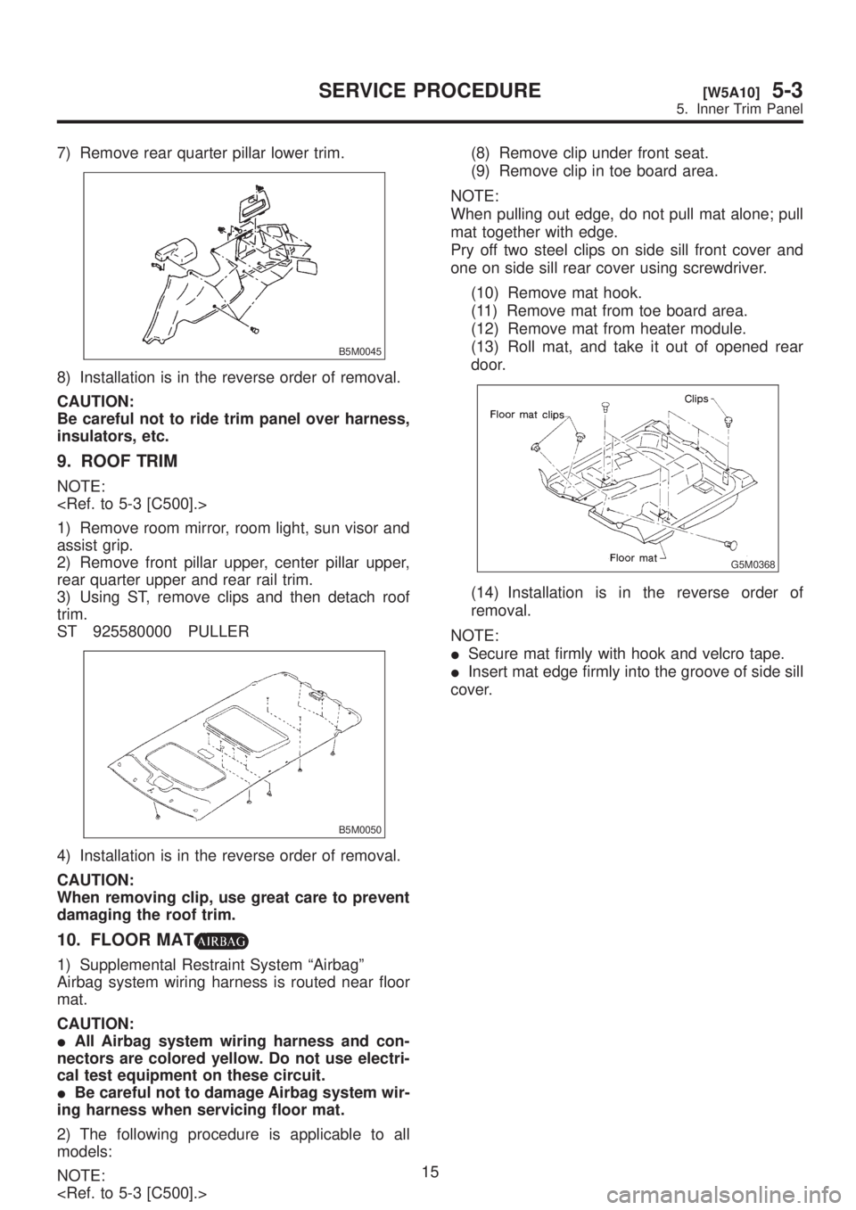
9. ROOF TRIM
NOTE:
1) Remove room mirror, room light, sun visor and
assist grip.
2) Remove front pillar upper, center pillar upper,
rear quarter upper and rear rail trim.
3) Using ST, remove clips and then detach roof
trim.
ST 925580000 PULLER
B5M0050
4) Installation is in the reverse order of removal.
CAUTION:
When removing clip, use great care to prevent
damaging the roof trim.
10. FLOOR MAT
1) Supplemental Restraint System ªAirbagº
Airbag system wiring harness is routed near floor
mat.
CAUTION:
IAll Airbag system wiring harness and con-
nectors are colored yellow. Do not use electri-
cal test equipment on these circuit.
IBe careful not to damage Airbag system wir-
ing harness when servicing floor mat.
2) The following procedure is applicable to all
models:
NOTE:
(8) Remove clip under front seat.
(9) Remove clip in toe board area.
NOTE:
When pulling out edge, do not pull mat alone; pull
mat together with edge.
Pry off two steel clips on side sill front cover and
one on side sill rear cover using screwdriver.
(10) Remove mat hook.
(11) Remove mat from toe board area.
(12) Remove mat from heater module.
(13) Roll mat, and take it out of opened rear
door.
G5M0368
(14) Installation is in the reverse order of
removal.
NOTE:
ISecure mat firmly with hook and velcro tape.
IInsert mat edge firmly into the groove of side sill
cover.
15
[W5A10]5-3SERVICE PROCEDURE
5. Inner Trim Panel