1999 SUBARU LEGACY power steering fluid
[x] Cancel search: power steering fluidPage 831 of 1456
NOTE:
Apply specified power steering fluid to outer diam-
eter surface of input shaft and outer surface of
valve body seal ring, and pay special attention not
to damage seal when inserting pinion and valve
assembly.
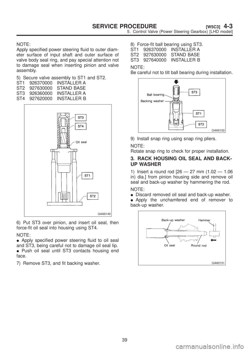
5) Secure valve assembly to ST1 and ST2.
ST1 926370000 INSTALLER A
ST2 927630000 STAND BASE
ST3 926360000 INSTALLER A
ST4 927620000 INSTALLER B
G4M0149
6) Put ST3 over pinion, and insert oil seal, then
force-fit oil seal into housing using ST4.
NOTE:
IApply specified power steering fluid to oil seal
and ST3, being careful not to damage oil seal lip.
IPush oil seal until ST3 contacts housing end
face.
7) Remove ST3, and fit backing washer.8) Force-fit ball bearing using ST3.
ST1 926370000 INSTALLER A
ST2 927630000 STAND BASE
ST3 927640000 INSTALLER B
NOTE:
Be careful not to tilt ball bearing during installation.
G4M0150
9) Install snap ring using snap ring pliers.
NOTE:
Rotate snap ring to check for proper installation.
3. RACK HOUSING OIL SEAL AND BACK-
UP WASHER
1) Insert a round rod [26 Ð 27 mm (1.02 Ð 1.06
in) dia.] from pinion housing side and remove oil
seal and back-up washer by hammering the rod.
NOTE:
IDiscard removed oil seal and back-up washer.
IApply the unchamfered end of remover to
back-up washer.
G4M0151
39
[W5C3]4-3SERVICE PROCEDURE
5. Control Valve (Power Steering Gearbox) [LHD model]
Page 832 of 1456
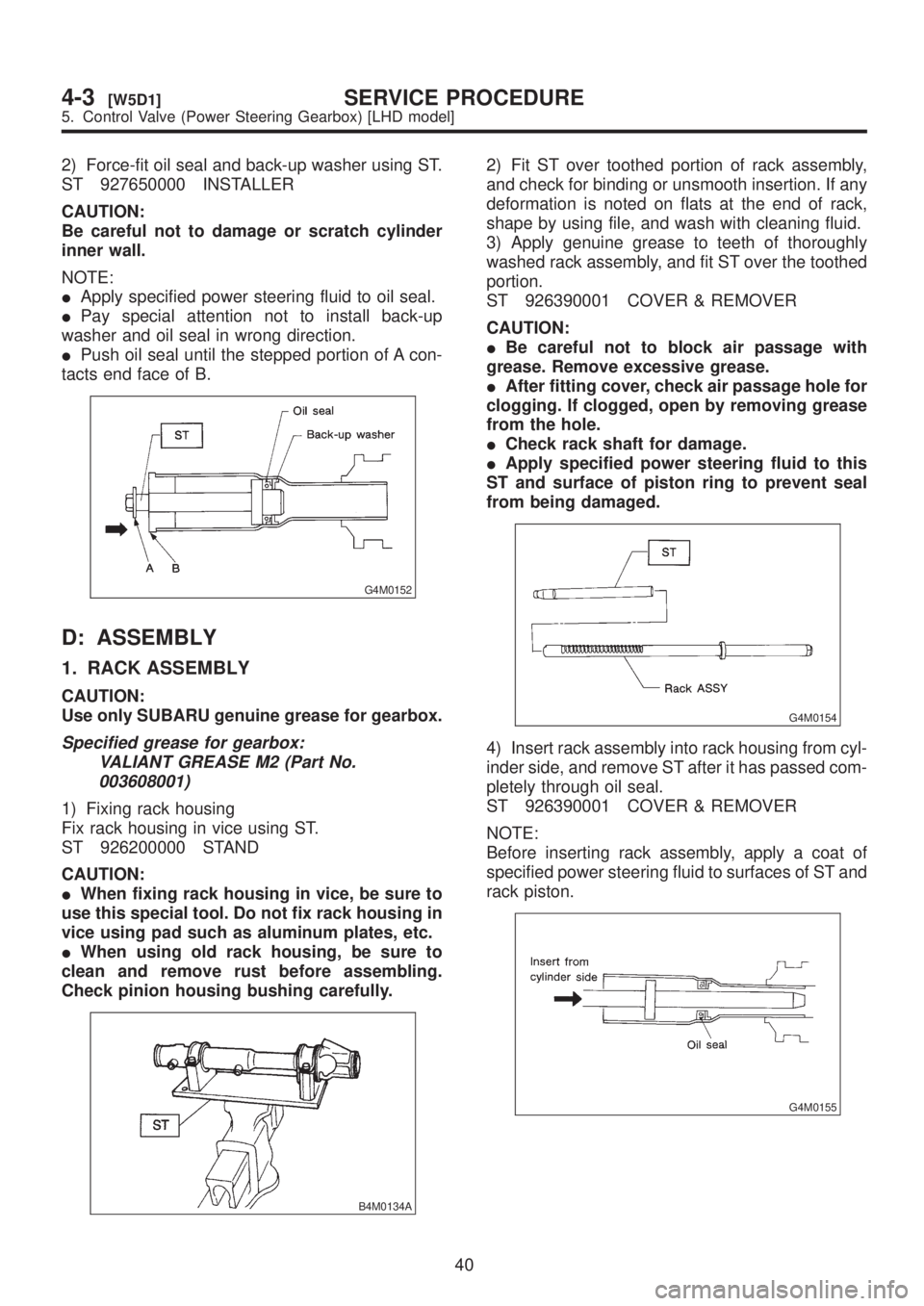
2) Force-fit oil seal and back-up washer using ST.
ST 927650000 INSTALLER
CAUTION:
Be careful not to damage or scratch cylinder
inner wall.
NOTE:
IApply specified power steering fluid to oil seal.
IPay special attention not to install back-up
washer and oil seal in wrong direction.
IPush oil seal until the stepped portion of A con-
tacts end face of B.
G4M0152
D: ASSEMBLY
1. RACK ASSEMBLY
CAUTION:
Use only SUBARU genuine grease for gearbox.
Specified grease for gearbox:
VALIANT GREASE M2 (Part No.
003608001)
1) Fixing rack housing
Fix rack housing in vice using ST.
ST 926200000 STAND
CAUTION:
IWhen fixing rack housing in vice, be sure to
use this special tool. Do not fix rack housing in
vice using pad such as aluminum plates, etc.
IWhen using old rack housing, be sure to
clean and remove rust before assembling.
Check pinion housing bushing carefully.
B4M0134A
2) Fit ST over toothed portion of rack assembly,
and check for binding or unsmooth insertion. If any
deformation is noted on flats at the end of rack,
shape by using file, and wash with cleaning fluid.
3) Apply genuine grease to teeth of thoroughly
washed rack assembly, and fit ST over the toothed
portion.
ST 926390001 COVER & REMOVER
CAUTION:
IBe careful not to block air passage with
grease. Remove excessive grease.
IAfter fitting cover, check air passage hole for
clogging. If clogged, open by removing grease
from the hole.
ICheck rack shaft for damage.
IApply specified power steering fluid to this
ST and surface of piston ring to prevent seal
from being damaged.
G4M0154
4) Insert rack assembly into rack housing from cyl-
inder side, and remove ST after it has passed com-
pletely through oil seal.
ST 926390001 COVER & REMOVER
NOTE:
Before inserting rack assembly, apply a coat of
specified power steering fluid to surfaces of ST and
rack piston.
G4M0155
40
4-3[W5D1]SERVICE PROCEDURE
5. Control Valve (Power Steering Gearbox) [LHD model]
Page 833 of 1456

5) Fit ST1 and ST2 over the end of rack, and
install rack bushing.
ST1 926400000 GUIDE
ST2 927660000 GUIDE
CAUTION:
IIf burrs, or nicks are found on this guide and
rack shaft portion, remove by filing.
IDip rack bushing in specified power steering
fluid before installing, and pay attention not to
damage O-ring and oil seal.
G4M0156
6) Insert rack stopper into cylinder tube until inter-
nal groove (on cylinder side) is aligned with exter-
nal groove (on rack stopper). Turn rack stopper
with ST so that rack stopper hole is seen through
cylinder slits.
7) Insert rack stopper into rack housing, and wrap
circlip using ST to secure rack stopper in position.
ST 926340001 WRENCH
CAUTION:
Be careful not to scratch rack while winding
circlip.
NOTE:
Rotate wrench another 90 to 180É after the end of
circlip has been wrapped in.
G4M0157
8) Fit mounting rubber onto rack housing.
2. VALVE ASSEMBLY
CAUTION:
Use only SUBARU genuine grease for gearbox.
Specified grease for gearbox:
VALIANT GREASE M2 (Part No.
003608001)
1) Apply genuine grease to pinion gear and bear-
ing of valve assembly.
G4M0158
2) Install packing on valve assembly. Insert valve
assembly into place while facing rack teeth toward
pinion.
CAUTION:
Be sure to use a new packing.
NOTE:
Do not allow packing to be caught when installing
valve assembly.
B4M0135
3) Tighten bolts alternately to secure valve assem-
bly.
Tightening torque:
25
±5 N´m (2.5±0.5 kg-m, 18.1±3.6 ft-lb)
CAUTION:
Be sure to alternately tighten bolts.
41
[W5D2]4-3SERVICE PROCEDURE
5. Control Valve (Power Steering Gearbox) [LHD model]
Page 836 of 1456

2) Install ST on valve side of rack and press outer
side oil seal out.
ST 34099FA030 INSTALLER & REMOVER
CAUTION:
IBlock pipe connection of steering body to
prevent fluid from flowing out.
IDo not allow rack to come in contact with
inner wall of cylinder. Otherwise, cylinder wall
may be scratched, resulting in oil leaks.
IRemove holder and rack as a unit.
ICheck rack and steering body for bends or
cracks and replace as required.
IDiscard oil seal after removal and replace
with new ones.
G4M0821
3) Insert ST from valve side and press back-up
ring and oil seal out.
ST 927580000 REMOVER
CAUTION:
Discard back-up ring and oil seal after removal
and replace with new ones.
G4M0822
4) Using ST1 and ST2, repair cylinder's clinched
sections.
ST1 34099FA080 PUNCH
ST2 34099FA070 BASE
G4M0823
44
4-3[W6B2]SERVICE PROCEDURE
6. Control Valve (Power Steering Gearbox) [RHD model]
Page 844 of 1456
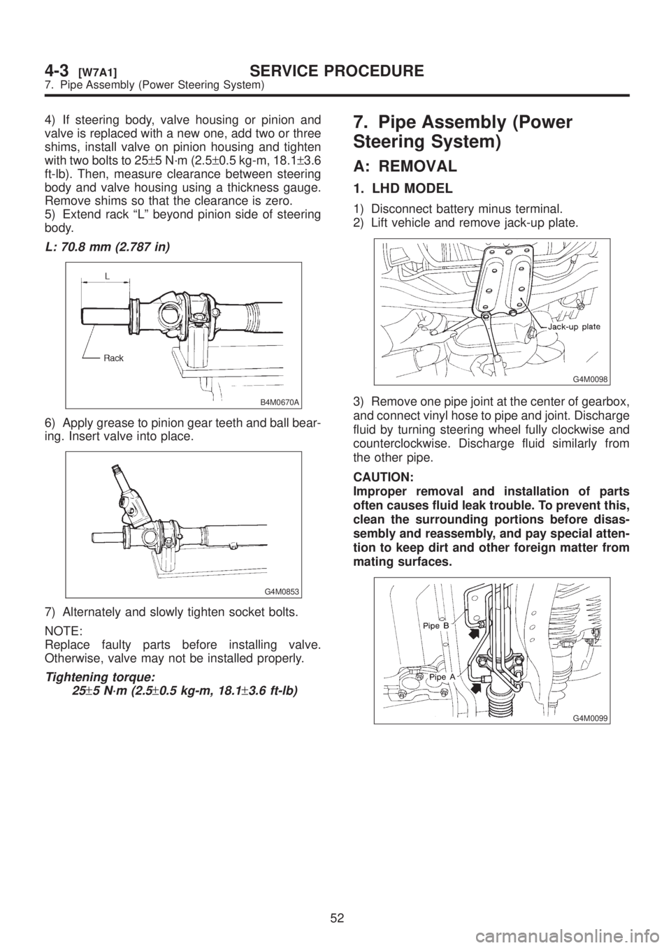
4) If steering body, valve housing or pinion and
valve is replaced with a new one, add two or three
shims, install valve on pinion housing and tighten
with two bolts to 25±5 N´m (2.5±0.5 kg-m, 18.1±3.6
ft-lb). Then, measure clearance between steering
body and valve housing using a thickness gauge.
Remove shims so that the clearance is zero.
5) Extend rack ªLº beyond pinion side of steering
body.
L: 70.8 mm (2.787 in)
B4M0670A
6) Apply grease to pinion gear teeth and ball bear-
ing. Insert valve into place.
G4M0853
7) Alternately and slowly tighten socket bolts.
NOTE:
Replace faulty parts before installing valve.
Otherwise, valve may not be installed properly.
Tightening torque:
25
±5 N´m (2.5±0.5 kg-m, 18.1±3.6 ft-lb)
7. Pipe Assembly (Power
Steering System)
A: REMOVAL
1. LHD MODEL
1) Disconnect battery minus terminal.
2) Lift vehicle and remove jack-up plate.
G4M0098
3) Remove one pipe joint at the center of gearbox,
and connect vinyl hose to pipe and joint. Discharge
fluid by turning steering wheel fully clockwise and
counterclockwise. Discharge fluid similarly from
the other pipe.
CAUTION:
Improper removal and installation of parts
often causes fluid leak trouble. To prevent this,
clean the surrounding portions before disas-
sembly and reassembly, and pay special atten-
tion to keep dirt and other foreign matter from
mating surfaces.
G4M0099
52
4-3[W7A1]SERVICE PROCEDURE
7. Pipe Assembly (Power Steering System)
Page 845 of 1456
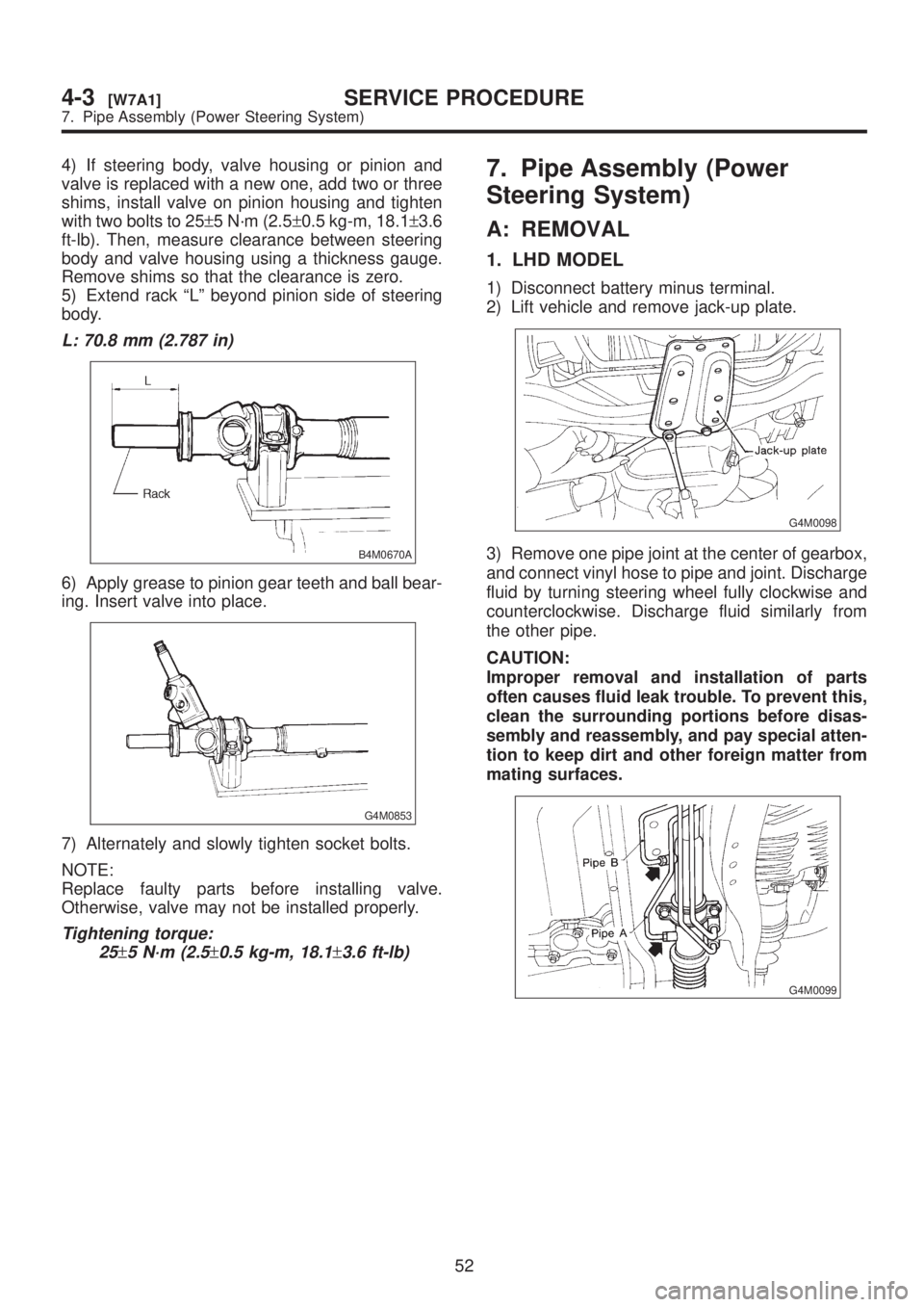
4) If steering body, valve housing or pinion and
valve is replaced with a new one, add two or three
shims, install valve on pinion housing and tighten
with two bolts to 25±5 N´m (2.5±0.5 kg-m, 18.1±3.6
ft-lb). Then, measure clearance between steering
body and valve housing using a thickness gauge.
Remove shims so that the clearance is zero.
5) Extend rack ªLº beyond pinion side of steering
body.
L: 70.8 mm (2.787 in)
B4M0670A
6) Apply grease to pinion gear teeth and ball bear-
ing. Insert valve into place.
G4M0853
7) Alternately and slowly tighten socket bolts.
NOTE:
Replace faulty parts before installing valve.
Otherwise, valve may not be installed properly.
Tightening torque:
25
±5 N´m (2.5±0.5 kg-m, 18.1±3.6 ft-lb)
7. Pipe Assembly (Power
Steering System)
A: REMOVAL
1. LHD MODEL
1) Disconnect battery minus terminal.
2) Lift vehicle and remove jack-up plate.
G4M0098
3) Remove one pipe joint at the center of gearbox,
and connect vinyl hose to pipe and joint. Discharge
fluid by turning steering wheel fully clockwise and
counterclockwise. Discharge fluid similarly from
the other pipe.
CAUTION:
Improper removal and installation of parts
often causes fluid leak trouble. To prevent this,
clean the surrounding portions before disas-
sembly and reassembly, and pay special atten-
tion to keep dirt and other foreign matter from
mating surfaces.
G4M0099
52
4-3[W7A1]SERVICE PROCEDURE
7. Pipe Assembly (Power Steering System)
Page 846 of 1456

4) Remove clamp E from pipes C and D.
G4M0162
5) Disconnect pipe C´D from pipe (on the gearbox
side).
CAUTION:
IWhen disconnecting pipe C´D, use two
wrenches to prevent deformities.
IBe careful to keep pipe connections free
from foreign matter.
G4M0101
6) Remove bolt A.
Disconnect pipe C from oil pump. Disconnect pipe
D from oil tank.
CAUTION:
IDo not allow fluid from the hose end to come
into contact with pulley belt.
ITo prevent foreign matter from entering the
hose and pipe, cover the open ends of them
with a clean cloth.
B4M1159A
2. RHD MODEL
1) Disconnect battery negative terminal.
2) Lift vehicle and remove jack-up plate.
G4M0098
53
[W7A2]4-3SERVICE PROCEDURE
7. Pipe Assembly (Power Steering System)
Page 847 of 1456
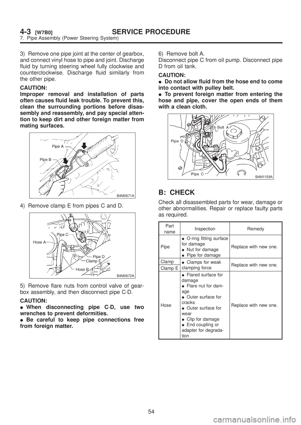
3) Remove one pipe joint at the center of gearbox,
and connect vinyl hose to pipe and joint. Discharge
fluid by turning steering wheel fully clockwise and
counterclockwise. Discharge fluid similarly from
the other pipe.
CAUTION:
Improper removal and installation of parts
often causes fluid leak trouble. To prevent this,
clean the surrounding portions before disas-
sembly and reassembly, and pay special atten-
tion to keep dirt and other foreign matter from
mating surfaces.
B4M0671A
4) Remove clamp E from pipes C and D.
B4M0672A
5) Remove flare nuts from control valve of gear-
box assembly, and then disconnect pipe C´D.
CAUTION:
IWhen disconnecting pipe C´D, use two
wrenches to prevent deformities.
IBe careful to keep pipe connections free
from foreign matter.6) Remove bolt A.
Disconnect pipe C from oil pump. Disconnect pipe
D from oil tank.
CAUTION:
IDo not allow fluid from the hose end to come
into contact with pulley belt.
ITo prevent foreign matter from entering the
hose and pipe, cover the open ends of them
with a clean cloth.
B4M1159A
B: CHECK
Check all disassembled parts for wear, damage or
other abnormalities. Repair or replace faulty parts
as required.
Part
nameInspection Remedy
PipeIO-ring fitting surface
for damage
INut for damage
IPipe for damageReplace with new one.
Clamp
IClamps for weak
clamping forceReplace with new one.
Clamp E
HoseIFlared surface for
damage
IFlare nut for dam-
age
IOuter surface for
cracks
IOuter surface for
wear
IClip for damage
IEnd coupling or
adapter for degrada-
tionReplace with new one.
54
4-3[W7B0]SERVICE PROCEDURE
7. Pipe Assembly (Power Steering System)