Page 151 of 1456

(1) Slowly press the adjuster rod down to the
end surface of the cylinder. Repeat this motion
2 or 3 times.
(2) With the adjuster rod moved all the way up,
apply a pressure of 294 N (30 kg, 66 lb) to it.
Check adjuster rod stiffness.
(3) If the adjuster rod is not stiff and moves
down, replace the automatic belt tension
adjuster assembly with a new one.
CAUTION:
IAlways use a vertical type pressing tool to
move the adjuster rod down.
IDo not use a lateral type vise.
IPush adjuster rod vertically.
IPress-in the push adjuster rod gradually tak-
ing more than three minutes.
IDo not allow press pressure to exceed 9,807
N (1,000 kg, 2,205 lb).
IPress the adjuster rod as far as the end sur-
face of the cylinder. Do not press the adjuster
rod into the cylinder. Doing so may damage the
cylinder.
4) Measure the extension of rod beyond the body.
If it is not within specifications, replace with a new
one.
Rod extension: H
5.7
±0.5 mm (0.224±0.020 in)
H2M2381A
3. BELT TENSION PULLEY
1) Check mating surfaces of timing belt and con-
tact point of adjuster rod for abnormal wear or
scratches. Replace belt tension pulley if faulty.
2) Check belt tension pulley for smooth rotation.
Replace if noise or excessive play is noted.
3) Check belt tension pulley for grease leakage.
4. BELT IDLER
1) Check idler for smooth rotation. Replace if
noise or excessive play is noted.
2) Check outer contacting surfaces of idler pulley
for abnormal wear and scratches.
3) Check idler for grease leakage.
5. SPROCKET
1) Check sprocket teeth for abnormal wear and
scratches.
2) Make sure there is no free play between
sprocket and key.
3) Check crankshaft sprocket notch for sensor for
damage and contamination of foreign matter.
20
2-3b[W2B3]SERVICE PROCEDURE
2. Timing Belt
Page 168 of 1456
2) Remove cylinder head bolts in alphabetical
sequence shown in figure.
CAUTION:
Leave bolts (A) and (D) engaged by three or
four threads to prevent cylinder head from fall-
ing.
B2M1397C
3) While tapping cylinder head with a plastic
hammer, separate it from cylinder block.
Remove bolts (A) and (D) to remove cylinder head.
B2M1397C
4) Remove cylinder head gasket.
5) Similarly, remove right-hand cylinder head.
B: DISASSEMBLY
S2M0420A
(1) Valve shim
(2) Valve lifter
(3) Valve retainer key(4) Valve retainer
(5) Valve spring
(6) Valve oil seal(7) Valve spring seat
(8) Intake valve
(9) Exhaust valve
1) Remove valve shims and valve lifters.
37
[W4B0]2-3bSERVICE PROCEDURE
4. Cylinder Head
Page 169 of 1456

2) Compress the valve spring and remove the
valve spring retainer key. Remove each valve and
valve spring.
ST1 498267600 CYLINDER HEAD TABLE
ST2 499718000 VALVE SPRING REMOVER
CAUTION:
IKeep removed parts in order for re-installing
in their original positions.
IMark each valve to prevent confusion.
IUse extreme care not to damage the lips of
the intake valve oil seals and exhaust valve oil
seals.
B2M1221A
C: INSPECTION
1. CYLINDER HEAD
1) Make sure that no crack or other damage
exists. In addition to visual inspection, inspect
important areas by means of red check.2) Measure the warping of the cylinder head sur-
face that mates with crankcase by using a straight
edge and thickness gauge.
If the warping exceeds 0.05 mm (0.0020 in),
regrind the surface with a surface grinder.
Warping limit:
0.05 mm (0.0020 in)
Grinding limit:
0.3 mm (0.012 in)
Standard height of cylinder head:
127.5 mm (5.02 in)
CAUTION:
Uneven torque for the cylinder head nuts can
cause warping. When reassembling, pay spe-
cial attention to the torque so as to tighten
evenly.
G2M0760
38
2-3b[W4C1]SERVICE PROCEDURE
4. Cylinder Head
Page 173 of 1456
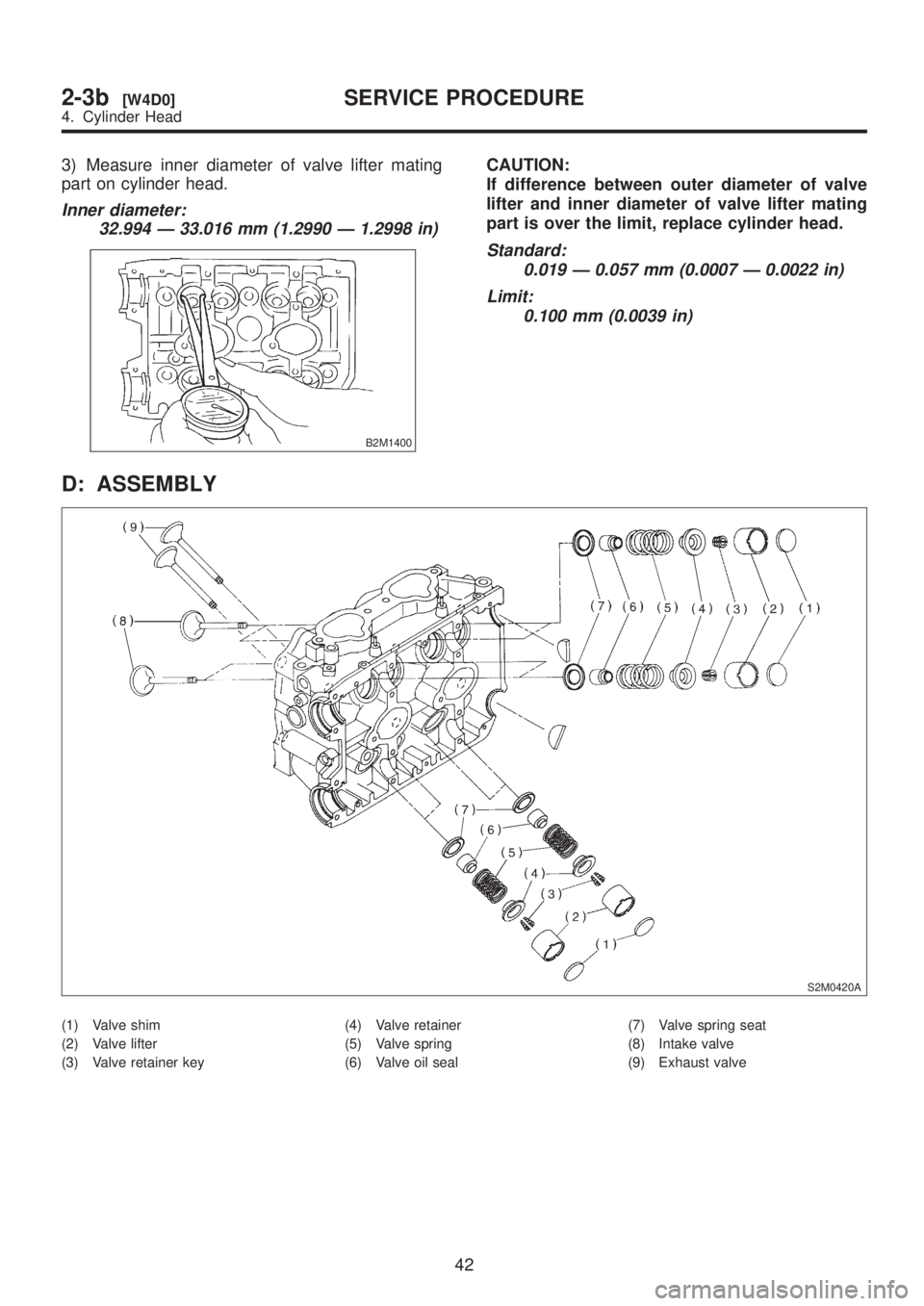
3) Measure inner diameter of valve lifter mating
part on cylinder head.
Inner diameter:
32.994 Ð 33.016 mm (1.2990 Ð 1.2998 in)
B2M1400
CAUTION:
If difference between outer diameter of valve
lifter and inner diameter of valve lifter mating
part is over the limit, replace cylinder head.
Standard:
0.019 Ð 0.057 mm (0.0007 Ð 0.0022 in)
Limit:
0.100 mm (0.0039 in)
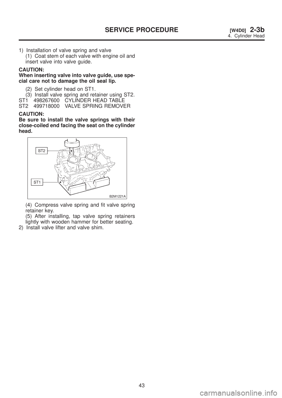
D: ASSEMBLY
S2M0420A
(1) Valve shim
(2) Valve lifter
(3) Valve retainer key(4) Valve retainer
(5) Valve spring
(6) Valve oil seal(7) Valve spring seat
(8) Intake valve
(9) Exhaust valve
42
2-3b[W4D0]SERVICE PROCEDURE
4. Cylinder Head
Page 174 of 1456
1) Installation of valve spring and valve
(1) Coat stem of each valve with engine oil and
insert valve into valve guide.
CAUTION:
When inserting valve into valve guide, use spe-
cial care not to damage the oil seal lip.
(2) Set cylinder head on ST1.
(3) Install valve spring and retainer using ST2.
ST1 498267600 CYLINDER HEAD TABLE
ST2 499718000 VALVE SPRING REMOVER
CAUTION:
Be sure to install the valve springs with their
close-coiled end facing the seat on the cylinder
head.
B2M1221A
(4) Compress valve spring and fit valve spring
retainer key.
(5) After installing, tap valve spring retainers
lightly with wooden hammer for better seating.
2) Install valve lifter and valve shim.
43
[W4D0]2-3bSERVICE PROCEDURE
4. Cylinder Head
Page 475 of 1456
2. Drive Pinion Assembly
B3M0613C
(1) Drive pinion shaft
(2) Roller bearing
(3) Washer
(4) Driven shaft
(5) Key
(6) Woodruff key
(7) Drive pinion collar
(8) Needle bearing
(9) Snap ring (Outer)
(10) Washer
(11) Sub gear
(12) 1st driven gear
(13) Baulk ring(14) 1st-2nd synchronizer hub
(15) Insert key
(16) Reverse driven gear
(17) Outer baulk ring
(18) Synchro cone
(19) Inner baulk ring
(20) 2nd driven gear
(21) 2nd driven gear bush
(22) 3rd-4th driven gear
(23) Driven pinion shim
(24) Roller bearing
(25) 5th driven gear
(26) Lock washer(27) Lock nut
(28) Washer
(29) Thrust bearing
(30) Differential bevel gear sleeve
(31) Washer
(32) Lock washer
(33) Lock nut
Tightening torque: N´m (kg-m, ft-lb)
T1:
29±3 (3.0±0.3, 21.7±2.2)
T2:11 8±8 (12.0±0.8, 86.8±5.8)
T3:265±10 (27±1, 195±7)
7
[C200]3-1COMPONENT PARTS
2. Drive Pinion Assembly
Page 476 of 1456
3. Main Shaft Assembly
A: 2200 cc MODEL
B3M1404A
(1) Oil seal
(2) Needle bearing
(3) Transmission main shaft
(4) Needle bearing
(5) 3rd drive gear
(6) Inner baulk ring
(7) Synchro cone
(8) Outer baulk ring
(9) Coupling sleeve (3rd-4th)
(10) Synchronizer hub (3rd-4th)
(11) Shifting insert key (3rd-4th)
(12) Baulk ring (4th)(13) 4th drive gear
(14) 4th needle bearing race
(15) Needle bearing
(16) 4th gear thrust washer
(17) Ball bearing
(18) 5th gear thrust washer
(19) 5th needle bearing race
(20) Needle bearing
(21) Main shaft rear plate
(22) 5th drive gear
(23) Baulk ring (5th)
(24) Shifting insert key (5th-Rev)(25) Synchronizer hub (5th-Rev)
(26) Coupling sleeve (5th-Rev)
(27) Insert stopper plate
(28) Lock washer
(29) Lock nut
(30) Straight pin
(31) Reverse idler gear shaft
(32) Reverse idler gear
(33) Washer
Tightening torque: N´m (kg-m, ft-lb)
T:
11 8±6 (12.0±0.6, 86.8±4.3)
8
3-1[C3A0]COMPONENT PARTS
3. Main Shaft Assembly
Page 477 of 1456
B: 2500 cc MODEL
B3M1357A
(1) Oil seal
(2) Needle bearing
(3) Transmission main shaft
(4) Needle bearing
(5) 3rd drive gear
(6) Inner baulk ring
(7) Synchro cone (3rd)
(8) Outer baulk ring
(9) Coupling sleeve (3rd-4th)
(10) Synchronizer hub (3rd-4th)
(11) Shift insert key (3rd-4th)
(12) 4th baulk ring
(13) 4th drive gear
(14) 4th needle bearing race(15) Needle bearing
(16) 4th gear thrust washer
(17) Ball bearing
(18) 5th gear thrust washer
(19) 5th needle bearing race
(20) Needle bearing
(21) Main shaft rear plate
(22) 5th drive gear
(23) 5th baulk ring
(24) Shift insert key (5th-Rev)
(25) Synchronizer hub (5th-Rev)
(26) Coupling sleeve
(27) Rev baulk ring
(28) Synchro cone (Rev)(29) Ball bearing
(30) Synchro cone stopper
(31) Snap ring
(32) Lock washer
(33) Lock nut
(34) Straight pin
(35) Reverse idler gear shaft
(36) Reverse idler gear
(37) Washer
Tightening torque: N´m (kg-m, ft-lb)
T:
11 8±6 (12.0±0.6, 86.8±4.3)
9
[C3B0]3-1COMPONENT PARTS
3. Main Shaft Assembly