Page 739 of 1456
CAUTION:
ICheck that hose clip is positioned properly.
ICheck brake hose for twisting, or excessive
tension.
IModels equipped with ABS:
Do not subject ABS sensor harness to exces-
sive tension.
6) Be sure to bleed air from brake system.
7) Lower vehicle and tighten wheel nut.
Tightening torque:
88
±10 N´m (9±1 kg-m, 65±7 ft-lb)
8) Sedan:
Install rear seat backrest and rear seat cushion.
Wagon:
Install strut cap of rear quarter trim.
NOTE:
Check wheel alignment and adjust if necessary.
35
[W9E0]4-1SERVICE PROCEDURE
9. Rear Strut
Page 740 of 1456
10. Rear Crossmember
A: REMOVAL
B4M0572B
(1) Crossmember
(2) Floating bushing
(3) Adjusting bolt
(4) Stopper
(5) Stabilizer link
(6) Rear lateral link
(7) Front lateral link
(8) Washer(9) Cap (Protection)
(10) Trailing link
(11) Self-locking nut
(12) Crossmember reinforcement
lower (Sedan model only)Tightening torque: N´m (kg-m, ft-lb)
T1:
25±7 (2.5±0.7, 18.1±5.1)
T2:44±6 (4.5±0.6, 32.5±4.3)
T3:98±15 (10.0±1.5, 72±11 )
T4:11 3±15 (11.5±1.5, 83±11 )
T5:127±20 (13.0±2.0, 94±14)
T6:137±20 (14.0±2.0, 101±14)
CAUTION:
Do not subject ABS sensor harness to exces-
sive tension. (ABS equipped models.)
1) Separate front exhaust pipe and rear exhaust
pipe.
2) Remove rear exhaust pipe and muffler.
3) Remove crossmember reinforcement lower.
(Sedan model only)
4) Remove rear differential. 5) Place transmission jack under rear crossmem-
ber.
G4M0544
36
4-1[W10A0]SERVICE PROCEDURE
10. Rear Crossmember
Page 755 of 1456
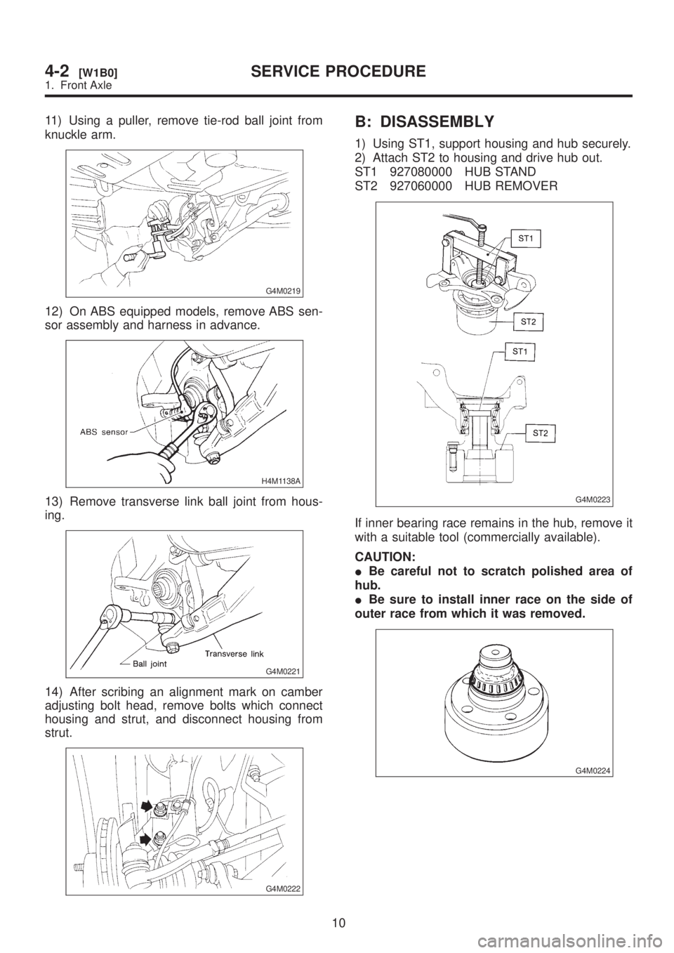
11) Using a puller, remove tie-rod ball joint from
knuckle arm.
G4M0219
12) On ABS equipped models, remove ABS sen-
sor assembly and harness in advance.
H4M1138A
13) Remove transverse link ball joint from hous-
ing.
G4M0221
14) After scribing an alignment mark on camber
adjusting bolt head, remove bolts which connect
housing and strut, and disconnect housing from
strut.
G4M0222
B: DISASSEMBLY
1) Using ST1, support housing and hub securely.
2) Attach ST2 to housing and drive hub out.
ST1 927080000 HUB STAND
ST2 927060000 HUB REMOVER
G4M0223
If inner bearing race remains in the hub, remove it
with a suitable tool (commercially available).
CAUTION:
IBe careful not to scratch polished area of
hub.
IBe sure to install inner race on the side of
outer race from which it was removed.
G4M0224
10
4-2[W1B0]SERVICE PROCEDURE
1. Front Axle
Page 756 of 1456

3) Remove disc cover from housing.
G4M0225
4) Using a standard screwdriver, remove outer
and inner oil seals.
CAUTION:
Do not use old oil seals.
5) Using flat bladed screwdriver, remove snap
ring.
H4M1001
6) Using ST1, support housing securely.
7) Using ST2, press inner race to drive out outer
bearing.
ST1 927400000 HOUSING STAND
ST2 927100000 BEARING REMOVER
CAUTION:
IDo not remove outer race unless it is faulty.
IDiscard outer race after removal.
IDo not replace inner or outer race sepa-
rately; always replace as a unit.
G4M0227
8) Loosen bolts which secure tone wheel to hub.
Remove tone wheel (only vehicle equipped with
ABS).9) Using ST and a hydraulic press, drive hub bolts
out.
ST 927080000 HUB STAND
CAUTION:
Be careful not to hammer hub bolts. This may
deform hub.
G4M0228
C: INSPECTION
Check the removed parts for wear and damage. If
defective, replace with new ones.
CAUTION:
IIf bearing is faulty, replace it as a bearing set.
IBe sure to replace oil seal at every overhaul.
H4M1002A
D: ASSEMBLY
1) Attach hub to ST securely.
ST 927080000 HUB STAND
G4M0230
2) Using a hydraulic press, press new hub bolts
into place.
11
[W1D0]4-2SERVICE PROCEDURE
1. Front Axle
Page 757 of 1456

CAUTION:
Be sure to press hub bolts until their seating
surfaces contact the hub.
NOTE:
Use 12 mm (0.47 in) dia. holes in HUB STAND to
prevent bolts from tilting.
3) Remove foreign particles (dust, rust, etc.) from
mating surfaces of hub and tone wheel, and install
tone wheel to hub (only vehicle equipped with
ABS).
CAUTION:
IBe careful not to damage tone wheel teeth.
IEnsure tone wheel closely contacts hub.
G4M0231
4) Clean dust or foreign particles from inside the
housing.
5) Using ST1 and ST2, press a new bearing into
place.
ST1 927400000 HOUSING STAND
ST2 927100000 BEARING REMOVER
CAUTION:
IAlways press outer race when installing
bearing.
IBe careful not to remove plastic lock from
inner race when installing bearing.
ICharge bearing with new grease when outer
race is not removed.
G4M0232
6) Install snap ring in its groove.
NOTE:
Make sure to install it firmly to groove.7) Using ST1 and ST2, press outer oil seal until it
contacts the bottom of housing.
ST1 927410000 OIL SEAL INSTALLER
ST2 927400000 HOUSING STAND
G4M0233
8) Using ST1 and ST2, press inner oil seal until it
contacts circlip.
ST1 927410000 OIL SEAL INSTALLER
ST2 927400000 HOUSING STAND
G4M0234
9) Invert ST and housing.
ST 927400000 HOUSING STAND
10) Apply sufficient grease to oil seal lip.
Specified grease:
SHELL 6459N
CAUTION:
IIf specified grease is not available, remove
bearing grease and apply Auto Rex A instead.
IDo not mix different types of grease.
11) Install disc cover to housing the three bolts.
Tightening torque:
14
±4 N´m (1.4±0.4 kg-m, 10.1±2.9 ft-lb)
12
4-2[W1D0]SERVICE PROCEDURE
1. Front Axle
Page 758 of 1456
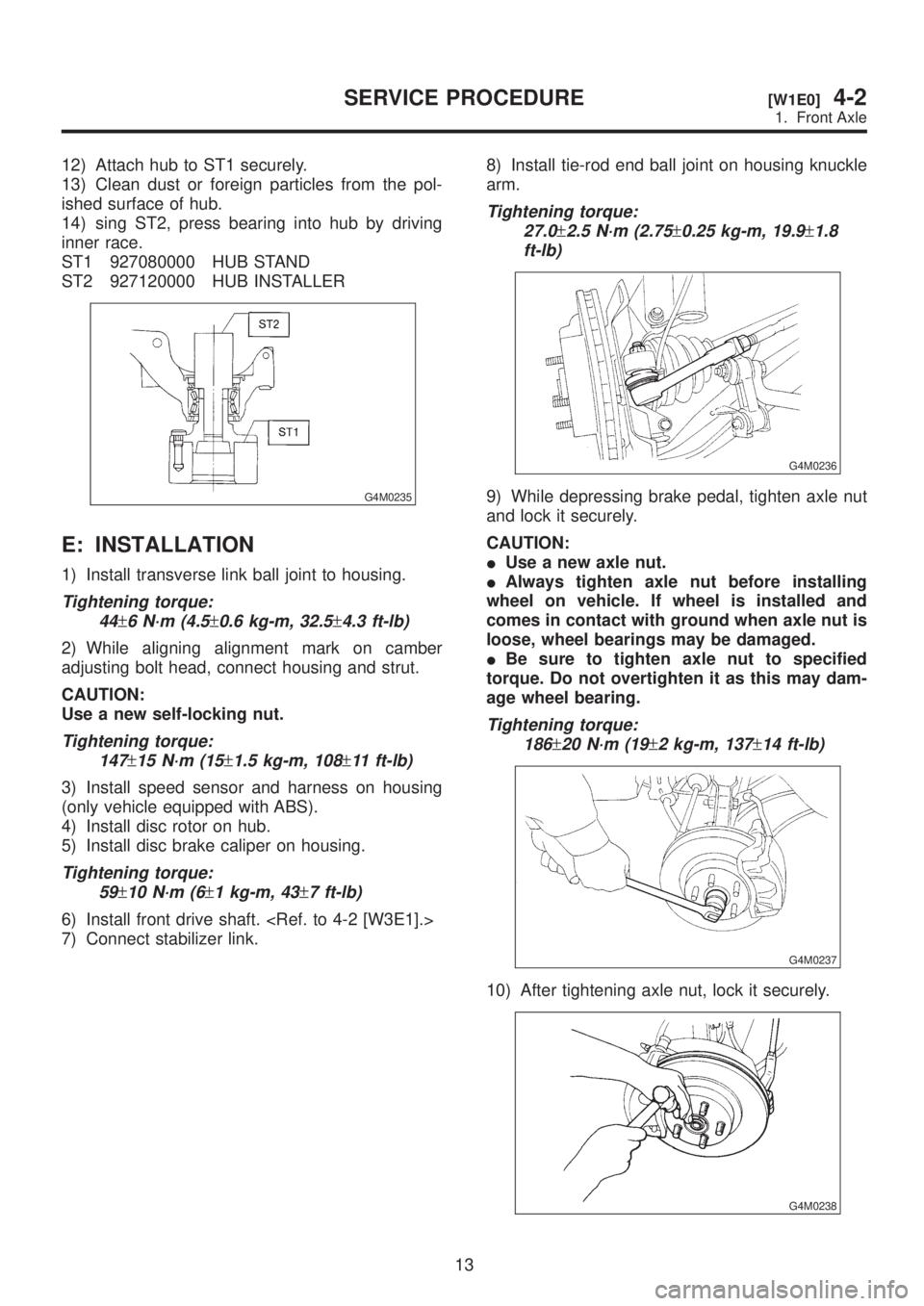
12) Attach hub to ST1 securely.
13) Clean dust or foreign particles from the pol-
ished surface of hub.
14) sing ST2, press bearing into hub by driving
inner race.
ST1 927080000 HUB STAND
ST2 927120000 HUB INSTALLER
G4M0235
E: INSTALLATION
1) Install transverse link ball joint to housing.
Tightening torque:
44
±6 N´m (4.5±0.6 kg-m, 32.5±4.3 ft-lb)
2) While aligning alignment mark on camber
adjusting bolt head, connect housing and strut.
CAUTION:
Use a new self-locking nut.
Tightening torque:
147
±15 N´m (15±1.5 kg-m, 108±11 ft-lb)
3) Install speed sensor and harness on housing
(only vehicle equipped with ABS).
4) Install disc rotor on hub.
5) Install disc brake caliper on housing.
Tightening torque:
59
±10 N´m (6±1 kg-m, 43±7 ft-lb)
6) Install front drive shaft.
7) Connect stabilizer link.8) Install tie-rod end ball joint on housing knuckle
arm.
Tightening torque:
27.0
±2.5 N´m (2.75±0.25 kg-m, 19.9±1.8
ft-lb)
G4M0236
9) While depressing brake pedal, tighten axle nut
and lock it securely.
CAUTION:
IUse a new axle nut.
IAlways tighten axle nut before installing
wheel on vehicle. If wheel is installed and
comes in contact with ground when axle nut is
loose, wheel bearings may be damaged.
IBe sure to tighten axle nut to specified
torque. Do not overtighten it as this may dam-
age wheel bearing.
Tightening torque:
186
±20 N´m (19±2 kg-m, 137±14 ft-lb)
G4M0237
10) After tightening axle nut, lock it securely.
G4M0238
13
[W1E0]4-2SERVICE PROCEDURE
1. Front Axle
Page 761 of 1456

8) Disconnect parking brake cable end.
G4M0241
9) Remove bolts which secure trailing link assem-
bly to rear housing.
CAUTION:
Discard old self-locking nut. Replace with a
new one.
G4M0246
10) Remove bolts which secure lateral link assem-
bly to rear housing.
CAUTION:
Discard old self-locking nut. Replace with a
new one.
G4M0245
11) Disengage BJ from housing splines, and
remove rear drive shaft assembly. If it is hard to
remove, use STs.
ST1 926470000 AXLE SHAFT PULLER
ST2 927140000 PLATE
CAUTION:
IBe careful not to damage oil seal lip when
removing rear drive shaft.
IWhen rear drive shaft is to be replaced, also
replace inner oil seal with a new one.
G4M0247
12) Remove rear ABS sensor from back plate
(only vehicle equipped with ABS).
H4M1139A
13) Remove bolts which secure rear housing to
strut, and separate the two.
G4M0249
2. DRUM BRAKE
1) Disconnect ground cable from battery.
2) Jack-up vehicle, and remove rear wheel cap
and wheels.
15
[W2A2]4-2SERVICE PROCEDURE
2. Rear Axle
Page 764 of 1456
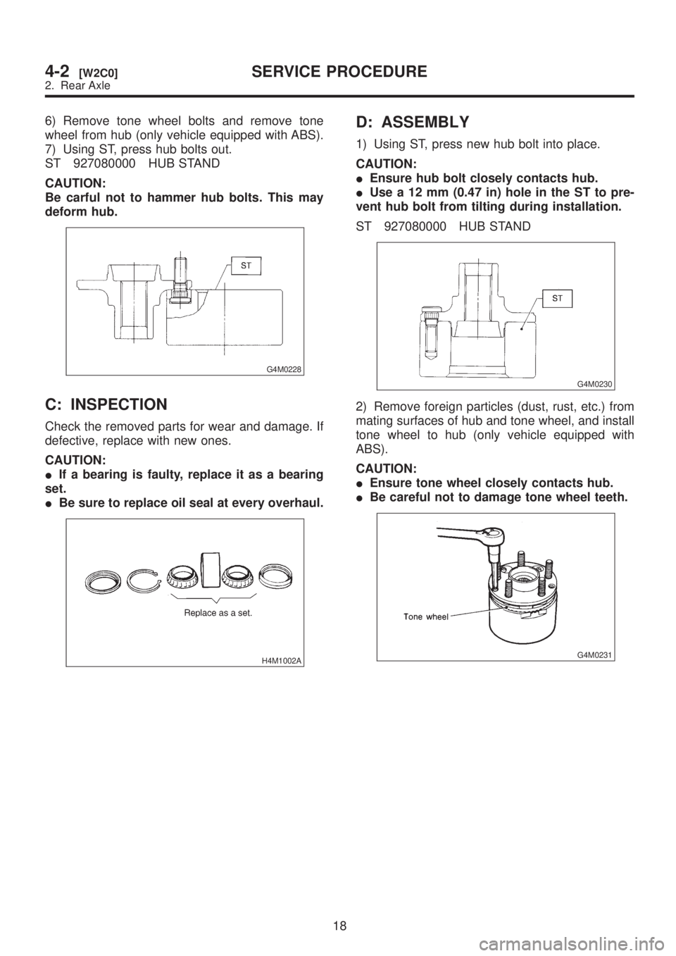
6) Remove tone wheel bolts and remove tone
wheel from hub (only vehicle equipped with ABS).
7) Using ST, press hub bolts out.
ST 927080000 HUB STAND
CAUTION:
Be carful not to hammer hub bolts. This may
deform hub.
G4M0228
C: INSPECTION
Check the removed parts for wear and damage. If
defective, replace with new ones.
CAUTION:
IIf a bearing is faulty, replace it as a bearing
set.
IBe sure to replace oil seal at every overhaul.
H4M1002A
D: ASSEMBLY
1) Using ST, press new hub bolt into place.
CAUTION:
IEnsure hub bolt closely contacts hub.
IUse a 12 mm (0.47 in) hole in the ST to pre-
vent hub bolt from tilting during installation.
ST 927080000 HUB STAND
G4M0230
2) Remove foreign particles (dust, rust, etc.) from
mating surfaces of hub and tone wheel, and install
tone wheel to hub (only vehicle equipped with
ABS).
CAUTION:
IEnsure tone wheel closely contacts hub.
IBe careful not to damage tone wheel teeth.
G4M0231
18
4-2[W2C0]SERVICE PROCEDURE
2. Rear Axle