Page 234 of 345
3. Rear Gate
A: REMOVAL AND INSTALLATION
CAUTION:
IBe careful not to scratch coated surfaces of
vehicle body and window glass during
removal. Place a cloth over the affected area.
IBe careful not to damage trim panels.
IUse an assistant when handling heavy parts.
IBe careful not to damage or lose small parts.
1. REAR GATE ASSEMBLY
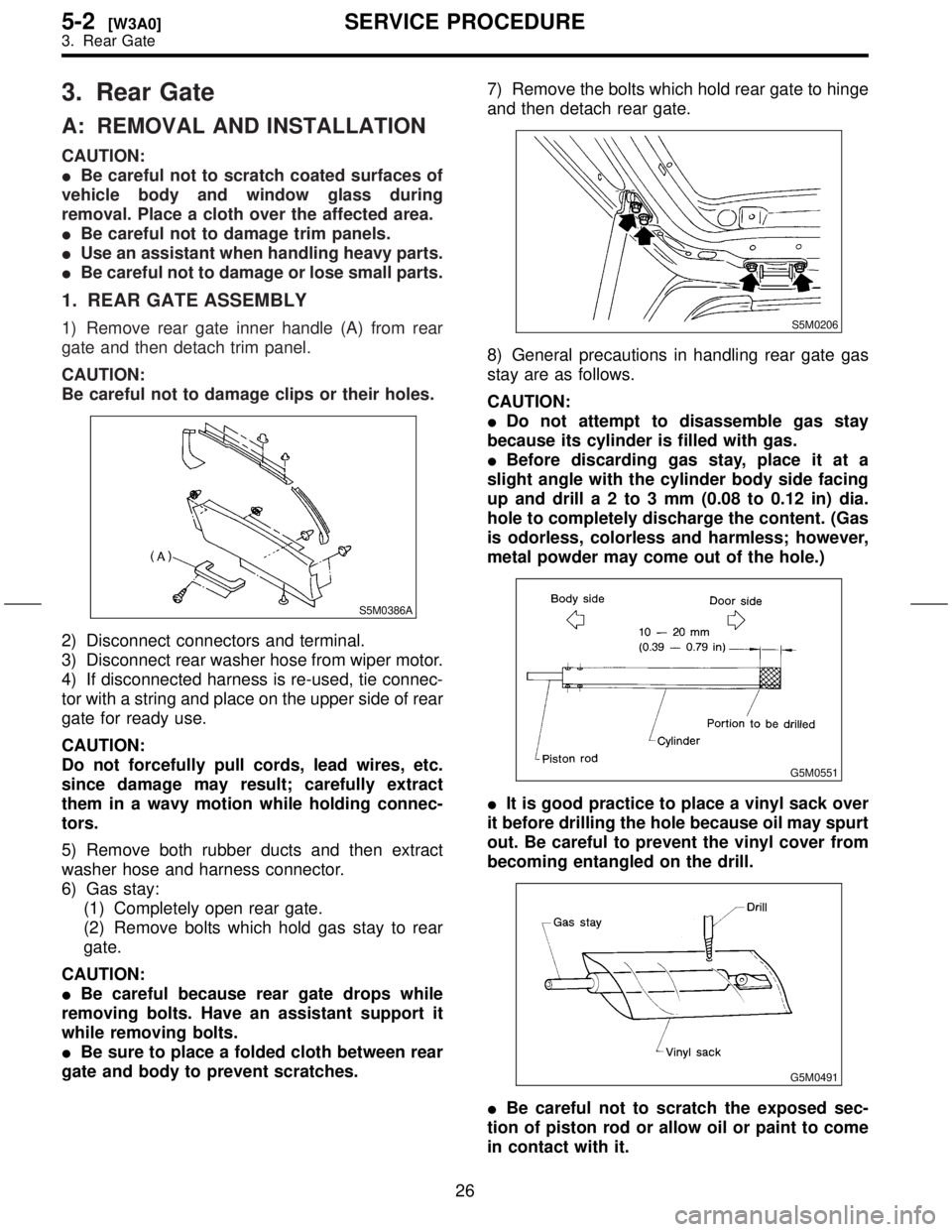
1) Remove rear gate inner handle (A) from rear
gate and then detach trim panel.
CAUTION:
Be careful not to damage clips or their holes.
S5M0386A
2) Disconnect connectors and terminal.
3) Disconnect rear washer hose from wiper motor.
4) If disconnected harness is re-used, tie connec-
tor with a string and place on the upper side of rear
gate for ready use.
CAUTION:
Do not forcefully pull cords, lead wires, etc.
since damage may result; carefully extract
them in a wavy motion while holding connec-
tors.
5) Remove both rubber ducts and then extract
washer hose and harness connector.
6) Gas stay:
(1) Completely open rear gate.
(2) Remove bolts which hold gas stay to rear
gate.
CAUTION:
IBe careful because rear gate drops while
removing bolts. Have an assistant support it
while removing bolts.
IBe sure to place a folded cloth between rear
gate and body to prevent scratches.7) Remove the bolts which hold rear gate to hinge
and then detach rear gate.
S5M0206
8) General precautions in handling rear gate gas
stay are as follows.
CAUTION:
IDo not attempt to disassemble gas stay
because its cylinder is filled with gas.
IBefore discarding gas stay, place it at a
slight angle with the cylinder body side facing
up and drilla2to3mm(0.08 to 0.12 in) dia.
hole to completely discharge the content. (Gas
is odorless, colorless and harmless; however,
metal powder may come out of the hole.)
G5M0551
IIt is good practice to place a vinyl sack over
it before drilling the hole because oil may spurt
out. Be careful to prevent the vinyl cover from
becoming entangled on the drill.
G5M0491
IBe careful not to scratch the exposed sec-
tion of piston rod or allow oil or paint to come
in contact with it.
26
5-2[W3A0]SERVICE PROCEDURE
3. Rear Gate
Page 238 of 345
5. Windshield
A: REMOVAL
1. USING WINDSHIELD KNIFE
The following procedure for the front windshield
can also be applied to other window glass.
1) Remove wiper arm and cowl panel.
2) Remove front side molding and upper front
molding.
3) Remove glass:
(1) Put protective tape on body to prevent dam-
age.
(2) Apply soapy water to the surface of the
adhesive agent so the knife blade slides
smoothly.
(3) Cut off excess adhesive agent.
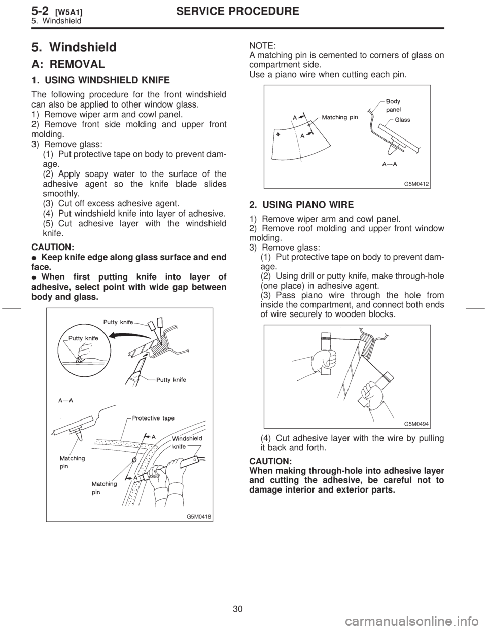
(4) Put windshield knife into layer of adhesive.
(5) Cut adhesive layer with the windshield
knife.
CAUTION:
IKeep knife edge along glass surface and end
face.
IWhen first putting knife into layer of
adhesive, select point with wide gap between
body and glass.
G5M0418
NOTE:
A matching pin is cemented to corners of glass on
compartment side.
Use a piano wire when cutting each pin.
G5M0412
2. USING PIANO WIRE
1) Remove wiper arm and cowl panel.
2) Remove roof molding and upper front window
molding.
3) Remove glass:
(1) Put protective tape on body to prevent dam-
age.
(2) Using drill or putty knife, make through-hole
(one place) in adhesive agent.
(3) Pass piano wire through the hole from
inside the compartment, and connect both ends
of wire securely to wooden blocks.
G5M0494
(4) Cut adhesive layer with the wire by pulling
it back and forth.
CAUTION:
When making through-hole into adhesive layer
and cutting the adhesive, be careful not to
damage interior and exterior parts.
30
5-2[W5A1]SERVICE PROCEDURE
5. Windshield
Page 240 of 345
8) Installation of glass:
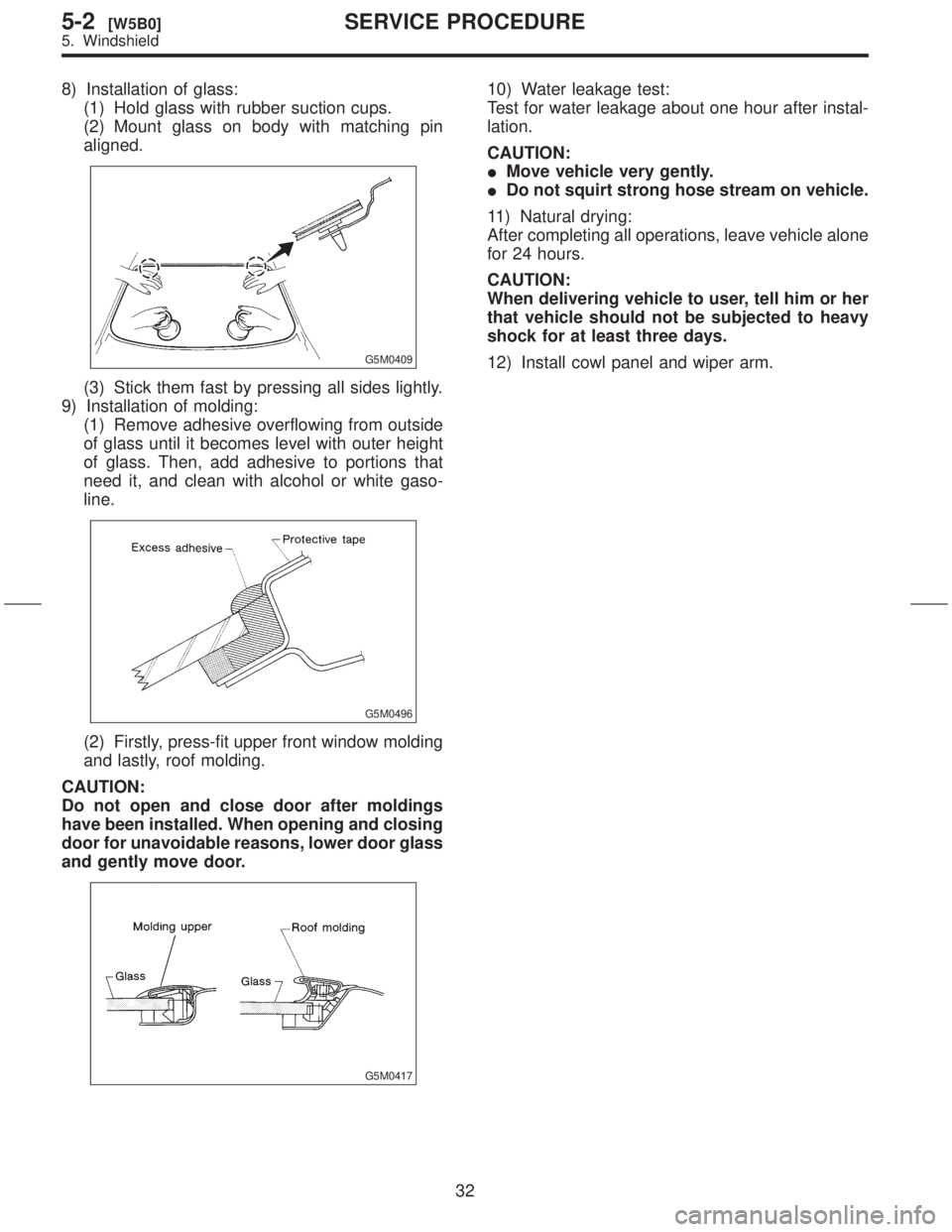
(1) Hold glass with rubber suction cups.
(2) Mount glass on body with matching pin
aligned.
G5M0409
(3) Stick them fast by pressing all sides lightly.
9) Installation of molding:
(1) Remove adhesive overflowing from outside
of glass until it becomes level with outer height
of glass. Then, add adhesive to portions that
need it, and clean with alcohol or white gaso-
line.
G5M0496
(2) Firstly, press-fit upper front window molding
and lastly, roof molding.
CAUTION:
Do not open and close door after moldings
have been installed. When opening and closing
door for unavoidable reasons, lower door glass
and gently move door.
G5M0417
10) Water leakage test:
Test for water leakage about one hour after instal-
lation.
CAUTION:
IMove vehicle very gently.
IDo not squirt strong hose stream on vehicle.
11) Natural drying:
After completing all operations, leave vehicle alone
for 24 hours.
CAUTION:
When delivering vehicle to user, tell him or her
that vehicle should not be subjected to heavy
shock for at least three days.
12) Install cowl panel and wiper arm.
32
5-2[W5B0]SERVICE PROCEDURE
5. Windshield
Page 287 of 345

11) Disconnect connectors and then detach com-
bination switch assembly.
12) Remove lighting switch and wiper switch from
roll connector.
B5M0940
B: ADJUSTMENT
1. CENTERING ROLL CONNECTOR
Before installing steering wheel, make sure to cen-
ter roll connector built into combination switch.
1) Make sure that front wheels are positioned
straight ahead.
2) Install steering gearbox, steering shaft and
combination switch properly. Turn roll connector
pin (A) clockwise until it stops.
3) Then, back off roll connector pin (A) approxi-
mately 2.5 turns until ªGº marks aligned.
H5M0663B
C: INSTALLATION
CAUTION:
Failure to do this might damage roll connector.
1) Install lighting switch and wiper switch to roll
connector.
2) Before installing combination switch, check to
ensure that combination switch is off and front
wheels are set in the straight ahead position.
3) Install combination switch assembly and then
connect connectors.
4) Install column cover and centering roll connec-
tor.
5) Install steering wheel in neutral position. Care-
fully insert roll connector pin (A) into hole on steer-
ing wheel.
NOTE:
If steering wheel angle requires fine adjustment,
adjust tie-rod.
H5M0663B
6) Install airbag module and lower cover in the
reverse order of removal.
15
[W8C0]5-5SERVICE PROCEDURE
8. Roll Connector
Page 325 of 345
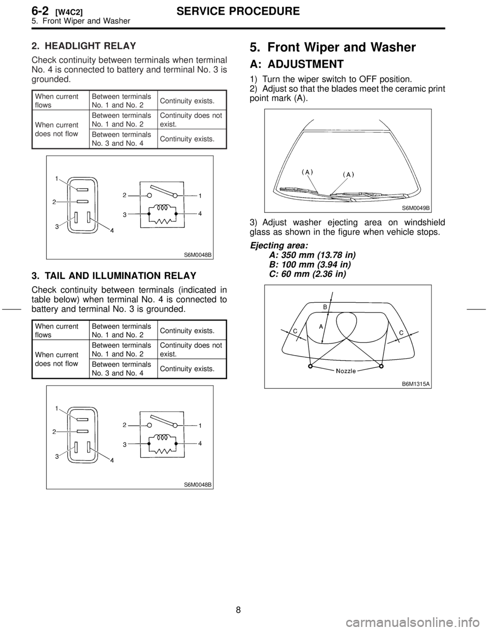
2. HEADLIGHT RELAY
Check continuity between terminals when terminal
No. 4 is connected to battery and terminal No. 3 is
grounded.
When current
flowsBetween terminals
No. 1 and No. 2Continuity exists.
When current
does not flowBetween terminals
No. 1 and No. 2Continuity does not
exist.
Between terminals
No. 3 and No. 4Continuity exists.
S6M0048B
3. TAIL AND ILLUMINATION RELAY
Check continuity between terminals (indicated in
table below) when terminal No. 4 is connected to
battery and terminal No. 3 is grounded.
When current
flowsBetween terminals
No. 1 and No. 2Continuity exists.
When current
does not flowBetween terminals
No. 1 and No. 2Continuity does not
exist.
Between terminals
No. 3 and No. 4Continuity exists.
S6M0048B
5. Front Wiper and Washer
A: ADJUSTMENT
1) Turn the wiper switch to OFF position.
2) Adjust so that the blades meet the ceramic print
point mark (A).
S6M0049B
3) Adjust washer ejecting area on windshield
glass as shown in the figure when vehicle stops.
Ejecting area:
A: 350 mm (13.78 in)
B: 100 mm (3.94 in)
C: 60 mm (2.36 in)
B6M1315A
8
6-2[W4C2]SERVICE PROCEDURE
5. Front Wiper and Washer
Page 326 of 345
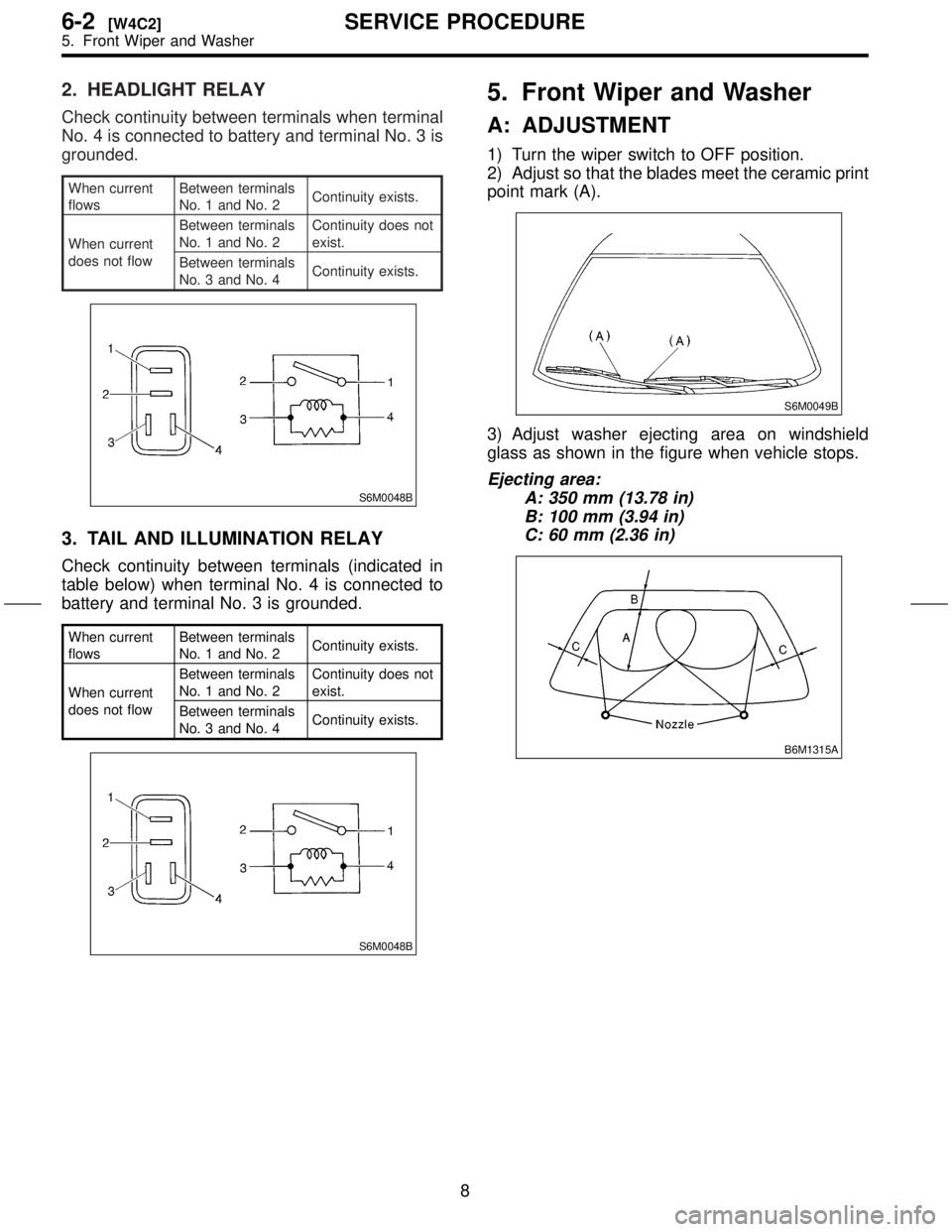
2. HEADLIGHT RELAY
Check continuity between terminals when terminal
No. 4 is connected to battery and terminal No. 3 is
grounded.
When current
flowsBetween terminals
No. 1 and No. 2Continuity exists.
When current
does not flowBetween terminals
No. 1 and No. 2Continuity does not
exist.
Between terminals
No. 3 and No. 4Continuity exists.
S6M0048B
3. TAIL AND ILLUMINATION RELAY
Check continuity between terminals (indicated in
table below) when terminal No. 4 is connected to
battery and terminal No. 3 is grounded.
When current
flowsBetween terminals
No. 1 and No. 2Continuity exists.
When current
does not flowBetween terminals
No. 1 and No. 2Continuity does not
exist.
Between terminals
No. 3 and No. 4Continuity exists.
S6M0048B
5. Front Wiper and Washer
A: ADJUSTMENT
1) Turn the wiper switch to OFF position.
2) Adjust so that the blades meet the ceramic print
point mark (A).
S6M0049B
3) Adjust washer ejecting area on windshield
glass as shown in the figure when vehicle stops.
Ejecting area:
A: 350 mm (13.78 in)
B: 100 mm (3.94 in)
C: 60 mm (2.36 in)
B6M1315A
8
6-2[W4C2]SERVICE PROCEDURE
5. Front Wiper and Washer
Page 327 of 345

B: REMOVAL AND INSTALLATION
1. BLADE
1) Pull out blade following the arrow direction,
from arm while pushing up locking clip (A).
B6M0107B
2) Install in the reverse order of removal.
2. WIPER ARM
1) Open front hood.
2) Remove cap. Remove the nut which secure
wiper arm, and remove wiper arm.
S6M0050
3) Install in the reverse order of removal.
NOTE:
Remove metal sludge from the wiper arm fixture
before installing it.
Tightening torque:
20
±3 N´m (2.0±0.3 kg-m, 14.5±2.2 ft-lb)
3. WIPER MOTOR AND LINK
1) Disconnect ground cable from battery.
2) Detach cowl panel.
NOTE:
Apply silicone oil or soap water to both sides of
cowl net to facilitate removal.3) Disconnect electric connector, and remove
motor attaching bolts.
Tightening torque:
5.9
±1.5 N´m (0.6±0.15 kg-m, 4.3±1.1 ft-lb)
S6M0051
4) Remove cowl cover.
5) Remove nut securing motor link on the back
side of motor.
Tightening torque:
15
±3 N´m (1.5±0.3 kg-m, 11±2.2 ft-lb)
S6M0052
6) Remove bolts which secure sleeve unit.
Tightening torque:
5.9
±1.5 N´m (0.6±0.15 kg-m, 4.3±1.1 ft-lb)
S6M0053
9
[W5B3]6-2SERVICE PROCEDURE
5. Front Wiper and Washer
Page 328 of 345
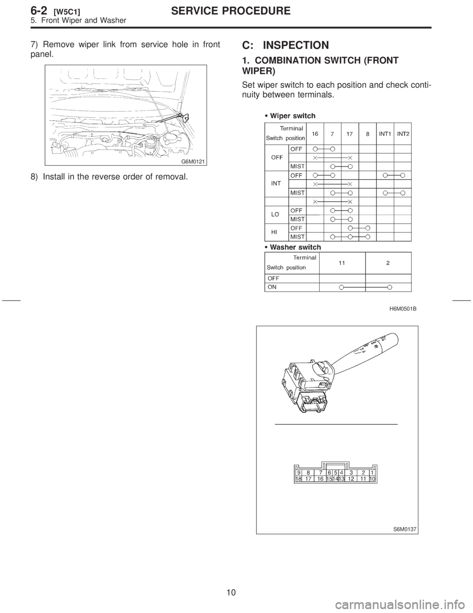
7) Remove wiper link from service hole in front
panel.
G6M0121
8) Install in the reverse order of removal.
C: INSPECTION
1. COMBINATION SWITCH (FRONT
WIPER)
Set wiper switch to each position and check conti-
nuity between terminals.
H6M0501B
S6M0137
10
6-2[W5C1]SERVICE PROCEDURE
5. Front Wiper and Washer