Page 64 of 345

1. Combination Meter
A: DIAGNOSTICS PROCEDURE
If speedometer does not operate, or operates
abnormally, check combination meter circuit.
CAUTION:
Make sure that trouble code of vehicle speed
sensor system appears in electrical system on-
board diagnosis.
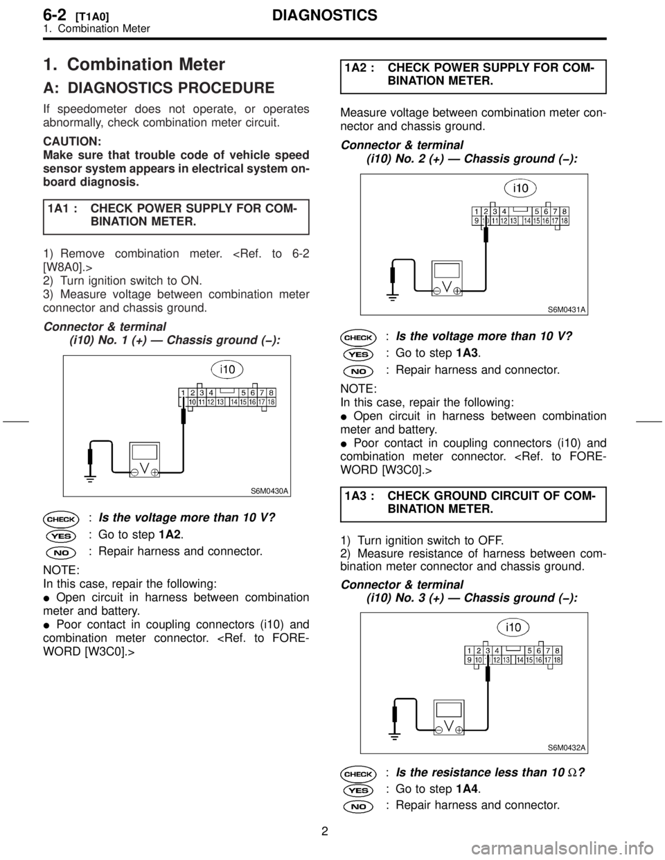
1A1 : CHECK POWER SUPPLY FOR COM-
BINATION METER.
1) Remove combination meter.
[W8A0].>
2) Turn ignition switch to ON.
3) Measure voltage between combination meter
connector and chassis ground.
Connector & terminal
(i10) No. 1 (+) Ð Chassis ground (þ):
S6M0430A
:Is the voltage more than 10 V?
: Go to step1A2.
: Repair harness and connector.
NOTE:
In this case, repair the following:
IOpen circuit in harness between combination
meter and battery.
IPoor contact in coupling connectors (i10) and
combination meter connector.
WORD [W3C0].>1A2 : CHECK POWER SUPPLY FOR COM-
BINATION METER.
Measure voltage between combination meter con-
nector and chassis ground.
Connector & terminal
(i10) No. 2 (+) Ð Chassis ground (þ):
S6M0431A
:Is the voltage more than 10 V?
: Go to step1A3.
: Repair harness and connector.
NOTE:
In this case, repair the following:
IOpen circuit in harness between combination
meter and battery.
IPoor contact in coupling connectors (i10) and
combination meter connector.
WORD [W3C0].>
1A3 : CHECK GROUND CIRCUIT OF COM-
BINATION METER.
1) Turn ignition switch to OFF.
2) Measure resistance of harness between com-
bination meter connector and chassis ground.
Connector & terminal
(i10) No. 3 (+) Ð Chassis ground (þ):
S6M0432A
:Is the resistance less than 10W?
: Go to step1A4.
: Repair harness and connector.
2
6-2[T1A0]DIAGNOSTICS
1. Combination Meter
Page 66 of 345

1A8 : CHECK VEHICLE SPEED SENSOR.
1) Connect connector to vehicle speed sensor.
2) Set the vehicle on a free roller, or lift-up the
vehicle and support with safety stands.
WARNING:
Be careful not to get caught in the rotating
wheels.
3) Set oscilloscope to vehicle speed sensor con-
nector terminals.
Positive probe; (B17) No. 1
Earth lead; (B17) No. 2
H6M0789A
4) Drive the vehicle at speed greater than 20 km/h
(12 MPH).
5) Measure signal voltage indicated on oscillo-
scope.
H6M0790A
:Is the voltage more than 5 V?
: Repair or replace speedometer.
: Replace vehicle speed sensor.
6-2 [W1100].>1A9 : CHECK HARNESS CONNECTOR
BETWEEN COMBINATION METER
AND AUTOMATIC TRANSMISSION
CONTROL MODULE.
1) Disconnect connector from automatic transmis-
sion control module.
2) Measure resistance between combination
meter connector (i10) and automatic transmission
control module connector (B56).
CAUTION:
To measure the voltage and/or resistance, use
a tapered pin with a diameter of less than 0.64
mm (0.025 in). Do not insert the pin more than
5 mm (0.20 in).
Connector & terminal
(i10) No. 7 Ð (B56) No. 17:
S6M0434A
:Is the resistance less than 10W?
: Go to step1A10.
: Repair harness connector between
combination meter and automatic trans-
mission control module.
4
6-2[T1A8]DIAGNOSTICS
1. Combination Meter
Page 67 of 345

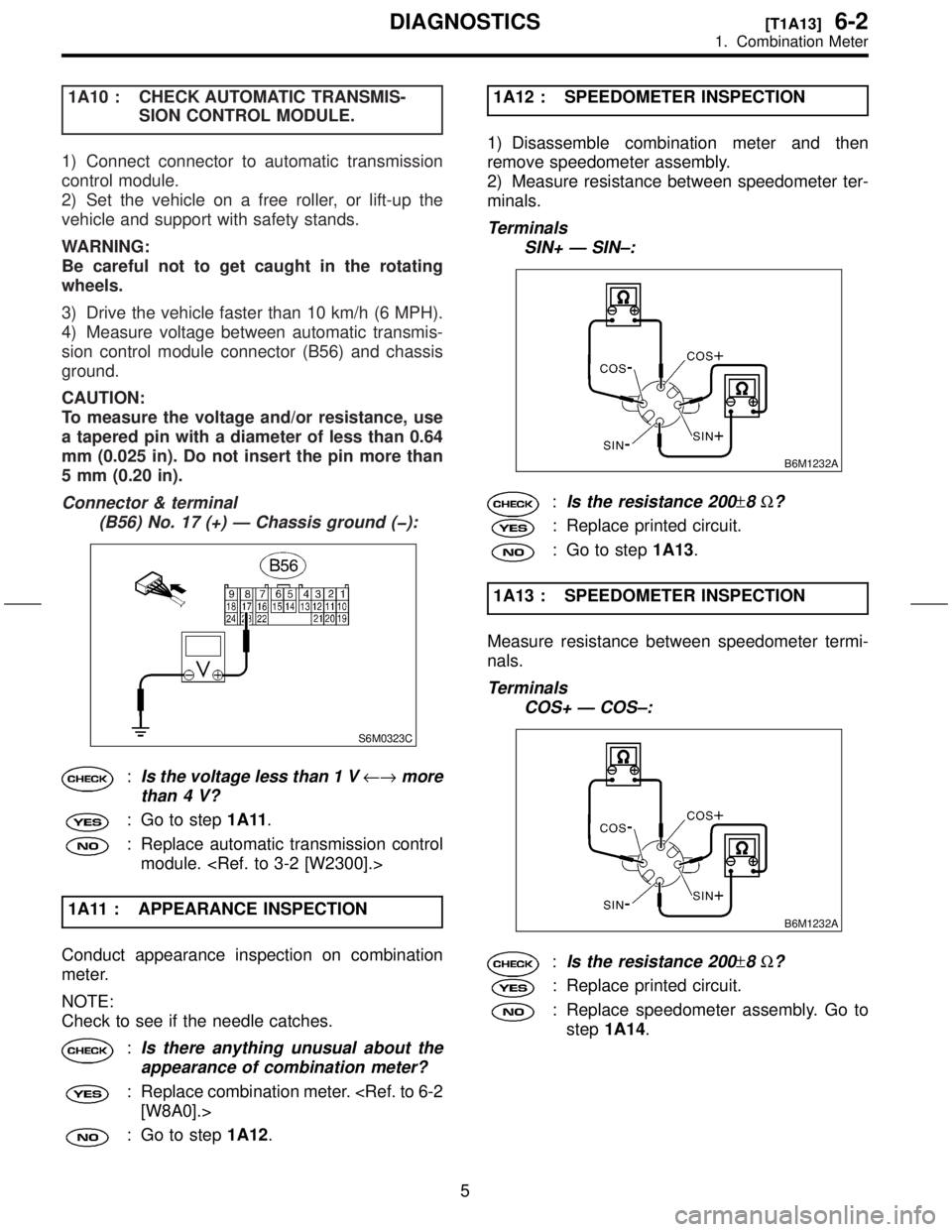
1A10 : CHECK AUTOMATIC TRANSMIS-
SION CONTROL MODULE.
1) Connect connector to automatic transmission
control module.
2) Set the vehicle on a free roller, or lift-up the
vehicle and support with safety stands.
WARNING:
Be careful not to get caught in the rotating
wheels.
3) Drive the vehicle faster than 10 km/h (6 MPH).
4) Measure voltage between automatic transmis-
sion control module connector (B56) and chassis
ground.
CAUTION:
To measure the voltage and/or resistance, use
a tapered pin with a diameter of less than 0.64
mm (0.025 in). Do not insert the pin more than
5 mm (0.20 in).
Connector & terminal
(B56) No. 17 (+) Ð Chassis ground (þ):
S6M0323C
:Is the voltage less than 1 V¨more
than 4 V?
: Go to step1A11.
: Replace automatic transmission control
module.
1A11 : APPEARANCE INSPECTION
Conduct appearance inspection on combination
meter.
NOTE:
Check to see if the needle catches.
:Is there anything unusual about the
appearance of combination meter?
: Replace combination meter.
[W8A0].>
: Go to step1A12.1A12 : SPEEDOMETER INSPECTION
1) Disassemble combination meter and then
remove speedometer assembly.
2) Measure resistance between speedometer ter-
minals.
Terminals
SIN+ Ð SIN±:
B6M1232A
:Is the resistance 200±8W?
: Replace printed circuit.
: Go to step1A13.
1A13 : SPEEDOMETER INSPECTION
Measure resistance between speedometer termi-
nals.
Terminals
COS+ Ð COS±:
B6M1232A
:Is the resistance 200±8W?
: Replace printed circuit.
: Replace speedometer assembly. Go to
step1A14.
5
[T1A13]6-2DIAGNOSTICS
1. Combination Meter
Page 317 of 345
1.
BatteryT
Capacity
Reverse
Cold
Combination Speedometer
T
Fuel
T
T
2
Charge 2
Oil 2
ABS 2
CHECK
\(Malfunction 12
HI-beam 2
Door
Seat 2
Brake 2
FWD 2
AIRBAG 2
Meter 2V\3203W
A 2
Security
Low 2
Headlight 12
Front 2V\3202
Front 1
Rear T
2
T 2V\3202
Back-up 2V\3202
License 1
High-mounted 2V\3201
Room 1
Spot 1
Luggage 1
Front 2V\3205less
Rear 2V\3204less
Front Pump
Input
2V\3203less
Rear Pump
Input
2V\3203less
Horn 12
Accessory 2
Rear
defogger Input
2
Indicator 2V\3205
Cargo 2
2
6-2[S100]SPECIFICA
1.
Page 338 of 345
1
MT
A:
1\)
2\)
3\)
to
4\)
sor
5\)
B6M1449
B:
NOTE:
IDiscard
replace
I Ensure
of
I Align
speedometer
1\)
2\)
tool.
T 5.9
\2610.5\2610.05\2610.4
3\)
4\)
2-9
18
6-2[W1SER
1