Page 186 of 345
![SUBARU FORESTER 1999 Service Repair Manual 3. RELEASE CABLE
1) Remove front grille. <Ref. to 5-1 [W12A0].>
2) Remove release cable from lock assembly.
<Ref. to 5-1 [W1A2].>
3) Remove cable clip from engine compartment.
4) While disengaging cab SUBARU FORESTER 1999 Service Repair Manual 3. RELEASE CABLE
1) Remove front grille. <Ref. to 5-1 [W12A0].>
2) Remove release cable from lock assembly.
<Ref. to 5-1 [W1A2].>
3) Remove cable clip from engine compartment.
4) While disengaging cab](/manual-img/17/57427/w960_57427-185.png)
3. RELEASE CABLE
1) Remove front grille.
2) Remove release cable from lock assembly.
3) Remove cable clip from engine compartment.
4) While disengaging cable from opener lever,
remove opener lever from front pillar.
S5M0149
5) Remove release cable.
6) Install in the reverse order of removal.
B: POINTS TO CHECK
1) Check striker for bending or abnormal wear.
2) Check safety lever for improper movement.
3) Check other levers and spring for rust formation
and rough movement.
G5M0140
C: ADJUSTMENT
1) Fore-aft and left-right adjustments
Loosen striker mounting bolts and adjust fore-and-
aft position of striker.
CAUTION:
Do not adjust striker position using the lock.
Doing so may result in a misaligned front grille.
G5M0143
2) Up-down adjustment
Make up-and-down adjustment of striker only
when hood does not properly contact buffer or
hood is not flush with fender, or when release cable
does not properly operate. Adjustment can be
made by adjusting the stroke length of the striker
after lock assembly mounting screws are removed.
30
5-1[W1A3]SERVICE PROCEDURE
1. Hood
Page 193 of 345
C: DEEP DAMAGE SUCH AS A BREAK OR HOLE THAT REQUIRES FILLING
Much of the peripheral grained surface must be sacrificed for repair, and the degree of restoration may not
be worth the expense. (The surface, however, will become almost flush with adjacent areas.)
Recommended repair kit: PP Part Repair Kit (NRM)
Process
No.Process name Job contents
1 Bumper removal Remove bumper as required.
2 Part removal Remove parts built into bumper as required.
3Bumper place-
mentPlace bumper on a paint worktable as
required.
It is recommended that contour of worktable
accommodate internal shape of bumper.
G5M0164
4Surface prepara-
tionRemove dust, oil, etc. from areas to be repaired and surrounding areas, using a suitable sol-
vent (NRM No. 900 Precleno, white gasoline, or alcohol).
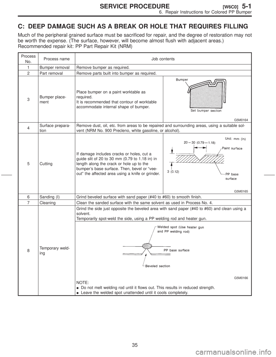
5 CuttingIf damage includes cracks or holes, cut a
guide slit of 20 to 30 mm (0.79 to 1.18 in) in
length along the crack or hole up to the
bumper's base surface. Then, bevel or ªvee-
outº the affected area using a knife or grinder.
G5M0165
6 Sanding (I) Grind beveled surface with sand paper (#40 to #60) to smooth finish.
7 Cleaning Clean the sanded surface with the same solvent as used in Process No. 4.
8Temporary weld-
ingGrind the side just opposite the beveled area with sand paper (#40 to #60) and clean using a
solvent.
Temporarily spot-weld the side, using a PP welding rod and heater gun.
G5M0166
NOTE:
IDo not melt welding rod until it flows out. This results in reduced strength.
ILeave the welded spot unattended until it cools completely.
35
[W6C0]5-1SERVICE PROCEDURE
6. Repair Instructions for Colored PP Bumper
Page 204 of 345
15. Sunroof
A: REMOVAL AND INSTALLATION
1. GLASS LID
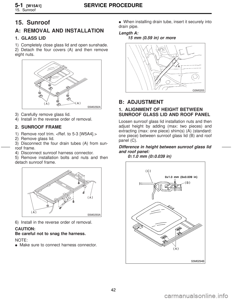
1) Completely close glass lid and open sunshade.
2) Detach the four covers (A) and then remove
eight nuts.
S5M0292A
3) Carefully remove glass lid.
4) Install in the reverse order of removal.
2. SUNROOF FRAME
1) Remove roof trim.
2) Remove glass lid.
3) Disconnect the four drain tubes (A) from sun-
roof frame.
4) Disconnect sunroof harness connector.
5) Remove installation bolts and nuts and then
detach sunroof frame.
S5M0293A
6) Install in the reverse order of removal.
CAUTION:
Be careful not to snag the harness.
NOTE:
IMake sure to connect harness connector.IWhen installing drain tube, insert it securely into
drain pipe.
Length A:
15 mm (0.59 in) or more
G5M0205
B: ADJUSTMENT
1. ALIGNMENT OF HEIGHT BETWEEN
SUNROOF GLASS LID AND ROOF PANEL
Loosen sunroof glass lid installation nuts and then
adjust height by adding (max: two pieces) and
extracting (max: one piece) shim(s) (A) (standard:
one piece) between sunroof glass lid (B) and roof
panel (C).
Difference in height between sunroof glass lid
and roof panel:
0
±1.0 mm (0±0.039 in)
S5M0294B
42
5-1[W15A1]SERVICE PROCEDURE
15. Sunroof
Page 207 of 345
2\)
right
of
the
supports
mately
of
Length:A:
S5M0331A
3\)
under
loose
side
in
NOTE:
It
the
better
crossbar
4\)
T3.7
\2610.3\2610.03\2610.22
ft-lb\)
S5M0332A
\(1\)
\(2\)
\(3\)
\(4\)
2.
NOTE:
Rear
LOAD
UTED
TRIBUTED\272
1\)
top
the
2\)
right
of
the
supports
mately
of
Length: B:
S5M0333A
3\)
under
loose
side
in
4\)
T3.7
\2610.3\2610.03\2610.22
ft-lb\)
S5M0332A
\(1\)
\(2\)
\(3\)
\(4\)
44
5-1[W16B2]SER
16.
Page 236 of 345
5. STRIKER
1) Remove rear skirt trim.
2) Remove the two bolts from striker (D) and
detach striker.
S5M0387A
3) Install in the reverse order of removal.
6. WEATHERSTRIP
1) Place weatherstrip so that its joints meet at
lower center of vehicle body, and install by insert-
ing flanged portion from below, as shown in section
AÐA in the figure.
G5M0492
2) Tap along entire length with a rubber hammer to
firmly insert body flange into weatherstrip.
CAUTION:
IBe careful not to install in wrong direction.
IInstall weatherstrip carefully and firmly.
G5M0493
28
5-2[W3A5]SERVICE PROCEDURE
3. Rear Gate
Page 300 of 345
2. YOKE
Make sure pole is set in position.
3. OVERRUNNING CLUTCH
Inspect teeth of pinion for wear and damage.
Replace if it is damaged. Rotate pinion in direction
of rotation (counterclockwise). It should rotate
smoothly. But in opposite direction, it should be
locked.
CAUTION:
Do not clean overrunning clutch with oil to pre-
vent grease from flowing out.
4. BRUSH AND BRUSH HOLDER
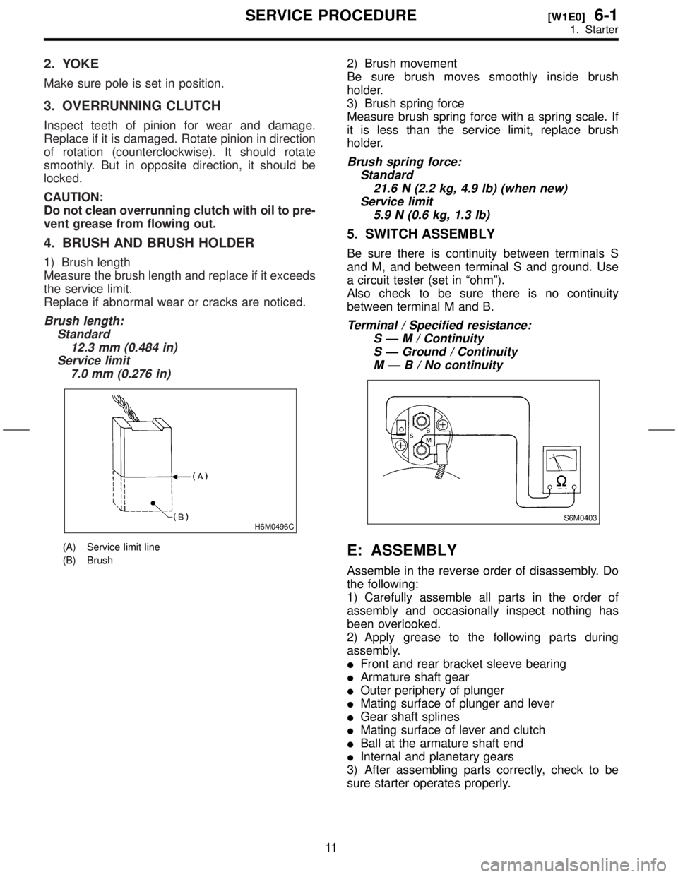
1) Brush length
Measure the brush length and replace if it exceeds
the service limit.
Replace if abnormal wear or cracks are noticed.
Brush length:
Standard
12.3 mm (0.484 in)
Service limit
7.0 mm (0.276 in)
H6M0496C
(A) Service limit line
(B) Brush
2) Brush movement
Be sure brush moves smoothly inside brush
holder.
3) Brush spring force
Measure brush spring force with a spring scale. If
it is less than the service limit, replace brush
holder.
Brush spring force:
Standard
21.6 N (2.2 kg, 4.9 lb) (when new)
Service limit
5.9 N (0.6 kg, 1.3 lb)
5. SWITCH ASSEMBLY
Be sure there is continuity between terminals S
and M, and between terminal S and ground. Use
a circuit tester (set in ªohmº).
Also check to be sure there is no continuity
between terminal M and B.
Terminal / Specified resistance:
SÐM/Continuity
S Ð Ground / Continuity
MÐB/Nocontinuity
S6M0403
E: ASSEMBLY
Assemble in the reverse order of disassembly. Do
the following:
1) Carefully assemble all parts in the order of
assembly and occasionally inspect nothing has
been overlooked.
2) Apply grease to the following parts during
assembly.
IFront and rear bracket sleeve bearing
IArmature shaft gear
IOuter periphery of plunger
IMating surface of plunger and lever
IGear shaft splines
IMating surface of lever and clutch
IBall at the armature shaft end
IInternal and planetary gears
3) After assembling parts correctly, check to be
sure starter operates properly.
11
[W1E0]6-1SERVICE PROCEDURE
1. Starter
Page 304 of 345
3. STATOR
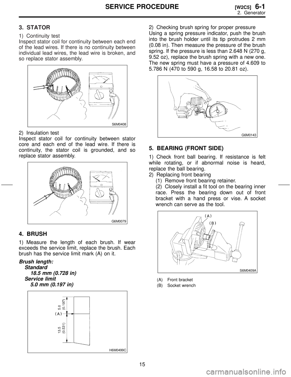
1) Continuity test
Inspect stator coil for continuity between each end
of the lead wires. If there is no continuity between
individual lead wires, the lead wire is broken, and
so replace stator assembly.
S6M0408
2) Insulation test
Inspect stator coil for continuity between stator
core and each end of the lead wire. If there is
continuity, the stator coil is grounded, and so
replace stator assembly.
G6M0079
4. BRUSH
1) Measure the length of each brush. If wear
exceeds the service limit, replace the brush. Each
brush has the service limit mark (A) on it.
Brush length:
Standard
18.5 mm (0.728 in)
Service limit
5.0 mm (0.197 in)
H6M0499C
2) Checking brush spring for proper pressure
Using a spring pressure indicator, push the brush
into the brush holder until its tip protrudes 2 mm
(0.08 in). Then measure the pressure of the brush
spring. If the pressure is less than 2.648 N (270 g,
9.52 oz), replace the brush spring with a new one.
The new spring must have a pressure of 4.609 to
5.786 N (470 to 590 g, 16.58 to 20.81 oz).
G6M0143
5. BEARING (FRONT SIDE)
1) Check front ball bearing. If resistance is felt
while rotating, or if abnormal noise is heard,
replace the ball bearing.
2) Replacing front bearing
(1) Remove front bearing retainer.
(2) Closely install a fit tool on the bearing inner
race. Press the bearing down out of front
bracket with a hand press or vise. A socket
wrench can serve as the tool.
S6M0409A
(A) Front bracket
(B) Socket wrench
15
[W2C5]6-1SERVICE PROCEDURE
2. Generator
Page 305 of 345
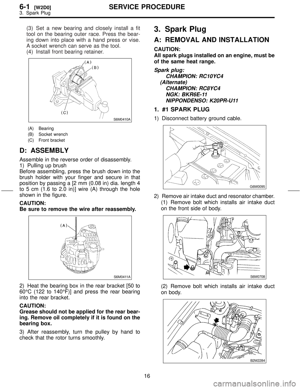
(3) Set a new bearing and closely install a fit
tool on the bearing outer race. Press the bear-
ing down into place with a hand press or vise.
A socket wrench can serve as the tool.
(4) Install front bearing retainer.
S6M0410A
(A) Bearing
(B) Socket wrench
(C) Front bracket
D: ASSEMBLY
Assemble in the reverse order of disassembly.
1) Pulling up brush
Before assembling, press the brush down into the
brush holder with your finger and secure in that
position by passing a [2 mm (0.08 in) dia. length 4
to 5 cm (1.6 to 2.0 in)] wire (A) through the hole
shown in the figure.
CAUTION:
Be sure to remove the wire after reassembly.
S6M0411A
2) Heat the bearing box in the rear bracket [50 to
60ÉC (122 to 140ÉF)] and press the rear bearing
into the rear bracket.
CAUTION:
Grease should not be applied for the rear bear-
ing. Remove oil completely if it is found on the
bearing box.
3) After reassembly, turn the pulley by hand to
check that the rotor turns smoothly.
3. Spark Plug
A: REMOVAL AND INSTALLATION
CAUTION:
All spark plugs installed on an engine, must be
of the same heat range.
Spark plug:
CHAMPION: RC10YC4
(Alternate)
CHAMPION: RC8YC4
NGK: BKR6E-11
NIPPONDENSO: K20PR-U11
1. #1 SPARK PLUG
1) Disconnect battery ground cable.
G6M0095
2) Remove air intake duct and resonator chamber.
(1) Remove bolt which installs air intake duct
on the front side of body.
S6M0708
(2) Remove bolt which installs air intake duct
on body.
B2M2284
16
6-1[W2D0]SERVICE PROCEDURE
3. Spark Plug