Page 306 of 345

(3) Set a new bearing and closely install a fit
tool on the bearing outer race. Press the bear-
ing down into place with a hand press or vise.
A socket wrench can serve as the tool.
(4) Install front bearing retainer.
S6M0410A
(A) Bearing
(B) Socket wrench
(C) Front bracket
D: ASSEMBLY
Assemble in the reverse order of disassembly.
1) Pulling up brush
Before assembling, press the brush down into the
brush holder with your finger and secure in that
position by passing a [2 mm (0.08 in) dia. length 4
to 5 cm (1.6 to 2.0 in)] wire (A) through the hole
shown in the figure.
CAUTION:
Be sure to remove the wire after reassembly.
S6M0411A
2) Heat the bearing box in the rear bracket [50 to
60ÉC (122 to 140ÉF)] and press the rear bearing
into the rear bracket.
CAUTION:
Grease should not be applied for the rear bear-
ing. Remove oil completely if it is found on the
bearing box.
3) After reassembly, turn the pulley by hand to
check that the rotor turns smoothly.
3. Spark Plug
A: REMOVAL AND INSTALLATION
CAUTION:
All spark plugs installed on an engine, must be
of the same heat range.
Spark plug:
CHAMPION: RC10YC4
(Alternate)
CHAMPION: RC8YC4
NGK: BKR6E-11
NIPPONDENSO: K20PR-U11
1. #1 SPARK PLUG
1) Disconnect battery ground cable.
G6M0095
2) Remove air intake duct and resonator chamber.
(1) Remove bolt which installs air intake duct
on the front side of body.
S6M0708
(2) Remove bolt which installs air intake duct
on body.
B2M2284
16
6-1[W2D0]SERVICE PROCEDURE
3. Spark Plug
Page 315 of 345

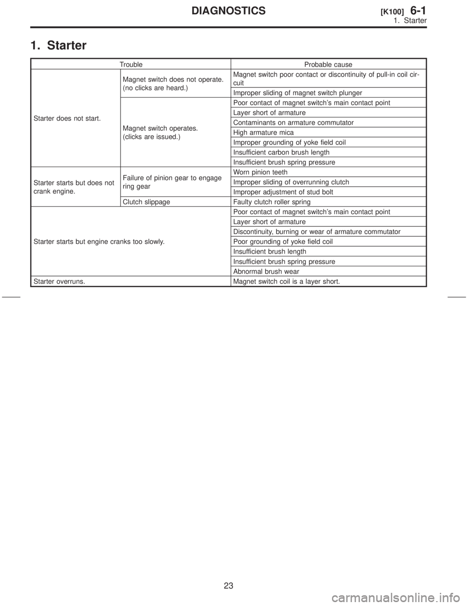
1. Starter
Trouble Probable cause
Starter does not start.Magnet switch does not operate.
(no clicks are heard.)Magnet switch poor contact or discontinuity of pull-in coil cir-
cuit
Improper sliding of magnet switch plunger
Magnet switch operates.
(clicks are issued.)Poor contact of magnet switch's main contact point
Layer short of armature
Contaminants on armature commutator
High armature mica
Improper grounding of yoke field coil
Insufficient carbon brush length
Insufficient brush spring pressure
Starter starts but does not
crank engine.Failure of pinion gear to engage
ring gearWorn pinion teeth
Improper sliding of overrunning clutch
Improper adjustment of stud bolt
Clutch slippage Faulty clutch roller spring
Starter starts but engine cranks too slowly.Poor contact of magnet switch's main contact point
Layer short of armature
Discontinuity, burning or wear of armature commutator
Poor grounding of yoke field coil
Insufficient brush length
Insufficient brush spring pressure
Abnormal brush wear
Starter overruns. Magnet switch coil is a layer short.
23
[K100]6-1DIAGNOSTICS
1. Starter
Page 334 of 345

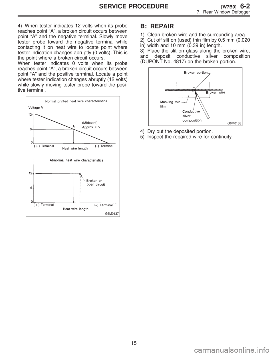
4) When tester indicates 12 volts when its probe
reaches point ªAº, a broken circuit occurs between
point ªAº and the negative terminal. Slowly move
tester probe toward the negative terminal while
contacting it on heat wire to locate point where
tester indication changes abruptly (0 volts). This is
the point where a broken circuit occurs.
When tester indicates 0 volts when its probe
reaches point ªAº, a broken circuit occurs between
point ªAº and the positive terminal. Locate a point
where tester indication changes abruptly (12 volts)
while slowly moving tester probe toward the posi-
tive terminal.
G6M0137
B: REPAIR
1) Clean broken wire and the surrounding area.
2) Cut off slit on (used) thin film by 0.5 mm (0.020
in) width and 10 mm (0.39 in) length.
3) Place the slit on glass along the broken wire,
and deposit conductive silver composition
(DUPONT No. 4817) on the broken portion.
G6M0138
4) Dry out the deposited portion.
5) Inspect the repaired wire for continuity.
15
[W7B0]6-2SERVICE PROCEDURE
7. Rear Window Defogger