1999 SUBARU FORESTER engine
[x] Cancel search: enginePage 10 of 345
4. Diagnostics Chart for On-
board Diagnostic System
A: BASIC DIAGNOSTICS
PROCEDURE
4A1 : CHECK AIRBAG WARNING LIGHT
ILLUMINATES.
1) Turn ignition switch to ON (engine OFF).
2) Check airbag warning light illuminates.
:Does airbag warning light stay ON
after about 7 seconds or remain OFF,
or come back ON after 30 seconds?
: Repair and replace.
: Go to step4A2.
4A2 : CHECK TROUBLE CODE INDICATES.
Perform ON-BOARD DIAGNOSTICS.
:Does trouble code indicate?
: Repair and replace.
: Repair and replace.
4A3 : CHECK AIRBAG WARNING LIGHT
ILLUMINATES.
1) Turn ignition switch to ON (engine OFF).
2) Check airbag warning light illuminates.
:Does airbag warning light stay ON
after about 7 seconds or come back
ON after 30 seconds?
: Repair and replace.
: Go to step4A4.4A4 : CHECK AIRBAG WARNING LIGHT
ILLUMINATES.
Check airbag warning light illuminates.
:Does airbag warning light come ON
for about 7 seconds, then go out and
stay out?
: Perform clear memory.
: Go to step4A1.
B: ON-BOARD DIAGNOSTIC
When the airbag system is in functioning condition,
the airbag warning light will remain on for about 7
seconds and go out when the ignition switch is set
to ON.
If there is any malfunction, the airbag warning light
will either stay on or off continuously. In such
cases, perform on-board diagnostic in accordance
with the specified procedure to determine trouble
codes.
1) Turn ignition switch ON (with engine OFF).
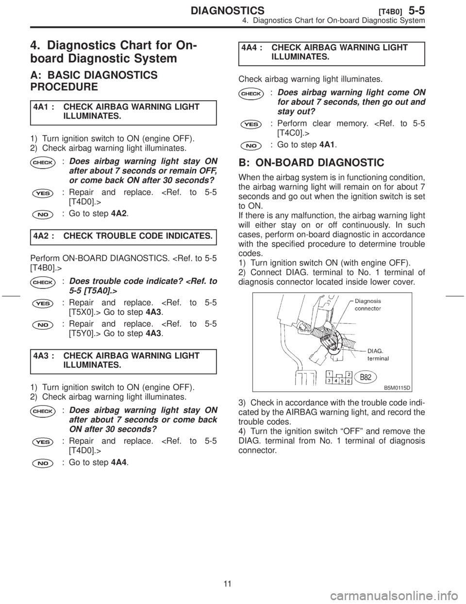
2) Connect DIAG. terminal to No. 1 terminal of
diagnosis connector located inside lower cover.
B5M0115D
3) Check in accordance with the trouble code indi-
cated by the AIRBAG warning light, and record the
trouble codes.
4) Turn the ignition switch ªOFFº and remove the
DIAG. terminal from No. 1 terminal of diagnosis
connector.
11
[T4B0]5-5DIAGNOSTICS
4. Diagnostics Chart for On-board Diagnostic System
Page 11 of 345
C: CLEAR MEMORY
After eliminating problem as per trouble code, clear
memory as follows:
1) Make sure ignition switch is ON (and engine
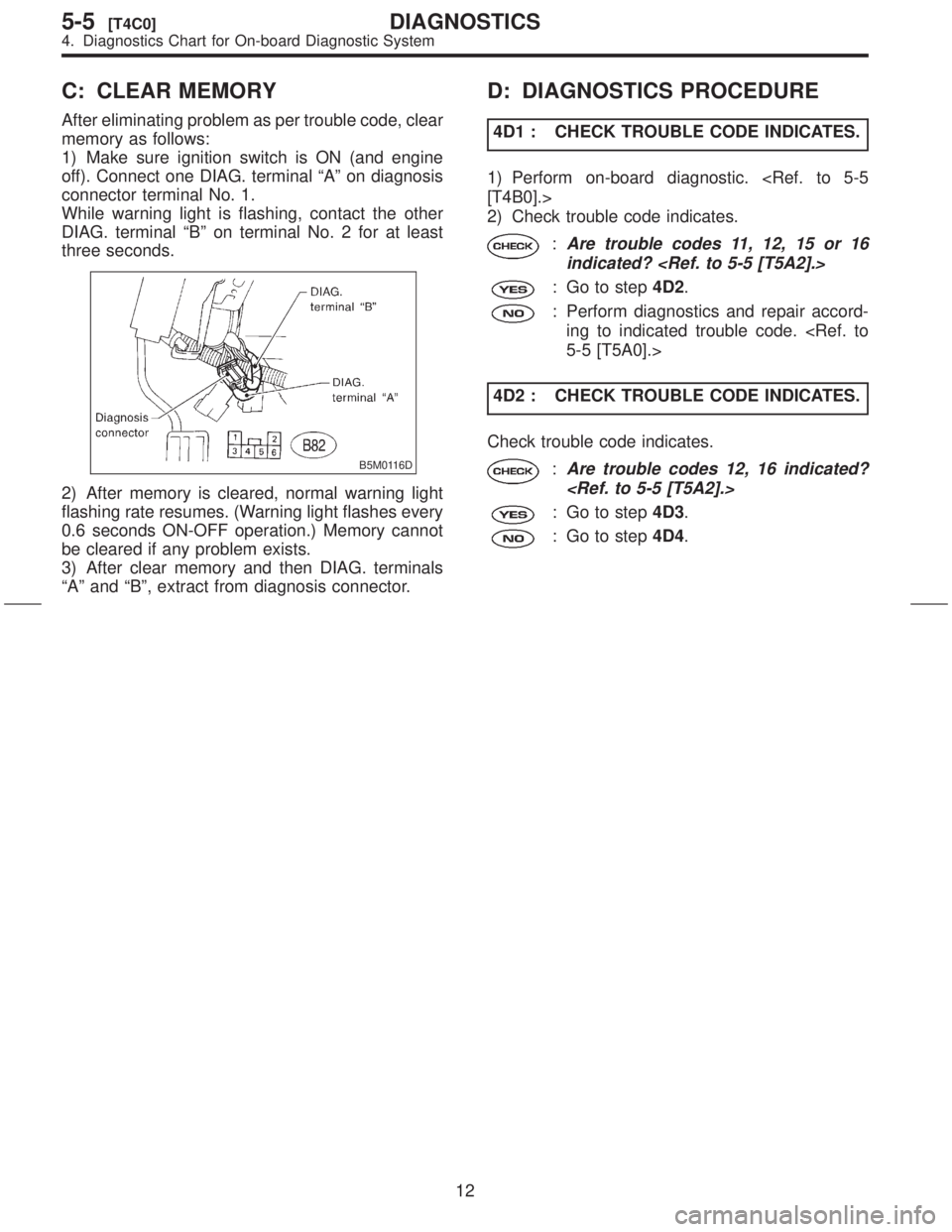
off). Connect one DIAG. terminal ªAº on diagnosis
connector terminal No. 1.
While warning light is flashing, contact the other
DIAG. terminal ªBº on terminal No. 2 for at least
three seconds.
B5M0116D
2) After memory is cleared, normal warning light
flashing rate resumes. (Warning light flashes every
0.6 seconds ON-OFF operation.) Memory cannot
be cleared if any problem exists.
3) After clear memory and then DIAG. terminals
ªAº and ªBº, extract from diagnosis connector.
D: DIAGNOSTICS PROCEDURE
4D1 : CHECK TROUBLE CODE INDICATES.
1) Perform on-board diagnostic.
2) Check trouble code indicates.
:Are trouble codes 11, 12, 15 or 16
indicated?
: Go to step4D2.
: Perform diagnostics and repair accord-
ing to indicated trouble code.
4D2 : CHECK TROUBLE CODE INDICATES.
Check trouble code indicates.
:Are trouble codes 12, 16 indicated?
: Go to step4D3.
: Go to step4D4.
12
5-5[T4C0]DIAGNOSTICS
4. Diagnostics Chart for On-board Diagnostic System
Page 19 of 345
![SUBARU FORESTER 1999 Service Repair Manual 5C4 : AIRBAG MAIN HARNESS INSPEC-
TION
1) Disconnect connector (AB6) from airbag control
module <Ref. to 5-5 [W6A0].>, and connect it to
test harness I or I2 connector (1I).
2) Measure resistance betw SUBARU FORESTER 1999 Service Repair Manual 5C4 : AIRBAG MAIN HARNESS INSPEC-
TION
1) Disconnect connector (AB6) from airbag control
module <Ref. to 5-5 [W6A0].>, and connect it to
test harness I or I2 connector (1I).
2) Measure resistance betw](/manual-img/17/57427/w960_57427-18.png)
5C4 : AIRBAG MAIN HARNESS INSPEC-
TION
1) Disconnect connector (AB6) from airbag control
module
test harness I or I2 connector (1I).
2) Measure resistance between test harness I or
I2 connector (2I) terminals and chassis ground.
Connector & terminal
(2I) No. 2 (+) Ð Chassis ground (þ):
S5M0278B
:Is resistance more than 1 MW?
: Go to step5C5.
: Replace airbag main harness.
5C5 : AIRBAG MAIN HARNESS INSPEC-
TION
Measure resistance between test harness I or I2
connector (2I) terminals and chassis ground.
Connector & terminal
(2I) No. 5 (+) Ð Chassis ground (þ):
S5M0279B
:Is resistance more than 1 MW?
: Replace airbag control module.
: Replace airbag main harness.
D: TROUBLE CODE 15
DIAGNOSIS:
IAirbag main harness circuit (Driver) is shorted to
power supply.
IAirbag module harness (Driver) is shorted to
power supply.
IRoll connector is shorted to power supply.
IAirbag control module is faulty.
CAUTION:
Before performing diagnostics on airbag
system, turn ignition switch ªOFFº, disconnect
battery ground terminal and then wait at least
20 seconds.
After 20 seconds elapse, remove instrument
panel lower cover, and disconnect (AB3) and
(AB8), (AB9) and (AB10).
5D1 : AIRBAG MAIN HARNESS INSPEC-
TION
1) Disconnect connector (AB6) from airbag control
module
test harness I or I2 connector (1I).
2) Connect battery ground cable and turn ignition
switch ªONº (engine off).
3) Measure voltage across each test harness I or
I2 connector (2I) terminal and chassis ground.
Connector & terminal
(2I) No. 4 (+) Ð Chassis ground (þ):
S5M0280B
:Is voltage less than 1 V?
: Go to step5D2.
: Replace airbag main harness.
20
5-5[T5C4]DIAGNOSTICS
5. Diagnostics Chart with Trouble Code
Page 20 of 345
5D2 : AIRBAG MAIN HARNESS INSPEC-
TION
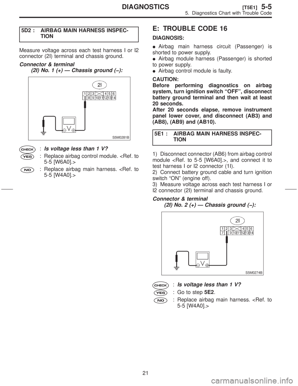
Measure voltage across each test harness I or I2
connector (2I) terminal and chassis ground.
Connector & terminal
(2I) No. 1 (+) Ð Chassis ground (þ):
S5M0281B
:Is voltage less than 1 V?
: Replace airbag control module.
: Replace airbag main harness.
E: TROUBLE CODE 16
DIAGNOSIS:
IAirbag main harness circuit (Passenger) is
shorted to power supply.
IAirbag module harness (Passenger) is shorted
to power supply.
IAirbag control module is faulty.
CAUTION:
Before performing diagnostics on airbag
system, turn ignition switch ªOFFº, disconnect
battery ground terminal and then wait at least
20 seconds.
After 20 seconds elapse, remove instrument
panel lower cover, and disconnect (AB3) and
(AB8), (AB9) and (AB10).
5E1 : AIRBAG MAIN HARNESS INSPEC-
TION
1) Disconnect connector (AB6) from airbag control
module
test harness I or I2 connector (1I).
2) Connect battery ground cable and turn ignition
switch ªONº (engine off).
3) Measure voltage across each test harness I or
I2 connector (2I) terminal and chassis ground.
Connector & terminal
(2I) No. 2 (+) Ð Chassis ground (þ):
S5M0274B
:Is voltage less than 1 V?
: Go to step5E2.
: Replace airbag main harness.
21
[T5E1]5-5DIAGNOSTICS
5. Diagnostics Chart with Trouble Code
Page 23 of 345
I: TROUBLE CODE 24
DIAGNOSIS:
IAirbag control module is faulty.
IAirbag main harness circuit is open.
IFuse No. 11 (in joint box) is blown.
IBody harness circuit is open.
CAUTION:
Before performing diagnostics on airbag
system, turn ignition switch ªOFFº, disconnect
battery ground cable and then wait at least 20
seconds.
After 20 seconds elapse, remove instrument
panel lower cover, and disconnect (AB3) and
(AB8), (AB9) and (AB10).
5I1 : AIRBAG CONTROL MODULE INSPEC-
TION
1) Disconnect connector (AB6) from airbag control
module
test harness I or I2 connector (1I).
2) Connect battery ground cable and turn ignition
switch ªONº (engine off).
3) Measure voltage across connector (2I) terminal
and chassis ground.
Connector & terminal
(2I) No. 3 (+) Ð Chassis ground (þ):
S5M0264B
:Is voltage more than 10 V?
: Replace airbag control module.
: Go to step5I2.5I2 : AIRBAG MAIN HARNESS INSPEC-
TION
1) Go to following procedure after performing
diagnostics on airbag system as per diagnosis pro-
cedure under ª5I1 AIRBAG CONTROL MODULE
INSPECTIONº
lined.
2) Turn ignition switch ªOFFº, disconnect battery
ground cable and then wait at least 20 seconds.
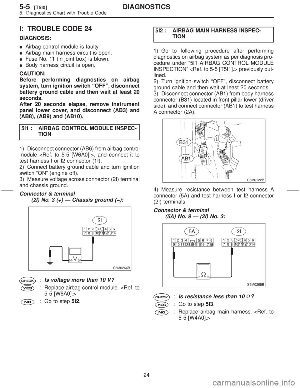
3) Disconnect connector (AB1) from body harness
connector (B31) located in front pillar lower (driver
side), and connect connector (AB1) to test harness
A connector (2A).
B5M0122B
4) Measure resistance between test harness A
connector (5A) and test harness I or I2 connector
(2I) terminals.
Connector & terminal
(5A) No. 9 Ð (2I) No. 3:
S5M0265B
:Is resistance less than 10W?
: Go to step5I3.
: Replace airbag main harness.
24
5-5[T5I0]DIAGNOSTICS
5. Diagnostics Chart with Trouble Code
Page 25 of 345
J: TROUBLE CODE 25
DIAGNOSIS:
IAirbag control module is faulty.
IAirbag main harness circuit is open.
IFuse No. 6 (in joint box) is blown.
IBody harness circuit is open.
CAUTION:
Before performing diagnostics on airbag
system, turn ignition switch ªOFFº, disconnect
battery ground cable and then wait at least 20
seconds.
After 20 seconds elapse, remove instrument
panel lower cover, and disconnect (AB3) and
(AB8), (AB9) and (AB10).
5J1 : AIRBAG CONTROL MODULE
INSPECTION
1) Disconnect connector (AB6) from airbag control
module
harness I or I2 connector (1I).
2) Connect battery ground cable and turn ignition
switch ªONº. (engine off)
3) Measure voltage across connector (2I) terminal
and chassis ground.
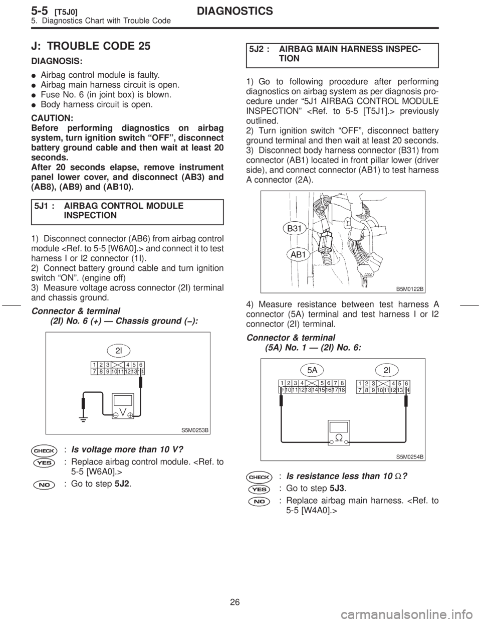
Connector & terminal
(2I) No. 6 (+) Ð Chassis ground (þ):
S5M0253B
:Is voltage more than 10 V?
: Replace airbag control module.
: Go to step5J2.5J2 : AIRBAG MAIN HARNESS INSPEC-
TION
1) Go to following procedure after performing
diagnostics on airbag system as per diagnosis pro-
cedure under ª5J1 AIRBAG CONTROL MODULE
INSPECTIONº
outlined.
2) Turn ignition switch ªOFFº, disconnect battery
ground terminal and then wait at least 20 seconds.
3) Disconnect body harness connector (B31) from
connector (AB1) located in front pillar lower (driver
side), and connect connector (AB1) to test harness
A connector (2A).
B5M0122B
4) Measure resistance between test harness A
connector (5A) terminal and test harness I or I2
connector (2I) terminal.
Connector & terminal
(5A) No. 1 Ð (2I) No. 6:
S5M0254B
:Is resistance less than 10W?
: Go to step5J3.
: Replace airbag main harness.
26
5-5[T5J0]DIAGNOSTICS
5. Diagnostics Chart with Trouble Code
Page 42 of 345
O: TROUBLE CODE 45
DIAGNOSIS:
ISide airbag harness (RH) is faulty.
IAirbag control module is faulty.
CAUTION:
Before performing diagnostics on airbag
system, turn ignition switch ªOFFº, disconnect
battery ground cable and then wait at least 20
seconds.
5O1 : SIDE AIRBAG MODULE INSPECTION
1) Disconnect connector (AB24) and (AB25), and
then connect connector (AB24) and test harness F
connector (1F).
2) Connect test harness F connector (3F) and air-
bag resistor
3) Connect battery ground cable and then turn
ignition switch ON.
:Does the airbag warning light go off
after about 7 seconds and remain off
for more than 30 seconds?
: Replace front seat with side airbag mod-
ule (RH).
: Go to step5O2.5O2 : SIDE AIRBAG HARNESS (RH)
INSPECTION
1) Turn ignition switch OFF, disconnect battery
ground cable and then wait at least 20 seconds.
2) Disconnect test harness F and airbag resistor.
3) Disconnect connector (AB18) from airbag con-
trol module and connect it to test harness I or I2
connector (1I).
4) Connect battery ground cable and turn ignition
switch ON. (engine off)
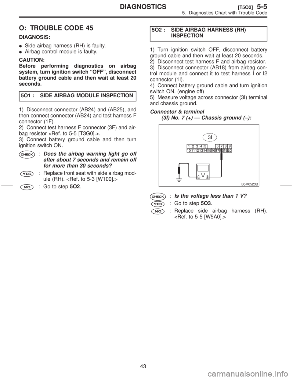
5) Measure voltage across connector (3I) terminal
and chassis ground.
Connector & terminal
(3I) No. 7 (+) Ð Chassis ground (±):
B5M0523B
:Is the voltage less than 1 V?
: Go to step5O3.
: Replace side airbag harness (RH).
43
[T5O2]5-5DIAGNOSTICS
5. Diagnostics Chart with Trouble Code
Page 44 of 345
5P2 : SIDE AIRBAG HARNESS (LH)
INSPECTION
1) Turn ignition switch OFF, disconnect battery
ground cable and then wait at least 20 seconds.
2) Disconnect test harness F and airbag resistor.
3) Disconnect connector (AB17) from airbag con-
trol module and connect it to test harness I or I2
connector (1I).
4) Connect battery ground cable and turn ignition
switch ON. (engine off)
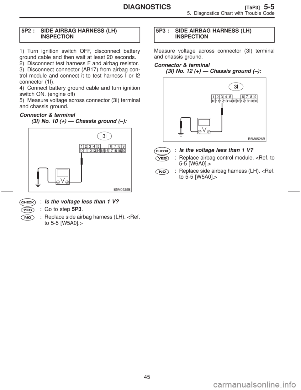
5) Measure voltage across connector (3I) terminal
and chassis ground.
Connector & terminal
(3I) No. 10 (+) Ð Chassis ground (±):
B5M0525B
:Is the voltage less than 1 V?
: Go to step5P3.
: Replace side airbag harness (LH).
INSPECTION
Measure voltage across connector (3I) terminal
and chassis ground.
Connector & terminal
(3I) No. 12 (+) Ð Chassis ground (±):
B5M0526B
:Is the voltage less than 1 V?
: Replace airbag control module.
: Replace side airbag harness (LH).
45
[T5P3]5-5DIAGNOSTICS
5. Diagnostics Chart with Trouble Code