1999 SUBARU FORESTER engine
[x] Cancel search: enginePage 82 of 345
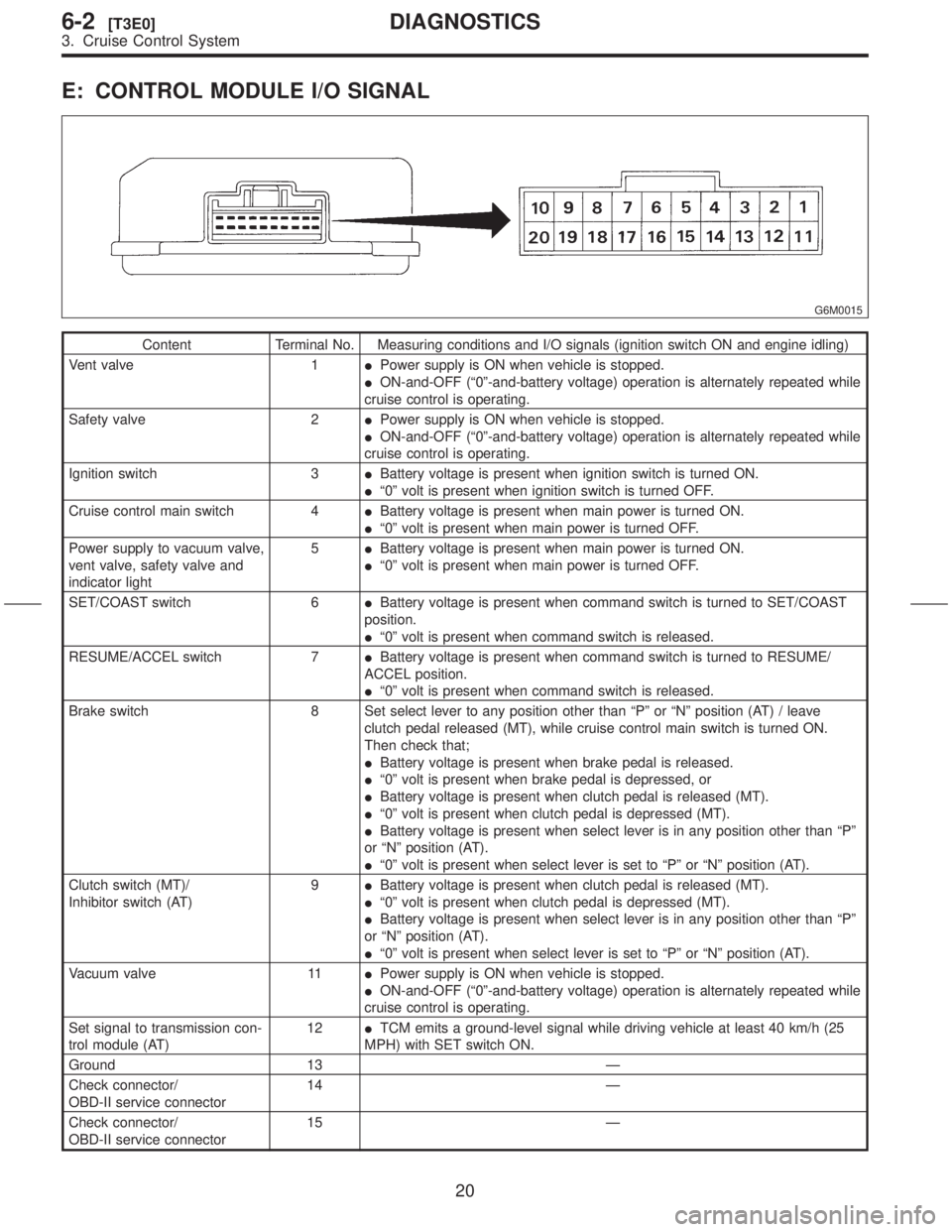
E: CONTROL MODULE I/O SIGNAL
G6M0015
Content Terminal No. Measuring conditions and I/O signals (ignition switch ON and engine idling)
Vent valve 1IPower supply is ON when vehicle is stopped.
ION-and-OFF (ª0º-and-battery voltage) operation is alternately repeated while
cruise control is operating.
Safety valve 2IPower supply is ON when vehicle is stopped.
ION-and-OFF (ª0º-and-battery voltage) operation is alternately repeated while
cruise control is operating.
Ignition switch 3IBattery voltage is present when ignition switch is turned ON.
Iª0º volt is present when ignition switch is turned OFF.
Cruise control main switch 4IBattery voltage is present when main power is turned ON.
Iª0º volt is present when main power is turned OFF.
Power supply to vacuum valve,
vent valve, safety valve and
indicator light5IBattery voltage is present when main power is turned ON.
Iª0º volt is present when main power is turned OFF.
SET/COAST switch 6IBattery voltage is present when command switch is turned to SET/COAST
position.
Iª0º volt is present when command switch is released.
RESUME/ACCEL switch 7IBattery voltage is present when command switch is turned to RESUME/
ACCEL position.
Iª0º volt is present when command switch is released.
Brake switch 8 Set select lever to any position other than ªPº or ªNº position (AT) / leave
clutch pedal released (MT), while cruise control main switch is turned ON.
Then check that;
IBattery voltage is present when brake pedal is released.
Iª0º volt is present when brake pedal is depressed, or
IBattery voltage is present when clutch pedal is released (MT).
Iª0º volt is present when clutch pedal is depressed (MT).
IBattery voltage is present when select lever is in any position other than ªPº
or ªNº position (AT).
Iª0º volt is present when select lever is set to ªPº or ªNº position (AT).
Clutch switch (MT)/
Inhibitor switch (AT)9IBattery voltage is present when clutch pedal is released (MT).
Iª0º volt is present when clutch pedal is depressed (MT).
IBattery voltage is present when select lever is in any position other than ªPº
or ªNº position (AT).
Iª0º volt is present when select lever is set to ªPº or ªNº position (AT).
Vacuum valve 11IPower supply is ON when vehicle is stopped.
ION-and-OFF (ª0º-and-battery voltage) operation is alternately repeated while
cruise control is operating.
Set signal to transmission con-
trol module (AT)12ITCM emits a ground-level signal while driving vehicle at least 40 km/h (25
MPH) with SET switch ON.
Ground 13 Ð
Check connector/
OBD-II service connector14 Ð
Check connector/
OBD-II service connector15 Ð
20
6-2[T3E0]DIAGNOSTICS
3. Cruise Control System
Page 83 of 345

Content Terminal No. Measuring conditions and I/O signals (ignition switch ON and engine idling)
Vehicle speed sensor (MT)
Automatic transmission control
module (AT)18 Lift-up the vehicle until all four wheels are raised off ground, and then rotate
any wheel manually. Approx. 5 and 0 volt pulse signals are alternately input to
cruise control module.
Stop light switch 19 Turn ignition switch to OFF. Then check that;
IBattery voltage is present when brake pedal is depressed.
Iª0º volt is present when brake pedal is released.
Ground 20 Ð
NOTE:
Voltage at terminals 1, 2, 11 and 12 cannot be checked unless vehicle is driving by cruise control operation.
21
[T3E0]6-2DIAGNOSTICS
3. Cruise Control System
Page 85 of 345
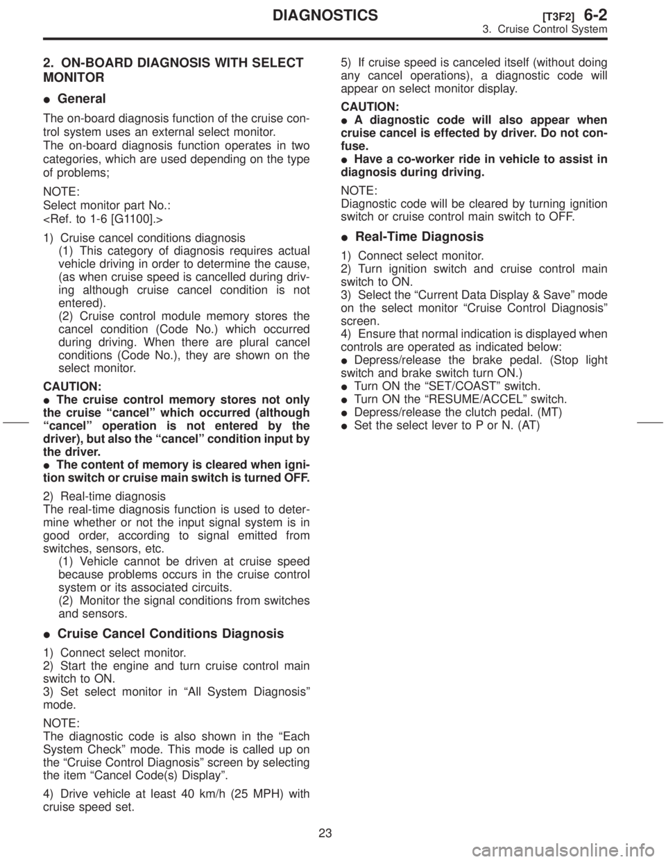
2. ON-BOARD DIAGNOSIS WITH SELECT
MONITOR
IGeneral
The on-board diagnosis function of the cruise con-
trol system uses an external select monitor.
The on-board diagnosis function operates in two
categories, which are used depending on the type
of problems;
NOTE:
Select monitor part No.:
1) Cruise cancel conditions diagnosis
(1) This category of diagnosis requires actual
vehicle driving in order to determine the cause,
(as when cruise speed is cancelled during driv-
ing although cruise cancel condition is not
entered).
(2) Cruise control module memory stores the
cancel condition (Code No.) which occurred
during driving. When there are plural cancel
conditions (Code No.), they are shown on the
select monitor.
CAUTION:
IThe cruise control memory stores not only
the cruise ªcancelº which occurred (although
ªcancelº operation is not entered by the
driver), but also the ªcancelº condition input by
the driver.
IThe content of memory is cleared when igni-
tion switch or cruise main switch is turned OFF.
2) Real-time diagnosis
The real-time diagnosis function is used to deter-
mine whether or not the input signal system is in
good order, according to signal emitted from
switches, sensors, etc.
(1) Vehicle cannot be driven at cruise speed
because problems occurs in the cruise control
system or its associated circuits.
(2) Monitor the signal conditions from switches
and sensors.
ICruise Cancel Conditions Diagnosis
1) Connect select monitor.
2) Start the engine and turn cruise control main
switch to ON.
3) Set select monitor in ªAll System Diagnosisº
mode.
NOTE:
The diagnostic code is also shown in the ªEach
System Checkº mode. This mode is called up on
the ªCruise Control Diagnosisº screen by selecting
the item ªCancel Code(s) Displayº.
4) Drive vehicle at least 40 km/h (25 MPH) with
cruise speed set.5) If cruise speed is canceled itself (without doing
any cancel operations), a diagnostic code will
appear on select monitor display.
CAUTION:
IA diagnostic code will also appear when
cruise cancel is effected by driver. Do not con-
fuse.
IHave a co-worker ride in vehicle to assist in
diagnosis during driving.
NOTE:
Diagnostic code will be cleared by turning ignition
switch or cruise control main switch to OFF.
IReal-Time Diagnosis
1) Connect select monitor.
2) Turn ignition switch and cruise control main
switch to ON.
3) Select the ªCurrent Data Display & Saveº mode
on the select monitor ªCruise Control Diagnosisº
screen.
4) Ensure that normal indication is displayed when
controls are operated as indicated below:
IDepress/release the brake pedal. (Stop light
switch and brake switch turn ON.)
ITurn ON the ªSET/COASTº switch.
ITurn ON the ªRESUME/ACCELº switch.
IDepress/release the clutch pedal. (MT)
ISet the select lever to P or N. (AT)
23
[T3F2]6-2DIAGNOSTICS
3. Cruise Control System
Page 101 of 345
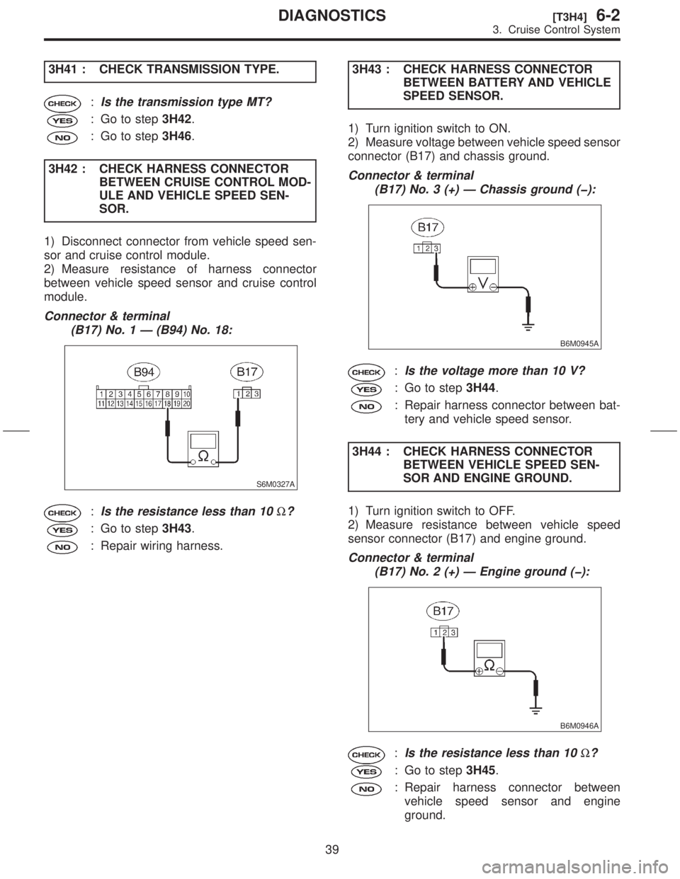
3H41 : CHECK TRANSMISSION TYPE.
:Is the transmission type MT?
: Go to step3H42.
: Go to step3H46.
3H42 : CHECK HARNESS CONNECTOR
BETWEEN CRUISE CONTROL MOD-
ULE AND VEHICLE SPEED SEN-
SOR.
1) Disconnect connector from vehicle speed sen-
sor and cruise control module.
2) Measure resistance of harness connector
between vehicle speed sensor and cruise control
module.
Connector & terminal
(B17) No. 1 Ð (B94) No. 18:
S6M0327A
:Is the resistance less than 10W?
: Go to step3H43.
: Repair wiring harness.3H43 : CHECK HARNESS CONNECTOR
BETWEEN BATTERY AND VEHICLE
SPEED SENSOR.
1) Turn ignition switch to ON.
2) Measure voltage between vehicle speed sensor
connector (B17) and chassis ground.
Connector & terminal
(B17) No. 3 (+) Ð Chassis ground (þ):
B6M0945A
:Is the voltage more than 10 V?
: Go to step3H44.
: Repair harness connector between bat-
tery and vehicle speed sensor.
3H44 : CHECK HARNESS CONNECTOR
BETWEEN VEHICLE SPEED SEN-
SOR AND ENGINE GROUND.
1) Turn ignition switch to OFF.
2) Measure resistance between vehicle speed
sensor connector (B17) and engine ground.
Connector & terminal
(B17) No. 2 (+) Ð Engine ground (þ):
B6M0946A
:Is the resistance less than 10W?
: Go to step3H45.
: Repair harness connector between
vehicle speed sensor and engine
ground.
39
[T3H4]6-2DIAGNOSTICS
3. Cruise Control System
Page 124 of 345
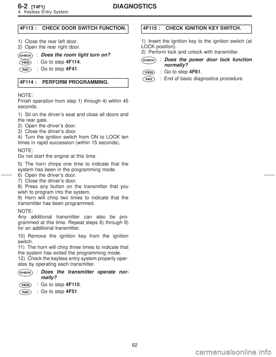
4F113 : CHECK DOOR SWITCH FUNCTION.
1) Close the rear left door.
2) Open the rear right door.
:Does the room light turn on?
: Go to step4F114.
: Go to step4F41.
4F114 : PERFORM PROGRAMMING.
NOTE:
Finish operation from step 1) through 4) within 45
seconds.
1) Sit on the driver's seat and close all doors and
the rear gate.
2) Open the driver's door.
3) Close the driver's door.
4) Turn the ignition switch from ON to LOCK ten
times in rapid succession (within 15 seconds).
NOTE:
Do not start the engine at this time.
5) The horn chirps one time to indicate that the
system has been in the programming mode.
6) Open the driver's door.
7) Close the driver's door.
8) Press any button on the transmitter that you
wish to program into the system.
9) Horn will chirp two times to indicate that the
transmitter has been programmed.
NOTE:
Any additional transmitter can also be pro-
grammed at this time. Repeat steps 6) through 9)
for an additional transmitter.
10) Remove the ignition key from the ignition
switch.
11) The horn will chirp three times to indicate that
the system has exited the programming mode.
12) Check the keyless entry system properly oper-
ates by operating each transmitter.
:Does the transmitter operate nor-
mally?
: Go to step4F115.
: Go to step4F51.4F115 : CHECK IGNITION KEY SWITCH.
1) Insert the ignition key to the ignition switch (at
LOCK position).
2) Perform lock and unlock with transmitter.
:Does the power door lock function
normally?
: Go to step4F61.
: End of basic diagnostics procedure.
62
6-2[T4F1]DIAGNOSTICS
4. Keyless Entry System
Page 146 of 345
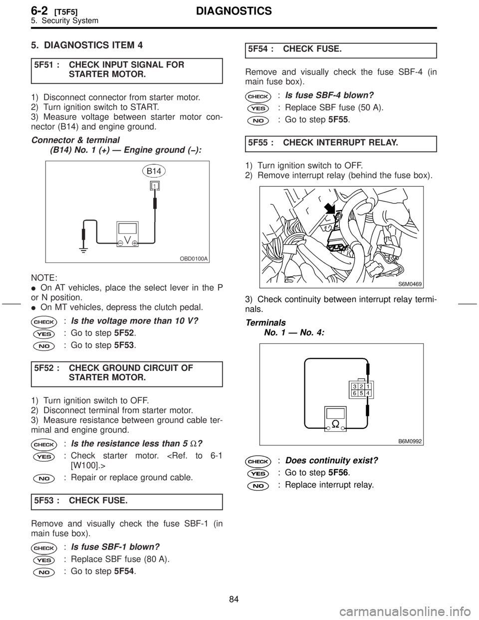
5. DIAGNOSTICS ITEM 4
5F51 : CHECK INPUT SIGNAL FOR
STARTER MOTOR.
1) Disconnect connector from starter motor.
2) Turn ignition switch to START.
3) Measure voltage between starter motor con-
nector (B14) and engine ground.
Connector & terminal
(B14) No. 1 (+) Ð Engine ground (þ):
OBD0100A
NOTE:
IOn AT vehicles, place the select lever in the P
or N position.
IOn MT vehicles, depress the clutch pedal.
:Is the voltage more than 10 V?
: Go to step5F52.
: Go to step5F53.
5F52 : CHECK GROUND CIRCUIT OF
STARTER MOTOR.
1) Turn ignition switch to OFF.
2) Disconnect terminal from starter motor.
3) Measure resistance between ground cable ter-
minal and engine ground.
:Is the resistance less than 5W?
: Check starter motor.
: Repair or replace ground cable.
5F53 : CHECK FUSE.
Remove and visually check the fuse SBF-1 (in
main fuse box).
:Is fuse SBF-1 blown?
: Replace SBF fuse (80 A).
: Go to step5F54.5F54 : CHECK FUSE.
Remove and visually check the fuse SBF-4 (in
main fuse box).
:Is fuse SBF-4 blown?
: Replace SBF fuse (50 A).
: Go to step5F55.
5F55 : CHECK INTERRUPT RELAY.
1) Turn ignition switch to OFF.
2) Remove interrupt relay (behind the fuse box).
S6M0469
3) Check continuity between interrupt relay termi-
nals.
Terminals
No. 1 Ð No. 4:
B6M0992
:Does continuity exist?
: Go to step5F56.
: Replace interrupt relay.
84
6-2[T5F5]DIAGNOSTICS
5. Security System
Page 157 of 345
1. Precaution
A: SUPPLEMENTAL RESTRAINT
SYSTEM ªAIRBAGº
Airbag system wiring harness is routed on and
along body panels.
CAUTION:
IAll airbag system wiring harness and con-
nectors are yellow. Do not use electrical test
equipment on these circuit.
IBe careful not to damage airbag system wir-
ing harness when repairing the body panel.
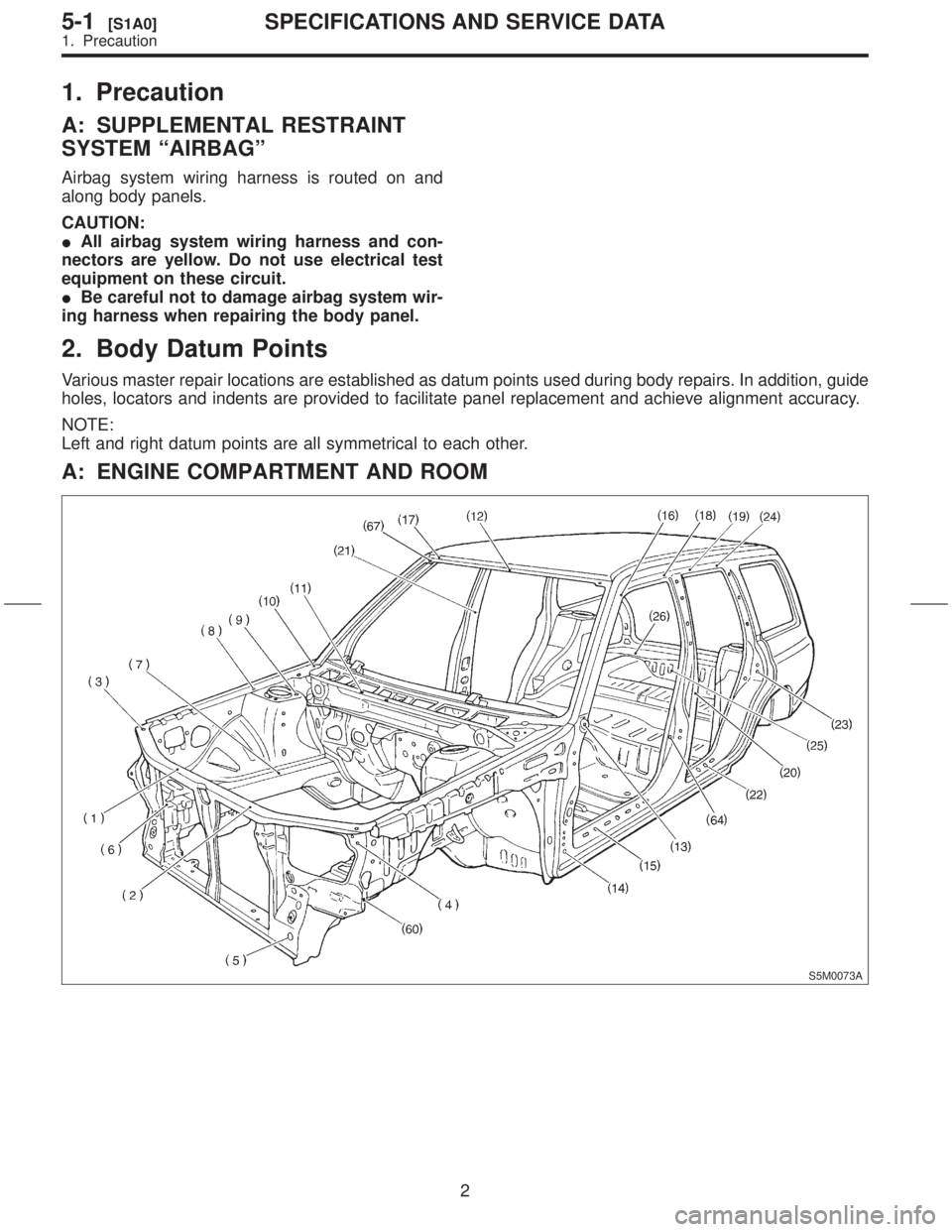
2. Body Datum Points
Various master repair locations are established as datum points used during body repairs. In addition, guide
holes, locators and indents are provided to facilitate panel replacement and achieve alignment accuracy.
NOTE:
Left and right datum points are all symmetrical to each other.
A: ENGINE COMPARTMENT AND ROOM
S5M0073A
2
5-1[S1A0]SPECIFICATIONS AND SERVICE DATA
1. Precaution
Page 158 of 345
1. Precaution
A: SUPPLEMENTAL RESTRAINT
SYSTEM ªAIRBAGº
Airbag system wiring harness is routed on and
along body panels.
CAUTION:
IAll airbag system wiring harness and con-
nectors are yellow. Do not use electrical test
equipment on these circuit.
IBe careful not to damage airbag system wir-
ing harness when repairing the body panel.
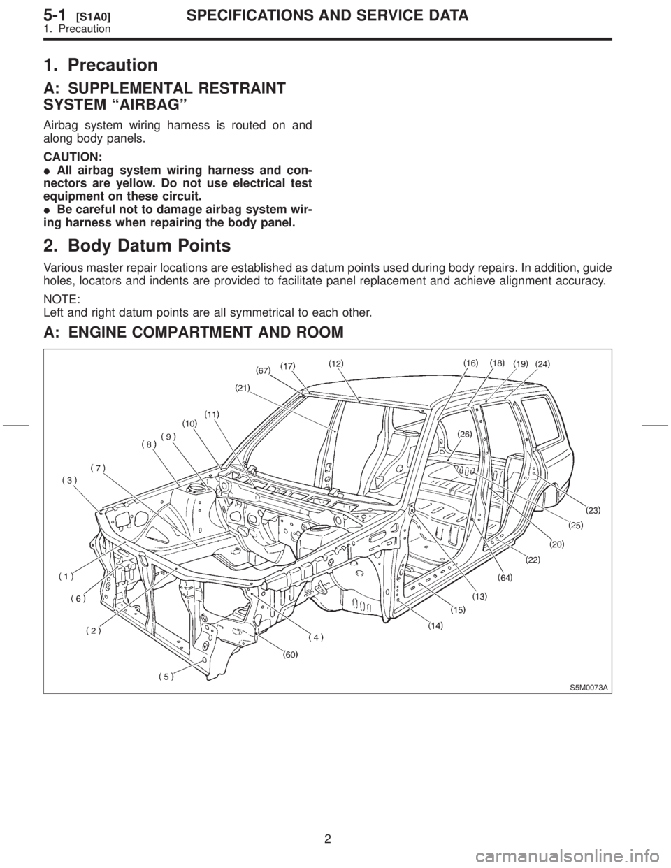
2. Body Datum Points
Various master repair locations are established as datum points used during body repairs. In addition, guide
holes, locators and indents are provided to facilitate panel replacement and achieve alignment accuracy.
NOTE:
Left and right datum points are all symmetrical to each other.
A: ENGINE COMPARTMENT AND ROOM
S5M0073A
2
5-1[S1A0]SPECIFICATIONS AND SERVICE DATA
1. Precaution