1999 SUBARU FORESTER check oil
[x] Cancel search: check oilPage 275 of 345
2. Inspection and Replacement
Standards
A: VEHICLES WHICH BECOME
INVOLVED IN A COLLISION
If the vehicle equipped with an SRS airbag system
is damaged in a collision, the airbag system parts
must be checked and replaced in accordance with
the following standards:
IAfter faulty parts are replaced, the warning light
operation must be checked.
IWhen the ignition switch is turned ON, it lights
up for about 7 seconds and then it goes out for at
least 30 seconds.
IThe trouble code stored in memory must be
erased after the check.
B: AIRBAG MODULE (DRIVER AND
PASSENGER)
1. INSPECTION STANDARD
IThe vehicle damaged in a collision (regardless
of whether or not airbag is deployed).
IThe designated trouble code is output during
self-diagnosis.
2. REPLACEMENT STANDARD
IAirbag is deployed.
IThe pad surface is scratched or cracked.
IHarness and/or connector is deformed or
cracked, their circuits are broken, lead wire is
exposed, etc.
IMounting bracket is cracked or deformed.
IThe module surface is fouled with foreign mat-
ter. (grease, oil, water, cleaning solvent, etc.)
IAirbag module dropped to the floor/ground.
IAirbag module determined as faulty during self-
diagnosis.
C: AIRBAG MODULE (SIDE)
1. INSPECTION STANDARD
IThe vehicle damaged in a side collision (regard-
less of whether or not airbag is deployed).
IThe designated trouble code is output during
self-diagnosis.
2. REPLACEMENT STANDARD
ISide airbag is deployed.
IThe front seat assembly is damaged or
deformed.
IHarness and/or connector is deformed or
cracked, their circuits are broken, lead wire is
exposed, etc.
IMounting bracket is cracked or deformed.ISide airbag module determined as faulty during
self-diagnosis.
D: MAIN HARNESS
1. INSPECTION STANDARD
IA vehicle damaged in a collision (regardless of
whether or not airbag is deployed).
IThe designated trouble code is output during
self-diagnosis.
2. REPLACEMENT STANDARD
IHarness circuit is broken, lead wire is exposed,
corrugated tube is cracked, etc.
IConnector is scratched or cracked.
IThe designated trouble code is output during
self-diagnosis.
E: AIRBAG CONTROL MODULE
1. INSPECTION STANDARD
IA vehicle damaged in a collision (regardless of
whether or not airbag is deployed).
IThe designated trouble code is output during
self-diagnosis.
2. REPLACEMENT STANDARD
IControl module is cracked or deformed.
IMounting bracket is cracked or deformed.
IConnector is scratched or cracked.
IControl module dropped to the floor/ground.
IControl module determined as faulty during
diagnostics.
IFront or side airbag is deployed.
F: ROLL CONNECTOR
1. INSPECTION STANDARD
IA vehicle damaged in a collision (regardless of
whether or not airbag is deployed).
IThe designated trouble code is output during
self-diagnosis.
2. REPLACEMENT STANDARD
ICombination switch or steering roll connector is
deformed or cracked.
5
[W2F2]5-5SERVICE PROCEDURE
2. Inspection and Replacement Standards
Page 278 of 345
3. Airbag Module
A: REMOVAL AND INSTALLATION
CAUTION:
IThe airbag module (driver, passenger and
side) must not be disassembled. The airbag
module cannot be used again once inflated.
G5M0299
IWhen removing and installing the airbag
module (driver, passenger and side), the opera-
tor should stand, as much as possible, on the
side of the airbag module.
G5M0300
IAfter removal, the airbag module (driver,
passenger and side) should be kept away from
heat and light sources, and stored on a clean,
flat surface to prevent from any damage to its
lower structure.
G5M0301
IDo not check airbag module (driver, passen-
ger and side) continuity with airbag removed
from the vehicle body.
G5M0302
IReplace airbag module (driver, passenger
and side) with a new one, should any of the
following conditions develop:
IPad surface is scratched or cracked.
IConnector harness is damaged.
IInflator side structure of module is
cracked or deformed.
IModule is excessively stained with water,
oil, etc.
IModule was accidentally dropped.
IThe front seat assembly is damaged or
deformed.
IThe removed front seat with the airbag mod-
ule must be kept on its back. At this time, keep
the module side at least 200 mm (7.87 in) away
from walls or other objects.
B5M0515A
8
5-5[W3A0]SERVICE PROCEDURE
3. Airbag Module
Page 300 of 345
2. YOKE
Make sure pole is set in position.
3. OVERRUNNING CLUTCH
Inspect teeth of pinion for wear and damage.
Replace if it is damaged. Rotate pinion in direction
of rotation (counterclockwise). It should rotate
smoothly. But in opposite direction, it should be
locked.
CAUTION:
Do not clean overrunning clutch with oil to pre-
vent grease from flowing out.
4. BRUSH AND BRUSH HOLDER
1) Brush length
Measure the brush length and replace if it exceeds
the service limit.
Replace if abnormal wear or cracks are noticed.
Brush length:
Standard
12.3 mm (0.484 in)
Service limit
7.0 mm (0.276 in)
H6M0496C
(A) Service limit line
(B) Brush
2) Brush movement
Be sure brush moves smoothly inside brush
holder.
3) Brush spring force
Measure brush spring force with a spring scale. If
it is less than the service limit, replace brush
holder.
Brush spring force:
Standard
21.6 N (2.2 kg, 4.9 lb) (when new)
Service limit
5.9 N (0.6 kg, 1.3 lb)
5. SWITCH ASSEMBLY
Be sure there is continuity between terminals S
and M, and between terminal S and ground. Use
a circuit tester (set in ªohmº).
Also check to be sure there is no continuity
between terminal M and B.
Terminal / Specified resistance:
SÐM/Continuity
S Ð Ground / Continuity
MÐB/Nocontinuity
S6M0403
E: ASSEMBLY
Assemble in the reverse order of disassembly. Do
the following:
1) Carefully assemble all parts in the order of
assembly and occasionally inspect nothing has
been overlooked.
2) Apply grease to the following parts during
assembly.
IFront and rear bracket sleeve bearing
IArmature shaft gear
IOuter periphery of plunger
IMating surface of plunger and lever
IGear shaft splines
IMating surface of lever and clutch
IBall at the armature shaft end
IInternal and planetary gears
3) After assembling parts correctly, check to be
sure starter operates properly.
11
[W1E0]6-1SERVICE PROCEDURE
1. Starter
Page 303 of 345
1) Checking positive diode
Check for continuity between the diode lead and
the positive side heat sink. The positive diode is in
good condition if continuity exists only in the direc-
tion from the diode lead to the heat sink.
S6M0406A
(A) Diode lead
(B) Heat sink (Positive side)
2) Checking negative diode
Check for continuity between the negative side
heat sink and diode lead. The negative diode is in
good condition if continuity exists only in the direc-
tion from the heat sink to the diode lead.
S6M0407A
(A) Diode lead
(B) Heat sink (Negative side)
2. ROTOR
1) Slip ring surface
Inspect slip rings for contamination or any rough-
ness of the sliding surface. Repair slip ring surface
using a lathe or sand paper.
2) Slip ring outer diameter
Measure slip ring outer diameter. If slip ring is worn
replace rotor assembly.
Slip ring outer diameter:
Standard
22.7 mm (0.894 in)
Limit
22.1 mm (0.870 in)
3) Continuity test
Check resistance between slip rings using circuit
tester.
If the resistance is not within specification, replace
rotor assembly.
Specified resistance:
Approx. 2.7 Ð 3.2
W
G6M0075
4) Insulation test
Check continuity between slip ring and rotor core
or shaft. If continuity exists, the rotor coil is
grounded, and so replace rotor assembly.
G6M0076
5) Ball bearing (rear side)
(1) Check rear ball bearing. Replace if it is
noisy or if rotor does not turn smoothly.
(2) The rear bearing can be removed by using
common bearing puller.
G6M0077
14
6-1[W2C2]SERVICE PROCEDURE
2. Generator
Page 304 of 345
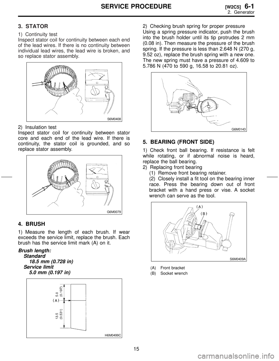
3. STATOR
1) Continuity test
Inspect stator coil for continuity between each end
of the lead wires. If there is no continuity between
individual lead wires, the lead wire is broken, and
so replace stator assembly.
S6M0408
2) Insulation test
Inspect stator coil for continuity between stator
core and each end of the lead wire. If there is
continuity, the stator coil is grounded, and so
replace stator assembly.
G6M0079
4. BRUSH
1) Measure the length of each brush. If wear
exceeds the service limit, replace the brush. Each
brush has the service limit mark (A) on it.
Brush length:
Standard
18.5 mm (0.728 in)
Service limit
5.0 mm (0.197 in)
H6M0499C
2) Checking brush spring for proper pressure
Using a spring pressure indicator, push the brush
into the brush holder until its tip protrudes 2 mm
(0.08 in). Then measure the pressure of the brush
spring. If the pressure is less than 2.648 N (270 g,
9.52 oz), replace the brush spring with a new one.
The new spring must have a pressure of 4.609 to
5.786 N (470 to 590 g, 16.58 to 20.81 oz).
G6M0143
5. BEARING (FRONT SIDE)
1) Check front ball bearing. If resistance is felt
while rotating, or if abnormal noise is heard,
replace the ball bearing.
2) Replacing front bearing
(1) Remove front bearing retainer.
(2) Closely install a fit tool on the bearing inner
race. Press the bearing down out of front
bracket with a hand press or vise. A socket
wrench can serve as the tool.
S6M0409A
(A) Front bracket
(B) Socket wrench
15
[W2C5]6-1SERVICE PROCEDURE
2. Generator
Page 305 of 345
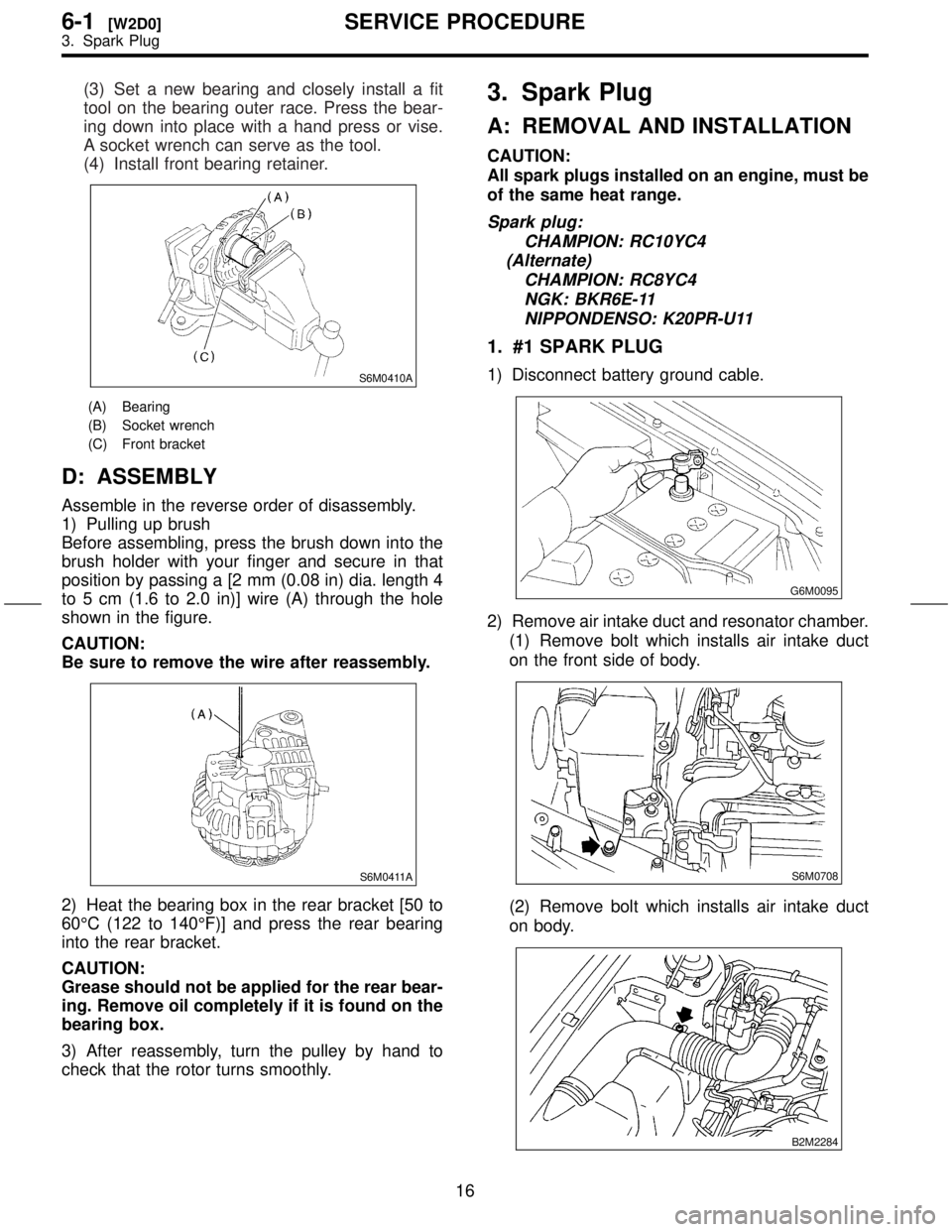
(3) Set a new bearing and closely install a fit
tool on the bearing outer race. Press the bear-
ing down into place with a hand press or vise.
A socket wrench can serve as the tool.
(4) Install front bearing retainer.
S6M0410A
(A) Bearing
(B) Socket wrench
(C) Front bracket
D: ASSEMBLY
Assemble in the reverse order of disassembly.
1) Pulling up brush
Before assembling, press the brush down into the
brush holder with your finger and secure in that
position by passing a [2 mm (0.08 in) dia. length 4
to 5 cm (1.6 to 2.0 in)] wire (A) through the hole
shown in the figure.
CAUTION:
Be sure to remove the wire after reassembly.
S6M0411A
2) Heat the bearing box in the rear bracket [50 to
60ÉC (122 to 140ÉF)] and press the rear bearing
into the rear bracket.
CAUTION:
Grease should not be applied for the rear bear-
ing. Remove oil completely if it is found on the
bearing box.
3) After reassembly, turn the pulley by hand to
check that the rotor turns smoothly.
3. Spark Plug
A: REMOVAL AND INSTALLATION
CAUTION:
All spark plugs installed on an engine, must be
of the same heat range.
Spark plug:
CHAMPION: RC10YC4
(Alternate)
CHAMPION: RC8YC4
NGK: BKR6E-11
NIPPONDENSO: K20PR-U11
1. #1 SPARK PLUG
1) Disconnect battery ground cable.
G6M0095
2) Remove air intake duct and resonator chamber.
(1) Remove bolt which installs air intake duct
on the front side of body.
S6M0708
(2) Remove bolt which installs air intake duct
on body.
B2M2284
16
6-1[W2D0]SERVICE PROCEDURE
3. Spark Plug
Page 306 of 345
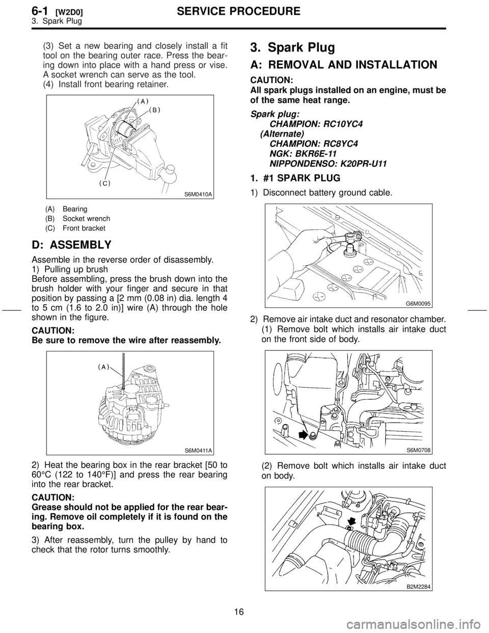
(3) Set a new bearing and closely install a fit
tool on the bearing outer race. Press the bear-
ing down into place with a hand press or vise.
A socket wrench can serve as the tool.
(4) Install front bearing retainer.
S6M0410A
(A) Bearing
(B) Socket wrench
(C) Front bracket
D: ASSEMBLY
Assemble in the reverse order of disassembly.
1) Pulling up brush
Before assembling, press the brush down into the
brush holder with your finger and secure in that
position by passing a [2 mm (0.08 in) dia. length 4
to 5 cm (1.6 to 2.0 in)] wire (A) through the hole
shown in the figure.
CAUTION:
Be sure to remove the wire after reassembly.
S6M0411A
2) Heat the bearing box in the rear bracket [50 to
60ÉC (122 to 140ÉF)] and press the rear bearing
into the rear bracket.
CAUTION:
Grease should not be applied for the rear bear-
ing. Remove oil completely if it is found on the
bearing box.
3) After reassembly, turn the pulley by hand to
check that the rotor turns smoothly.
3. Spark Plug
A: REMOVAL AND INSTALLATION
CAUTION:
All spark plugs installed on an engine, must be
of the same heat range.
Spark plug:
CHAMPION: RC10YC4
(Alternate)
CHAMPION: RC8YC4
NGK: BKR6E-11
NIPPONDENSO: K20PR-U11
1. #1 SPARK PLUG
1) Disconnect battery ground cable.
G6M0095
2) Remove air intake duct and resonator chamber.
(1) Remove bolt which installs air intake duct
on the front side of body.
S6M0708
(2) Remove bolt which installs air intake duct
on body.
B2M2284
16
6-1[W2D0]SERVICE PROCEDURE
3. Spark Plug
Page 310 of 345
7) Install in the reverse order of removal.
Tightening torque (Spark plug):
20.6
±2.9 N´m (2.10±0.30 kg-m, 15.19±2.14
ft-lb)
CAUTION:
The above torque should be only applied to
new spark plugs without oil on their threads.
In case their threads are lubricated, the torque
should be reduced by approximately 1/3 of the
specified torque in order to avoid over-stress-
ing.
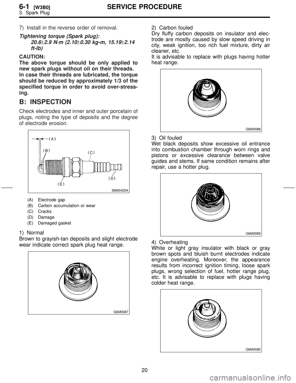
B: INSPECTION
Check electrodes and inner and outer porcelain of
plugs, noting the type of deposits and the degree
of electrode erosion.
S6M0420A
(A) Electrode gap
(B) Carbon accumulation or wear
(C) Cracks
(D) Damage
(E) Damaged gasket
1) Normal
Brown to grayish-tan deposits and slight electrode
wear indicate correct spark plug heat range.
G6M0087
2) Carbon fouled
Dry fluffy carbon deposits on insulator and elec-
trode are mostly caused by slow speed driving in
city, weak ignition, too rich fuel mixture, dirty air
cleaner, etc.
It is advisable to replace with plugs having hotter
heat range.
G6M0088
3) Oil fouled
Wet black deposits show excessive oil entrance
into combustion chamber through worn rings and
pistons or excessive clearance between valve
guides and stems. If same condition remains after
repair, use a hotter plug.
G6M0089
4) Overheating
White or light gray insulator with black or gray
brown spots and bluish burnt electrodes indicate
engine overheating. Moreover, the appearance
results from incorrect ignition timing, loose spark
plugs, wrong selection of fuel, hotter range plug,
etc. It is advisable to replace with plugs having
colder heat range.
G6M0090
20
6-1[W3B0]SERVICE PROCEDURE
3. Spark Plug