Page 159 of 345
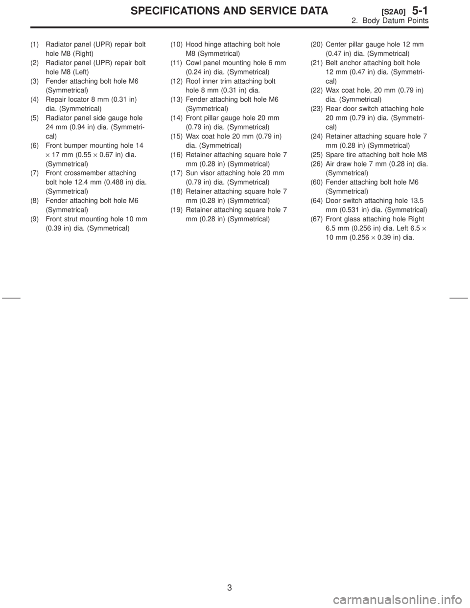
(1) Radiator panel (UPR) repair bolt
hole M8 (Right)
(2) Radiator panel (UPR) repair bolt
hole M8 (Left)
(3) Fender attaching bolt hole M6
(Symmetrical)
(4) Repair locator 8 mm (0.31 in)
dia. (Symmetrical)
(5) Radiator panel side gauge hole
24 mm (0.94 in) dia. (Symmetri-
cal)
(6) Front bumper mounting hole 14
´17 mm (0.55´0.67 in) dia.
(Symmetrical)
(7) Front crossmember attaching
bolt hole 12.4 mm (0.488 in) dia.
(Symmetrical)
(8) Fender attaching bolt hole M6
(Symmetrical)
(9) Front strut mounting hole 10 mm
(0.39 in) dia. (Symmetrical)(10) Hood hinge attaching bolt hole
M8 (Symmetrical)
(11) Cowl panel mounting hole 6 mm
(0.24 in) dia. (Symmetrical)
(12) Roof inner trim attaching bolt
hole 8 mm (0.31 in) dia.
(13) Fender attaching bolt hole M6
(Symmetrical)
(14) Front pillar gauge hole 20 mm
(0.79 in) dia. (Symmetrical)
(15) Wax coat hole 20 mm (0.79 in)
dia. (Symmetrical)
(16) Retainer attaching square hole 7
mm (0.28 in) (Symmetrical)
(17) Sun visor attaching hole 20 mm
(0.79 in) dia. (Symmetrical)
(18) Retainer attaching square hole 7
mm (0.28 in) (Symmetrical)
(19) Retainer attaching square hole 7
mm (0.28 in) (Symmetrical)(20) Center pillar gauge hole 12 mm
(0.47 in) dia. (Symmetrical)
(21) Belt anchor attaching bolt hole
12 mm (0.47 in) dia. (Symmetri-
cal)
(22) Wax coat hole, 20 mm (0.79 in)
dia. (Symmetrical)
(23) Rear door switch attaching hole
20 mm (0.79 in) dia. (Symmetri-
cal)
(24) Retainer attaching square hole 7
mm (0.28 in) (Symmetrical)
(25) Spare tire attaching bolt hole M8
(26) Air draw hole 7 mm (0.28 in) dia.
(Symmetrical)
(60) Fender attaching bolt hole M6
(Symmetrical)
(64) Door switch attaching hole 13.5
mm (0.531 in) dia. (Symmetrical)
(67) Front glass attaching hole Right
6.5 mm (0.256 in) dia. Left 6.5´
10 mm (0.256´0.39 in) dia.
3
[S2A0]5-1SPECIFICATIONS AND SERVICE DATA
2. Body Datum Points
Page 160 of 345
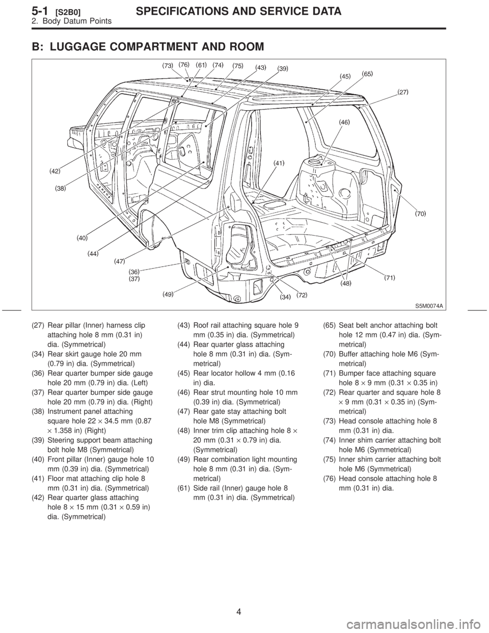
B: LUGGAGE COMPARTMENT AND ROOM
S5M0074A
(27) Rear pillar (Inner) harness clip
attaching hole 8 mm (0.31 in)
dia. (Symmetrical)
(34) Rear skirt gauge hole 20 mm
(0.79 in) dia. (Symmetrical)
(36) Rear quarter bumper side gauge
hole 20 mm (0.79 in) dia. (Left)
(37) Rear quarter bumper side gauge
hole 20 mm (0.79 in) dia. (Right)
(38) Instrument panel attaching
square hole 22´34.5 mm (0.87
´1.358 in) (Right)
(39) Steering support beam attaching
bolt hole M8 (Symmetrical)
(40) Front pillar (Inner) gauge hole 10
mm (0.39 in) dia. (Symmetrical)
(41) Floor mat attaching clip hole 8
mm (0.31 in) dia. (Symmetrical)
(42) Rear quarter glass attaching
hole 8´15 mm (0.31´0.59 in)
dia. (Symmetrical)(43) Roof rail attaching square hole 9
mm (0.35 in) dia. (Symmetrical)
(44) Rear quarter glass attaching
hole 8 mm (0.31 in) dia. (Sym-
metrical)
(45) Rear locator hollow 4 mm (0.16
in) dia.
(46) Rear strut mounting hole 10 mm
(0.39 in) dia. (Symmetrical)
(47) Rear gate stay attaching bolt
hole M8 (Symmetrical)
(48) Inner trim clip attaching hole 8´
20 mm (0.31´0.79 in) dia.
(Symmetrical)
(49) Rear combination light mounting
hole 8 mm (0.31 in) dia. (Sym-
metrical)
(61) Side rail (Inner) gauge hole 8
mm (0.31 in) dia. (Symmetrical)(65) Seat belt anchor attaching bolt
hole 12 mm (0.47 in) dia. (Sym-
metrical)
(70) Buffer attaching hole M6 (Sym-
metrical)
(71) Bumper face attaching square
hole 8´9 mm (0.31´0.35 in)
(72) Rear quarter and square hole 8
´9 mm (0.31´0.35 in) (Sym-
metrical)
(73) Head console attaching hole 8
mm (0.31 in) dia.
(74) Inner shim carrier attaching bolt
hole M6 (Symmetrical)
(75) Inner shim carrier attaching bolt
hole M6 (Symmetrical)
(76) Head console attaching hole 8
mm (0.31 in) dia.
4
5-1[S2B0]SPECIFICATIONS AND SERVICE DATA
2. Body Datum Points
Page 183 of 345
6. Sunroof
S5M0290A
(1) Glass lid
(2) Rear drain ASSY
(3) Frame ASSY
(4) Motor ASSY
(5) Drive unit
(6) Drain tube(7) Harness
(8) Sunshade
(9) Garnish
(10) Frame bracket
(11) Cover
(12) Deflector(13) Shim
Tightening torque: N´m (kg-m, ft-lb)
T:
7.4±2.0 (0.75±0.2, 5.4±1.4)
27
[C600]5-1COMPONENT PARTS
6. Sunroof
Page 204 of 345
15. Sunroof
A: REMOVAL AND INSTALLATION
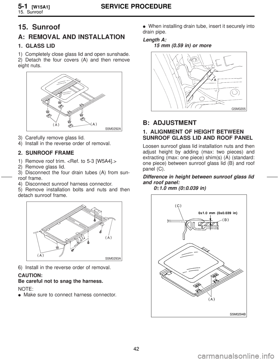
1. GLASS LID
1) Completely close glass lid and open sunshade.
2) Detach the four covers (A) and then remove
eight nuts.
S5M0292A
3) Carefully remove glass lid.
4) Install in the reverse order of removal.
2. SUNROOF FRAME
1) Remove roof trim.
2) Remove glass lid.
3) Disconnect the four drain tubes (A) from sun-
roof frame.
4) Disconnect sunroof harness connector.
5) Remove installation bolts and nuts and then
detach sunroof frame.
S5M0293A
6) Install in the reverse order of removal.
CAUTION:
Be careful not to snag the harness.
NOTE:
IMake sure to connect harness connector.IWhen installing drain tube, insert it securely into
drain pipe.
Length A:
15 mm (0.59 in) or more
G5M0205
B: ADJUSTMENT
1. ALIGNMENT OF HEIGHT BETWEEN
SUNROOF GLASS LID AND ROOF PANEL
Loosen sunroof glass lid installation nuts and then
adjust height by adding (max: two pieces) and
extracting (max: one piece) shim(s) (A) (standard:
one piece) between sunroof glass lid (B) and roof
panel (C).
Difference in height between sunroof glass lid
and roof panel:
0
±1.0 mm (0±0.039 in)
S5M0294B
42
5-1[W15A1]SERVICE PROCEDURE
15. Sunroof
Page 205 of 345
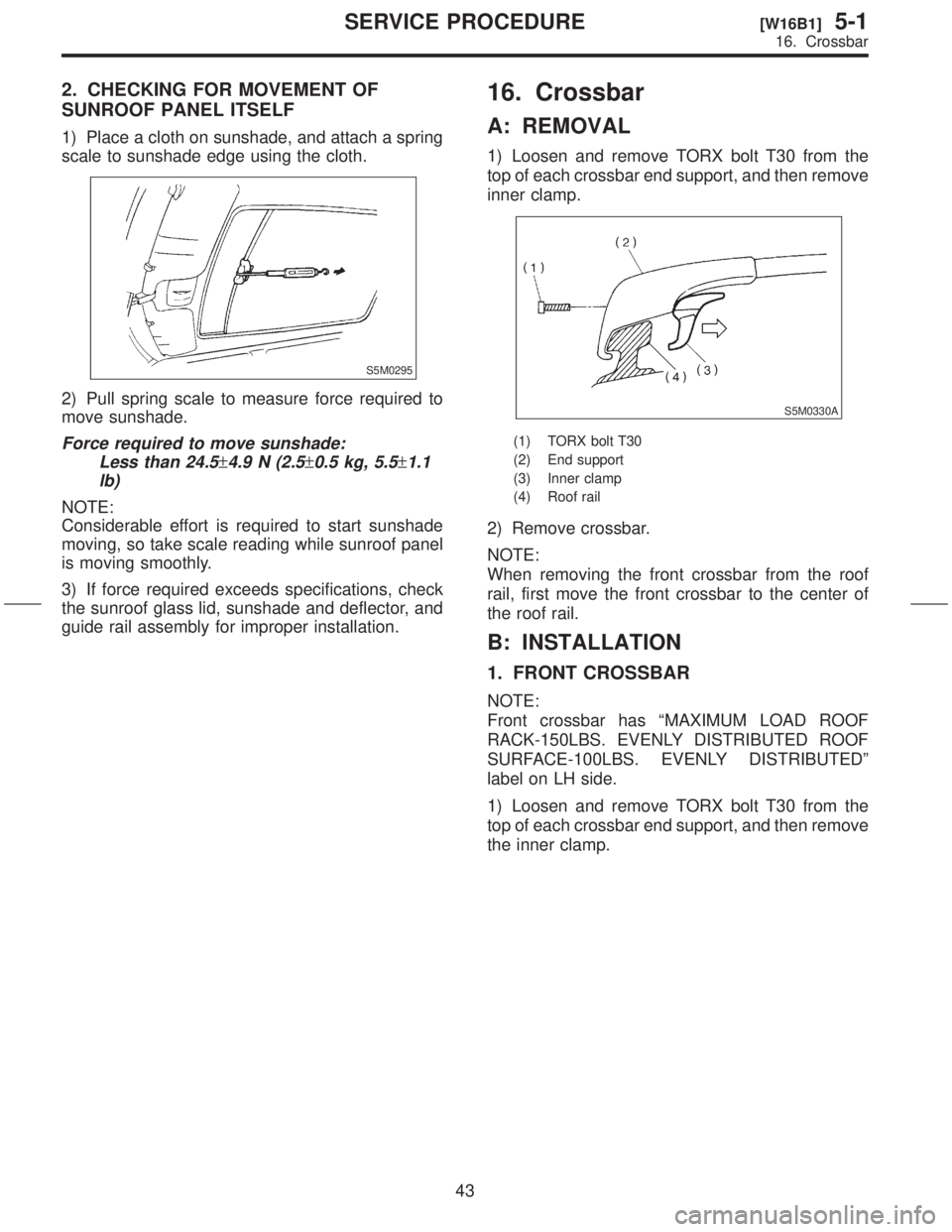
2. CHECKING FOR MOVEMENT OF
SUNROOF PANEL ITSELF
1) Place a cloth on sunshade, and attach a spring
scale to sunshade edge using the cloth.
S5M0295
2) Pull spring scale to measure force required to
move sunshade.
Force required to move sunshade:
Less than 24.5
±4.9 N (2.5±0.5 kg, 5.5±1.1
lb)
NOTE:
Considerable effort is required to start sunshade
moving, so take scale reading while sunroof panel
is moving smoothly.
3) If force required exceeds specifications, check
the sunroof glass lid, sunshade and deflector, and
guide rail assembly for improper installation.
16. Crossbar
A: REMOVAL
1) Loosen and remove TORX bolt T30 from the
top of each crossbar end support, and then remove
inner clamp.
S5M0330A
(1) TORX bolt T30
(2) End support
(3) Inner clamp
(4) Roof rail
2) Remove crossbar.
NOTE:
When removing the front crossbar from the roof
rail, first move the front crossbar to the center of
the roof rail.
B: INSTALLATION
1. FRONT CROSSBAR
NOTE:
Front crossbar has ªMAXIMUM LOAD ROOF
RACK-150LBS. EVENLY DISTRIBUTED ROOF
SURFACE-100LBS. EVENLY DISTRIBUTEDº
label on LH side.
1) Loosen and remove TORX bolt T30 from the
top of each crossbar end support, and then remove
the inner clamp.
43
[W16B1]5-1SERVICE PROCEDURE
16. Crossbar
Page 206 of 345
2.
SUNROOF
1\)
scale
S5M0295
2\)
move
ForceLess
\2614.9\2610.5\2611.1
lb\)
NOTE:
Considerable
moving,
is
3\)
the
guide
16.
A:
1\)
top
inner
S5M0330A
\(1\)
\(2\)
\(3\)
\(4\)
2\)
NOTE:
When
rail,
the
B:
1.
NOTE:
Front
RACK-150LBS.
SURF
label
1\)
top
the
43
[W16B1]5-1SER
16.
Page 208 of 345
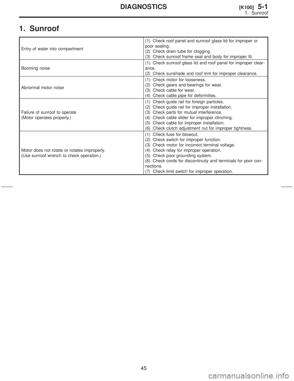
1. Sunroof
Entry of water into compartment(1) Check roof panel and sunroof glass lid for improper or
poor sealing.
(2) Check drain tube for clogging.
(3) Check sunroof frame seal and body for improper fit.
Booming noise(1) Check sunroof glass lid and roof panel for improper clear-
ance.
(2) Check sunshade and roof trim for improper clearance.
Abnormal motor noise(1) Check motor for looseness.
(2) Check gears and bearings for wear.
(3) Check cable for wear.
(4) Check cable pipe for deformities.
Failure of sunroof to operate
(Motor operates properly.)(1) Check guide rail for foreign particles.
(2) Check guide rail for improper installation.
(3) Check parts for mutual interference.
(4) Check cable slider for improper clinching.
(5) Check cable for improper installation.
(6) Check clutch adjustment nut for improper tightness.
Motor does not rotate or rotates improperly.
(Use sunroof wrench to check operation.)(1) Check fuse for blowout.
(2) Check switch for improper function.
(3) Check motor for incorrect terminal voltage.
(4) Check relay for improper operation.
(5) Check poor grounding system.
(6) Check cords for discontinuity and terminals for poor con-
nections.
(7) Check limit switch for improper operation.
45
[K100]5-1DIAGNOSTICS
1. Sunroof
Page 229 of 345
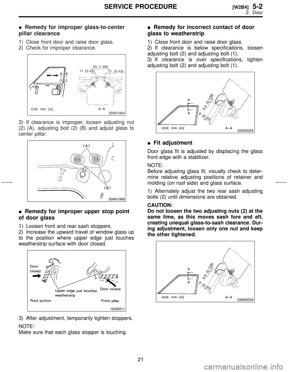
IRemedy for improper glass-to-center
pillar clearance
1) Close front door and raise door glass.
2) Check for improper clearance.
S5M0198A
3) If clearance is improper, loosen adjusting nut
(2) (A), adjusting bolt (2) (B) and adjust glass to
center pillar.
S5M0199B
IRemedy for improper upper stop point
of door glass
1) Loosen front and rear sash stoppers.
2) Increase the upward travel of window glass up
to the position where upper edge just touches
weatherstrip surface with door closed.
G5M0511
3) After adjustment, temporarily tighten stoppers.
NOTE:
Make sure that each glass stopper is touching.
IRemedy for incorrect contact of door
glass to weatherstrip
1) Close front door and raise door glass.
2) If clearance is below specifications, loosen
adjusting bolt (2) and adjusting bolt (1).
3) If clearance is over specifications, tighten
adjusting bolt (2) and adjusting bolt (1).
S5M0200A
IFit adjustment
Door glass fit is adjusted by displacing the glass
front edge with a stabilizer.
NOTE:
Before adjusting glass fit, visually check to deter-
mine relative adjusting positions of retainer and
molding (on roof side) and glass surface.
1) Alternately adjust the two rear sash adjusting
bolts (2) until dimensions are obtained.
CAUTION:
Do not loosen the two adjusting nuts (2) at the
same time, as this moves sash fore and aft,
creating unequal glass-to-sash clearance. Dur-
ing adjustment, loosen only one nut and keep
the other tightened.
S5M0200A
21
[W2B4]5-2SERVICE PROCEDURE
2. Door