Page 234 of 345
3. Rear Gate
A: REMOVAL AND INSTALLATION
CAUTION:
IBe careful not to scratch coated surfaces of
vehicle body and window glass during
removal. Place a cloth over the affected area.
IBe careful not to damage trim panels.
IUse an assistant when handling heavy parts.
IBe careful not to damage or lose small parts.
1. REAR GATE ASSEMBLY
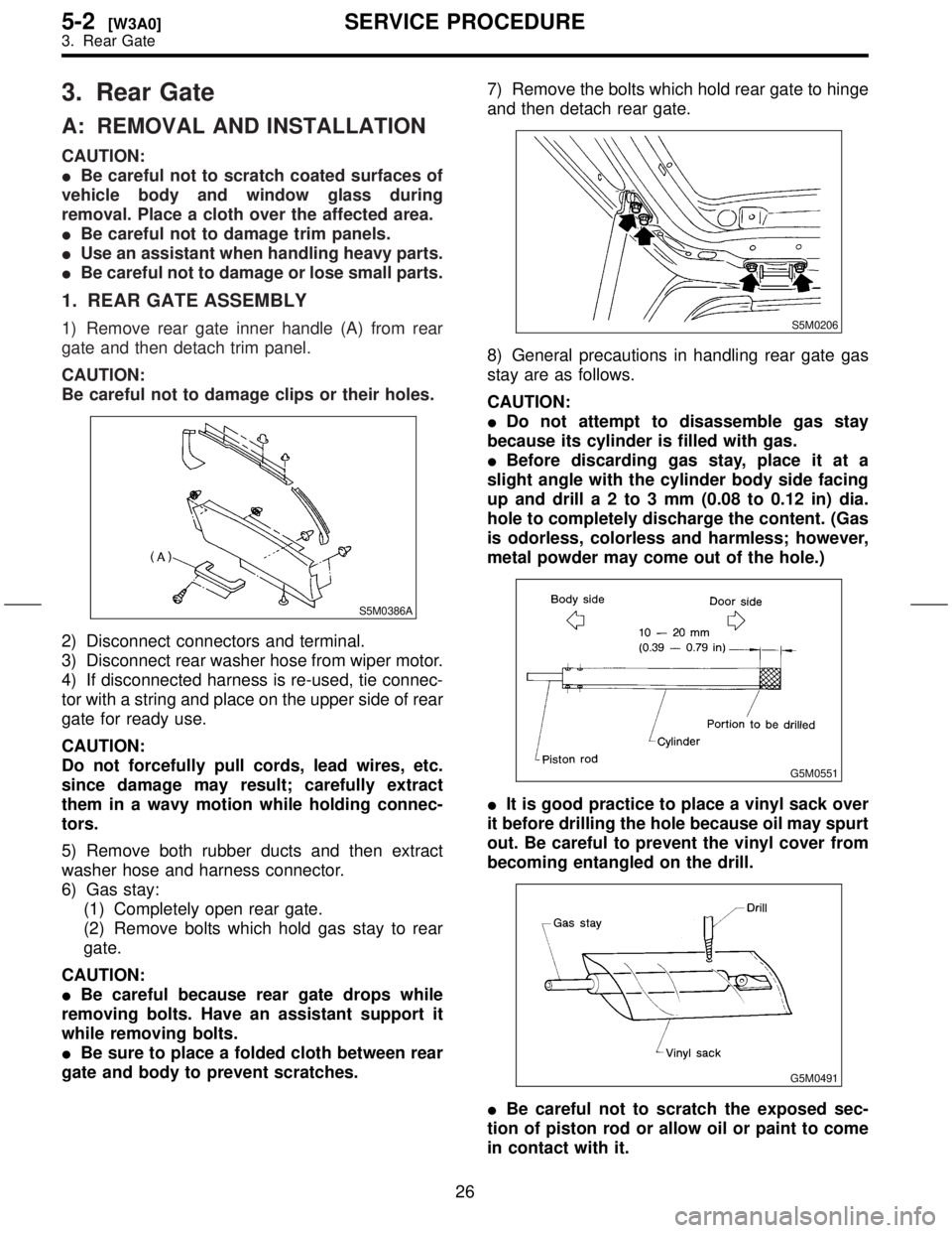
1) Remove rear gate inner handle (A) from rear
gate and then detach trim panel.
CAUTION:
Be careful not to damage clips or their holes.
S5M0386A
2) Disconnect connectors and terminal.
3) Disconnect rear washer hose from wiper motor.
4) If disconnected harness is re-used, tie connec-
tor with a string and place on the upper side of rear
gate for ready use.
CAUTION:
Do not forcefully pull cords, lead wires, etc.
since damage may result; carefully extract
them in a wavy motion while holding connec-
tors.
5) Remove both rubber ducts and then extract
washer hose and harness connector.
6) Gas stay:
(1) Completely open rear gate.
(2) Remove bolts which hold gas stay to rear
gate.
CAUTION:
IBe careful because rear gate drops while
removing bolts. Have an assistant support it
while removing bolts.
IBe sure to place a folded cloth between rear
gate and body to prevent scratches.7) Remove the bolts which hold rear gate to hinge
and then detach rear gate.
S5M0206
8) General precautions in handling rear gate gas
stay are as follows.
CAUTION:
IDo not attempt to disassemble gas stay
because its cylinder is filled with gas.
IBefore discarding gas stay, place it at a
slight angle with the cylinder body side facing
up and drilla2to3mm(0.08 to 0.12 in) dia.
hole to completely discharge the content. (Gas
is odorless, colorless and harmless; however,
metal powder may come out of the hole.)
G5M0551
IIt is good practice to place a vinyl sack over
it before drilling the hole because oil may spurt
out. Be careful to prevent the vinyl cover from
becoming entangled on the drill.
G5M0491
IBe careful not to scratch the exposed sec-
tion of piston rod or allow oil or paint to come
in contact with it.
26
5-2[W3A0]SERVICE PROCEDURE
3. Rear Gate
Page 240 of 345
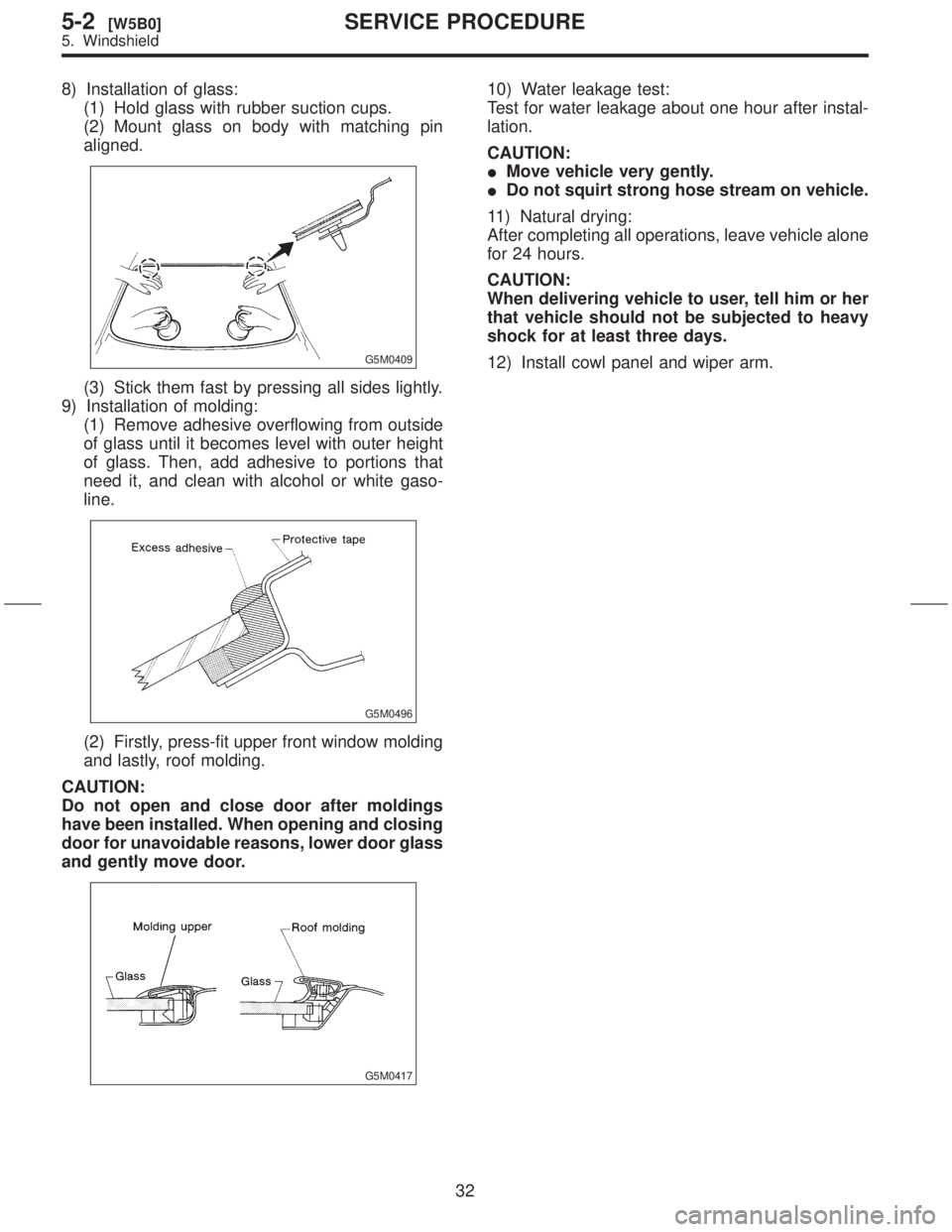
8) Installation of glass:
(1) Hold glass with rubber suction cups.
(2) Mount glass on body with matching pin
aligned.
G5M0409
(3) Stick them fast by pressing all sides lightly.
9) Installation of molding:
(1) Remove adhesive overflowing from outside
of glass until it becomes level with outer height
of glass. Then, add adhesive to portions that
need it, and clean with alcohol or white gaso-
line.
G5M0496
(2) Firstly, press-fit upper front window molding
and lastly, roof molding.
CAUTION:
Do not open and close door after moldings
have been installed. When opening and closing
door for unavoidable reasons, lower door glass
and gently move door.
G5M0417
10) Water leakage test:
Test for water leakage about one hour after instal-
lation.
CAUTION:
IMove vehicle very gently.
IDo not squirt strong hose stream on vehicle.
11) Natural drying:
After completing all operations, leave vehicle alone
for 24 hours.
CAUTION:
When delivering vehicle to user, tell him or her
that vehicle should not be subjected to heavy
shock for at least three days.
12) Install cowl panel and wiper arm.
32
5-2[W5B0]SERVICE PROCEDURE
5. Windshield
Page 243 of 345
5) Application of adhesive:
(1) Cut nozzle tip as shown in the figure.
G5M0414
(2) Open cartridge and put it into a gun with
nozzle attached.
(3) Apply adhesive uniformly to all sides of
adhesion surface while operating gun along
glass end face.
6) Installation of glass:
(1) Hold glass with rubber suction cups.
(2) Mount glass on body with matching pins (A)
aligned.
S5M0211B
(3) Attach quickly and press all sides lightly.7) Water leakage test:
After installing glass, test for water leakage after
about one hour.
CAUTION:
IMove vehicle slowly.
IWhen opening and closing door, lower door
glass and move door gently.
IDo not squirt strong hose stream on vehicle.
8) Natural drying:
After completing all operations, leave vehicle alone
for 24 hours.
CAUTION:
When delivering vehicle to user, tell him or her
that vehicle should not be subjected to heavy
shock for at least three days.
35
[W7B0]5-2SERVICE PROCEDURE
7. Rear Quarter Glass
Page 244 of 345
1. Door Glass
Condition Apparent cause/Correction
Glass in fully closed
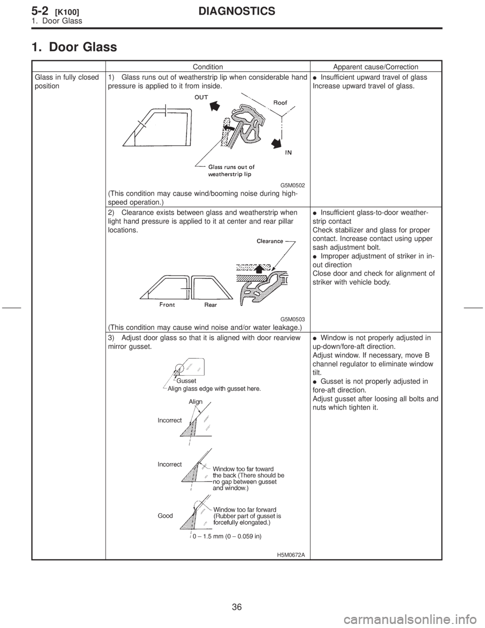
position1) Glass runs out of weatherstrip lip when considerable hand
pressure is applied to it from inside.
G5M0502
(This condition may cause wind/booming noise during high-
speed operation.)IInsufficient upward travel of glass
Increase upward travel of glass.
2) Clearance exists between glass and weatherstrip when
light hand pressure is applied to it at center and rear pillar
locations.
G5M0503
(This condition may cause wind noise and/or water leakage.)IInsufficient glass-to-door weather-
strip contact
Check stabilizer and glass for proper
contact. Increase contact using upper
sash adjustment bolt.
IImproper adjustment of striker in in-
out direction
Close door and check for alignment of
striker with vehicle body.
3) Adjust door glass so that it is aligned with door rearview
mirror gusset.
H5M0672A
IWindow is not properly adjusted in
up-down/fore-aft direction.
Adjust window. If necessary, move B
channel regulator to eliminate window
tilt.
IGusset is not properly adjusted in
fore-aft direction.
Adjust gusset after loosing all bolts and
nuts which tighten it.
36
5-2[K100]DIAGNOSTICS
1. Door Glass
Page 257 of 345
10) If any mechanism does not function properly,
loosen bolts (C) and (D), slide seat as required,
insert all lock plate pawls into holes in slide rail
brackets, and tighten bolts (C) and (D) in that
order.
11) Install bolt cover on rear end of slide rail.
12) Install headrest on backrest.
NOTE:
Tighten bolts in the designated order.2. Rear Seat
A: REMOVAL AND INSTALLATION
1. CUSHION
1) Remove bolts securing hinges (located at front
of cushion) to body.
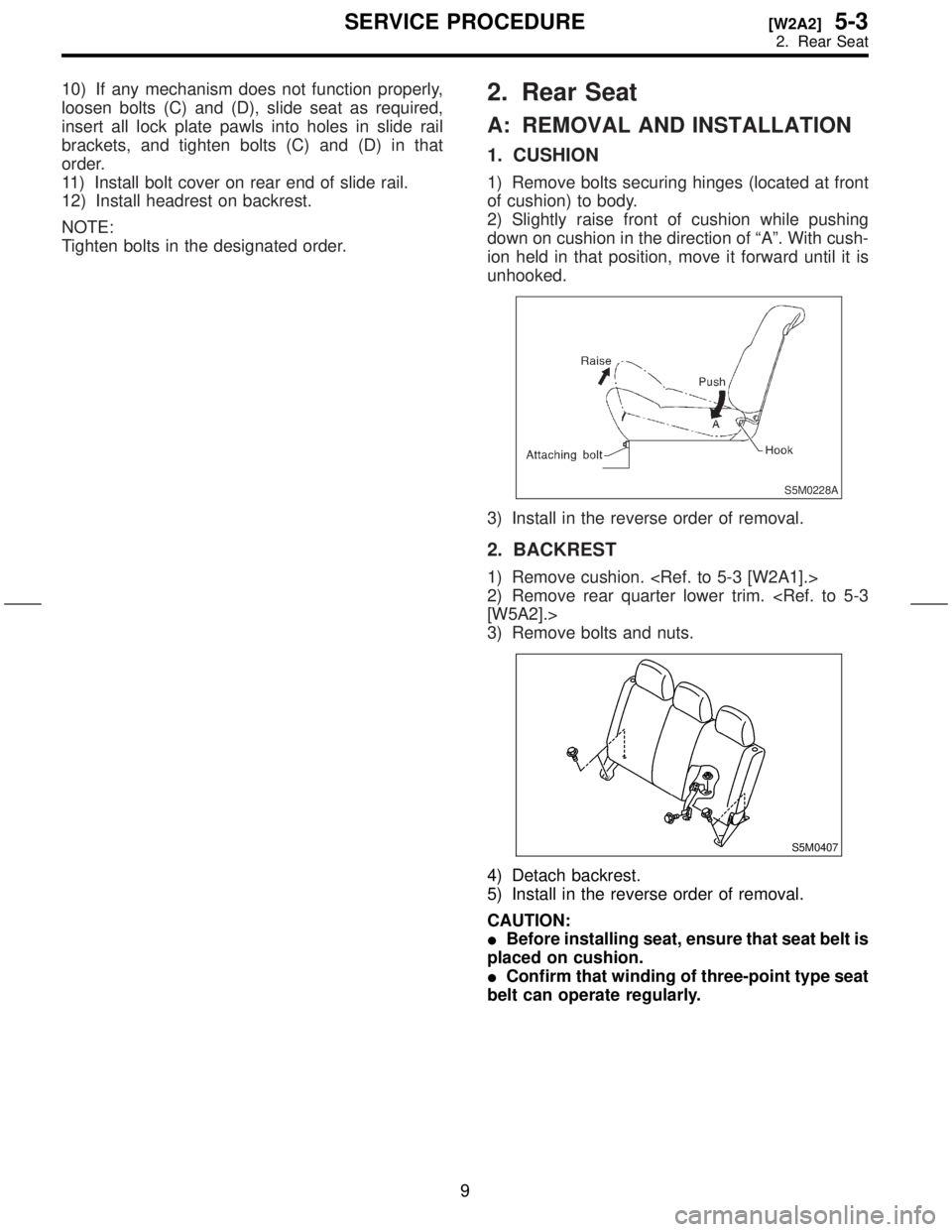
2) Slightly raise front of cushion while pushing
down on cushion in the direction of ªAº. With cush-
ion held in that position, move it forward until it is
unhooked.
S5M0228A
3) Install in the reverse order of removal.
2. BACKREST
1) Remove cushion.
2) Remove rear quarter lower trim.
[W5A2].>
3) Remove bolts and nuts.
S5M0407
4) Detach backrest.
5) Install in the reverse order of removal.
CAUTION:
IBefore installing seat, ensure that seat belt is
placed on cushion.
IConfirm that winding of three-point type seat
belt can operate regularly.
9
[W2A2]5-3SERVICE PROCEDURE
2. Rear Seat
Page 275 of 345
2. Inspection and Replacement
Standards
A: VEHICLES WHICH BECOME
INVOLVED IN A COLLISION
If the vehicle equipped with an SRS airbag system
is damaged in a collision, the airbag system parts
must be checked and replaced in accordance with
the following standards:
IAfter faulty parts are replaced, the warning light
operation must be checked.
IWhen the ignition switch is turned ON, it lights
up for about 7 seconds and then it goes out for at
least 30 seconds.
IThe trouble code stored in memory must be
erased after the check.
B: AIRBAG MODULE (DRIVER AND
PASSENGER)
1. INSPECTION STANDARD
IThe vehicle damaged in a collision (regardless
of whether or not airbag is deployed).
IThe designated trouble code is output during
self-diagnosis.
2. REPLACEMENT STANDARD
IAirbag is deployed.
IThe pad surface is scratched or cracked.
IHarness and/or connector is deformed or
cracked, their circuits are broken, lead wire is
exposed, etc.
IMounting bracket is cracked or deformed.
IThe module surface is fouled with foreign mat-
ter. (grease, oil, water, cleaning solvent, etc.)
IAirbag module dropped to the floor/ground.
IAirbag module determined as faulty during self-
diagnosis.
C: AIRBAG MODULE (SIDE)
1. INSPECTION STANDARD
IThe vehicle damaged in a side collision (regard-
less of whether or not airbag is deployed).
IThe designated trouble code is output during
self-diagnosis.
2. REPLACEMENT STANDARD
ISide airbag is deployed.
IThe front seat assembly is damaged or
deformed.
IHarness and/or connector is deformed or
cracked, their circuits are broken, lead wire is
exposed, etc.
IMounting bracket is cracked or deformed.ISide airbag module determined as faulty during
self-diagnosis.
D: MAIN HARNESS
1. INSPECTION STANDARD
IA vehicle damaged in a collision (regardless of
whether or not airbag is deployed).
IThe designated trouble code is output during
self-diagnosis.
2. REPLACEMENT STANDARD
IHarness circuit is broken, lead wire is exposed,
corrugated tube is cracked, etc.
IConnector is scratched or cracked.
IThe designated trouble code is output during
self-diagnosis.
E: AIRBAG CONTROL MODULE
1. INSPECTION STANDARD
IA vehicle damaged in a collision (regardless of
whether or not airbag is deployed).
IThe designated trouble code is output during
self-diagnosis.
2. REPLACEMENT STANDARD
IControl module is cracked or deformed.
IMounting bracket is cracked or deformed.
IConnector is scratched or cracked.
IControl module dropped to the floor/ground.
IControl module determined as faulty during
diagnostics.
IFront or side airbag is deployed.
F: ROLL CONNECTOR
1. INSPECTION STANDARD
IA vehicle damaged in a collision (regardless of
whether or not airbag is deployed).
IThe designated trouble code is output during
self-diagnosis.
2. REPLACEMENT STANDARD
ICombination switch or steering roll connector is
deformed or cracked.
5
[W2F2]5-5SERVICE PROCEDURE
2. Inspection and Replacement Standards
Page 278 of 345
3. Airbag Module
A: REMOVAL AND INSTALLATION
CAUTION:
IThe airbag module (driver, passenger and
side) must not be disassembled. The airbag
module cannot be used again once inflated.
G5M0299
IWhen removing and installing the airbag
module (driver, passenger and side), the opera-
tor should stand, as much as possible, on the
side of the airbag module.
G5M0300
IAfter removal, the airbag module (driver,
passenger and side) should be kept away from
heat and light sources, and stored on a clean,
flat surface to prevent from any damage to its
lower structure.
G5M0301
IDo not check airbag module (driver, passen-
ger and side) continuity with airbag removed
from the vehicle body.
G5M0302
IReplace airbag module (driver, passenger
and side) with a new one, should any of the
following conditions develop:
IPad surface is scratched or cracked.
IConnector harness is damaged.
IInflator side structure of module is
cracked or deformed.
IModule is excessively stained with water,
oil, etc.
IModule was accidentally dropped.
IThe front seat assembly is damaged or
deformed.
IThe removed front seat with the airbag mod-
ule must be kept on its back. At this time, keep
the module side at least 200 mm (7.87 in) away
from walls or other objects.
B5M0515A
8
5-5[W3A0]SERVICE PROCEDURE
3. Airbag Module
Page 282 of 345
5.
A:
1\)
2\)
for
3\)
roll
4\)
5\)
from
6\)
[W7A0].>
airbag
7\)
ness.
S5M0307
8\)
6.
A:
CAUTION:
IDo
ule.
G5M0322
I If
if
bag
G5M0323
I After
ule
light
G5M0324
1\)
2\)
for
3\)
4\)
[W1A0].>
5\)
ule.
12
5-5[W5A0]SER
5.
![SUBARU FORESTER 1999 Service Repair Manual 5.
A:
1\)
2\)
for
3\)
roll
4\)
5\)
from
6\)
[W7A0].>
airbag
7\)
ness.
S5M0307
8\)
6.
A:
CAUTION:
IDo
ule.
G5M0322
I If
if
bag
G5M0323
I After
ule
light
G5M0324
1\)
2\)
for
3\)
4\)
[W1A0].>
5\)
ule.
12](/manual-img/17/57427/w960_57427-281.png "SUBARU FORESTER 1999 Service Repair Manual 5.
A:
1\)
2\)
for
3\)
roll
4\)
5\)
from
6\)
[W7A0].>
airbag
7\)
ness.
S5M0307
8\)
6.
A:
CAUTION:
IDo
ule.
G5M0322
I If
if
bag
G5M0323
I After
ule
light
G5M0324
1\)
2\)
for
3\)
4\)
[W1A0].>
5\)
ule.
12")