Page 325 of 345
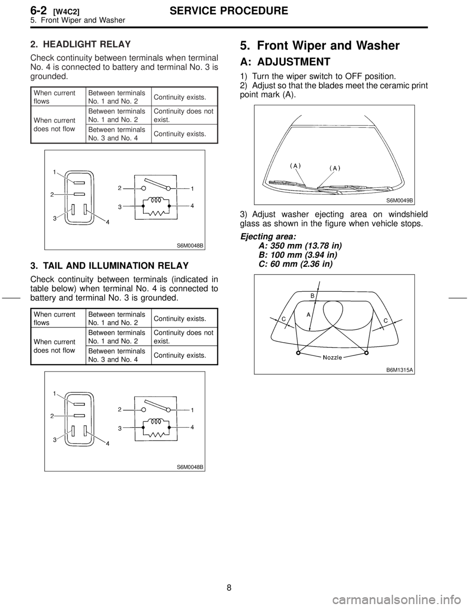
2. HEADLIGHT RELAY
Check continuity between terminals when terminal
No. 4 is connected to battery and terminal No. 3 is
grounded.
When current
flowsBetween terminals
No. 1 and No. 2Continuity exists.
When current
does not flowBetween terminals
No. 1 and No. 2Continuity does not
exist.
Between terminals
No. 3 and No. 4Continuity exists.
S6M0048B
3. TAIL AND ILLUMINATION RELAY
Check continuity between terminals (indicated in
table below) when terminal No. 4 is connected to
battery and terminal No. 3 is grounded.
When current
flowsBetween terminals
No. 1 and No. 2Continuity exists.
When current
does not flowBetween terminals
No. 1 and No. 2Continuity does not
exist.
Between terminals
No. 3 and No. 4Continuity exists.
S6M0048B
5. Front Wiper and Washer
A: ADJUSTMENT
1) Turn the wiper switch to OFF position.
2) Adjust so that the blades meet the ceramic print
point mark (A).
S6M0049B
3) Adjust washer ejecting area on windshield
glass as shown in the figure when vehicle stops.
Ejecting area:
A: 350 mm (13.78 in)
B: 100 mm (3.94 in)
C: 60 mm (2.36 in)
B6M1315A
8
6-2[W4C2]SERVICE PROCEDURE
5. Front Wiper and Washer
Page 326 of 345
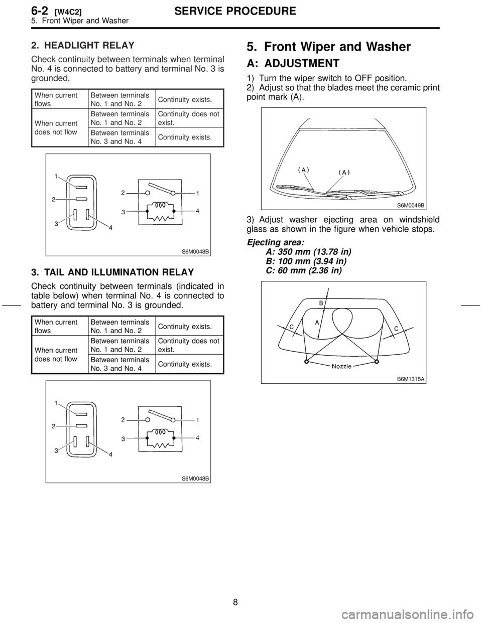
2. HEADLIGHT RELAY
Check continuity between terminals when terminal
No. 4 is connected to battery and terminal No. 3 is
grounded.
When current
flowsBetween terminals
No. 1 and No. 2Continuity exists.
When current
does not flowBetween terminals
No. 1 and No. 2Continuity does not
exist.
Between terminals
No. 3 and No. 4Continuity exists.
S6M0048B
3. TAIL AND ILLUMINATION RELAY
Check continuity between terminals (indicated in
table below) when terminal No. 4 is connected to
battery and terminal No. 3 is grounded.
When current
flowsBetween terminals
No. 1 and No. 2Continuity exists.
When current
does not flowBetween terminals
No. 1 and No. 2Continuity does not
exist.
Between terminals
No. 3 and No. 4Continuity exists.
S6M0048B
5. Front Wiper and Washer
A: ADJUSTMENT
1) Turn the wiper switch to OFF position.
2) Adjust so that the blades meet the ceramic print
point mark (A).
S6M0049B
3) Adjust washer ejecting area on windshield
glass as shown in the figure when vehicle stops.
Ejecting area:
A: 350 mm (13.78 in)
B: 100 mm (3.94 in)
C: 60 mm (2.36 in)
B6M1315A
8
6-2[W4C2]SERVICE PROCEDURE
5. Front Wiper and Washer
Page 342 of 345
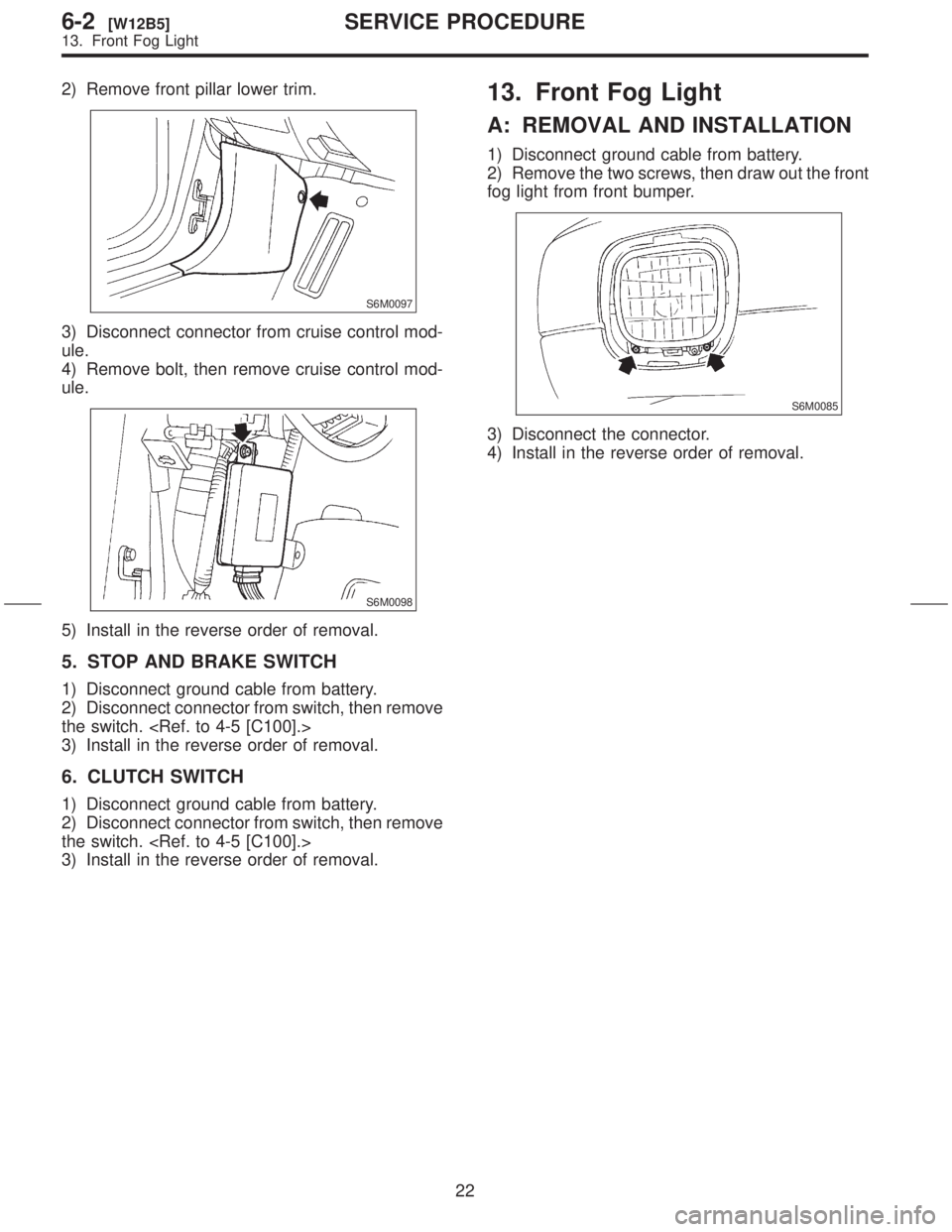
2) Remove front pillar lower trim.
S6M0097
3) Disconnect connector from cruise control mod-
ule.
4) Remove bolt, then remove cruise control mod-
ule.
S6M0098
5) Install in the reverse order of removal.
5. STOP AND BRAKE SWITCH
1) Disconnect ground cable from battery.
2) Disconnect connector from switch, then remove
the switch.
3) Install in the reverse order of removal.
6. CLUTCH SWITCH
1) Disconnect ground cable from battery.
2) Disconnect connector from switch, then remove
the switch.
3) Install in the reverse order of removal.
13. Front Fog Light
A: REMOVAL AND INSTALLATION
1) Disconnect ground cable from battery.
2) Remove the two screws, then draw out the front
fog light from front bumper.
S6M0085
3) Disconnect the connector.
4) Install in the reverse order of removal.
22
6-2[W12B5]SERVICE PROCEDURE
13. Front Fog Light