Page 177 of 345
4. Datum Points and Dimensions Concerning On-Board Aiming
Adjustment
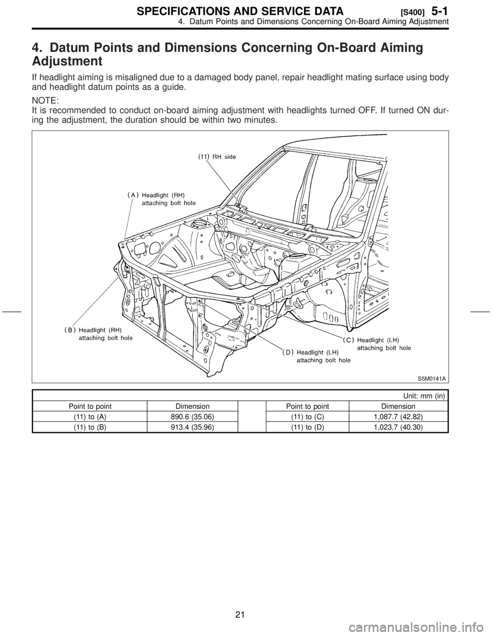
If headlight aiming is misaligned due to a damaged body panel, repair headlight mating surface using body
and headlight datum points as a guide.
NOTE:
It is recommended to conduct on-board aiming adjustment with headlights turned OFF. If turned ON dur-
ing the adjustment, the duration should be within two minutes.
S5M0141A
Unit: mm (in)
Point to point Dimension Point to point Dimension
(11) to (A) 890.6 (35.06) (11) to (C) 1,087.7 (42.82)
(11) to (B) 913.4 (35.96) (11) to (D) 1,023.7 (40.30)
21
[S400]5-1SPECIFICATIONS AND SERVICE DATA
4. Datum Points and Dimensions Concerning On-Board Aiming Adjustment
Page 187 of 345
2. Fuel Flap
A: REMOVAL AND INSTALLATION
1. FUEL FLAP
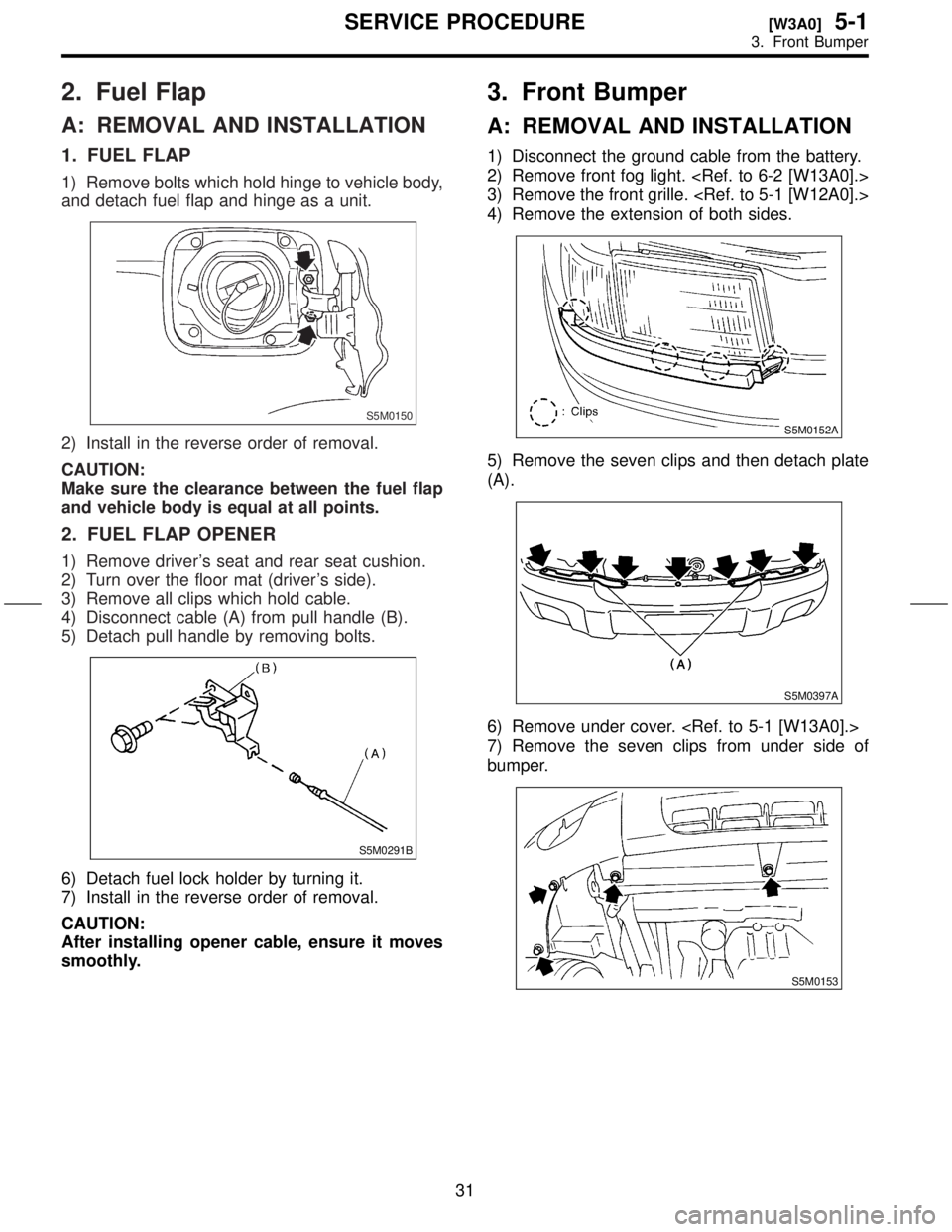
1) Remove bolts which hold hinge to vehicle body,
and detach fuel flap and hinge as a unit.
S5M0150
2) Install in the reverse order of removal.
CAUTION:
Make sure the clearance between the fuel flap
and vehicle body is equal at all points.
2. FUEL FLAP OPENER
1) Remove driver's seat and rear seat cushion.
2) Turn over the floor mat (driver's side).
3) Remove all clips which hold cable.
4) Disconnect cable (A) from pull handle (B).
5) Detach pull handle by removing bolts.
S5M0291B
6) Detach fuel lock holder by turning it.
7) Install in the reverse order of removal.
CAUTION:
After installing opener cable, ensure it moves
smoothly.
3. Front Bumper
A: REMOVAL AND INSTALLATION
1) Disconnect the ground cable from the battery.
2) Remove front fog light.
3) Remove the front grille.
4) Remove the extension of both sides.
S5M0152A
5) Remove the seven clips and then detach plate
(A).
S5M0397A
6) Remove under cover.
7) Remove the seven clips from under side of
bumper.
S5M0153
31
[W3A0]5-1SERVICE PROCEDURE
3. Front Bumper
Page 188 of 345
2. Fuel Flap
A: REMOVAL AND INSTALLATION
1. FUEL FLAP
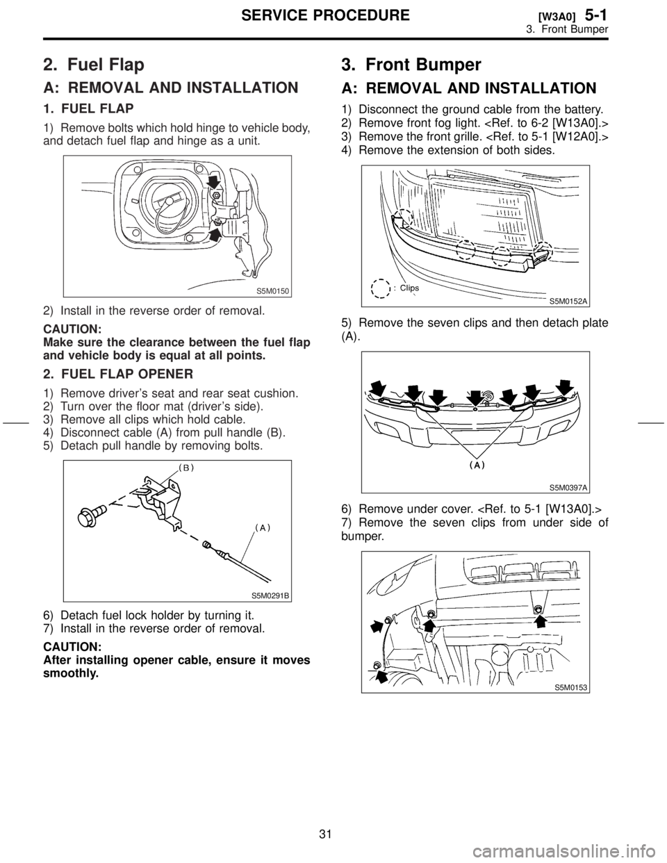
1) Remove bolts which hold hinge to vehicle body,
and detach fuel flap and hinge as a unit.
S5M0150
2) Install in the reverse order of removal.
CAUTION:
Make sure the clearance between the fuel flap
and vehicle body is equal at all points.
2. FUEL FLAP OPENER
1) Remove driver's seat and rear seat cushion.
2) Turn over the floor mat (driver's side).
3) Remove all clips which hold cable.
4) Disconnect cable (A) from pull handle (B).
5) Detach pull handle by removing bolts.
S5M0291B
6) Detach fuel lock holder by turning it.
7) Install in the reverse order of removal.
CAUTION:
After installing opener cable, ensure it moves
smoothly.
3. Front Bumper
A: REMOVAL AND INSTALLATION
1) Disconnect the ground cable from the battery.
2) Remove front fog light.
3) Remove the front grille.
4) Remove the extension of both sides.
S5M0152A
5) Remove the seven clips and then detach plate
(A).
S5M0397A
6) Remove under cover.
7) Remove the seven clips from under side of
bumper.
S5M0153
31
[W3A0]5-1SERVICE PROCEDURE
3. Front Bumper
Page 189 of 345
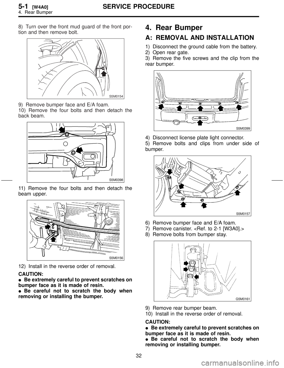
8) Turn over the front mud guard of the front por-
tion and then remove bolt.
S5M0154
9) Remove bumper face and E/A foam.
10) Remove the four bolts and then detach the
back beam.
S5M0398
11) Remove the four bolts and then detach the
beam upper.
S5M0156
12) Install in the reverse order of removal.
CAUTION:
IBe extremely careful to prevent scratches on
bumper face as it is made of resin.
IBe careful not to scratch the body when
removing or installing the bumper.
4. Rear Bumper
A: REMOVAL AND INSTALLATION
1) Disconnect the ground cable from the battery.
2) Open rear gate.
3) Remove the five screws and the clip from the
rear bumper.
S5M0399
4) Disconnect license plate light connector.
5) Remove bolts and clips from under side of
bumper.
S5M0157
6) Remove bumper face and E/A foam.
7) Remove canister.
8) Remove bolts from bumper stay.
G5M0161
9) Remove rear bumper beam.
10) Install in the reverse order of removal.
CAUTION:
IBe extremely careful to prevent scratches on
bumper face as it is made of resin.
IBe careful not to scratch the body when
removing or installing bumper.
32
5-1[W4A0]SERVICE PROCEDURE
4. Rear Bumper
Page 190 of 345
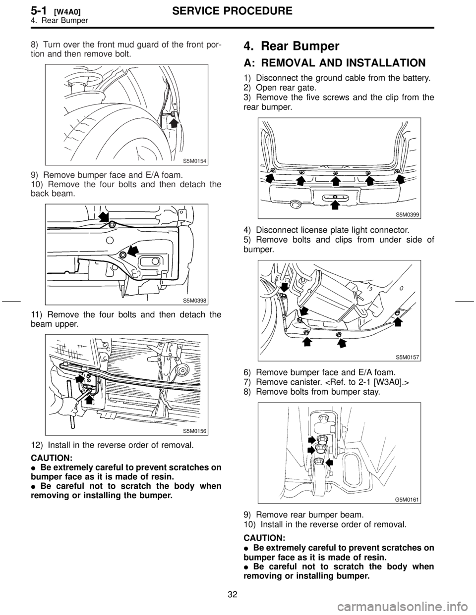
8) Turn over the front mud guard of the front por-
tion and then remove bolt.
S5M0154
9) Remove bumper face and E/A foam.
10) Remove the four bolts and then detach the
back beam.
S5M0398
11) Remove the four bolts and then detach the
beam upper.
S5M0156
12) Install in the reverse order of removal.
CAUTION:
IBe extremely careful to prevent scratches on
bumper face as it is made of resin.
IBe careful not to scratch the body when
removing or installing the bumper.
4. Rear Bumper
A: REMOVAL AND INSTALLATION
1) Disconnect the ground cable from the battery.
2) Open rear gate.
3) Remove the five screws and the clip from the
rear bumper.
S5M0399
4) Disconnect license plate light connector.
5) Remove bolts and clips from under side of
bumper.
S5M0157
6) Remove bumper face and E/A foam.
7) Remove canister.
8) Remove bolts from bumper stay.
G5M0161
9) Remove rear bumper beam.
10) Install in the reverse order of removal.
CAUTION:
IBe extremely careful to prevent scratches on
bumper face as it is made of resin.
IBe careful not to scratch the body when
removing or installing bumper.
32
5-1[W4A0]SERVICE PROCEDURE
4. Rear Bumper
Page 192 of 345
6. Repair Instructions for Colored PP Bumper
All PP bumpers are provided with a grained surface, and if the surface is damaged, it cannot normally be
restored to its former condition. Damage limited to shallow scratches that cause only a change in the lus-
tre of the base material or coating, can be almost fully restored. Before repairing a damaged area, explain
this point to the customer and obtain his or her understanding. Repair methods are outlined below, based
on a classification of the extent of damage.
A: MINOR DAMAGE CAUSING ONLY A CHANGE IN THE LUSTRE OF THE
BUMPER DUE TO A LIGHT TOUCH
Almost restorable.
Process
No.Process name Job contents
1 Cleaning Clean the area to be repaired using water.
2 Sanding Grind the repairing area with #500 sand paper in a ªfeatheringº motion.
3 FinishResin section Coated section
Repeatedly apply wax to the affected area
using a soft cloth (such as flannel). Recom-
mended wax: NITTO KASEI Soft 99 TIRE
WAX BLACK, or equivalent.Perform either the same operation as for the
resin section or process No. 18 and subse-
quent operations in the ª(3)º section, depend-
ing on the degree and nature of damage.
Polish the waxed area with a clean cloth after
5 to 10 minutes.
B: DEEP DAMAGE CAUSED BY SCRATCHING FENCES, ETC.
A dent cannot be repaired but a whitened or swelled part can be removed.
Process
No.Process name Job contents
1 Cleaning Clean damaged area with water.
2Removal of dam-
aged areaCut off protruding area, if any, due to collision, using a putty knife.
3 Sanding Grind the affected area with #100 to #500 sand paper.
4 FinishResin section Coated section
Same as Process No. 3 in the ª(1)º section.Perform Process No. 12 and subsequent
operations in the ª(3)º section.
34
5-1[W600]SERVICE PROCEDURE
6. Repair Instructions for Colored PP Bumper
Page 228 of 345
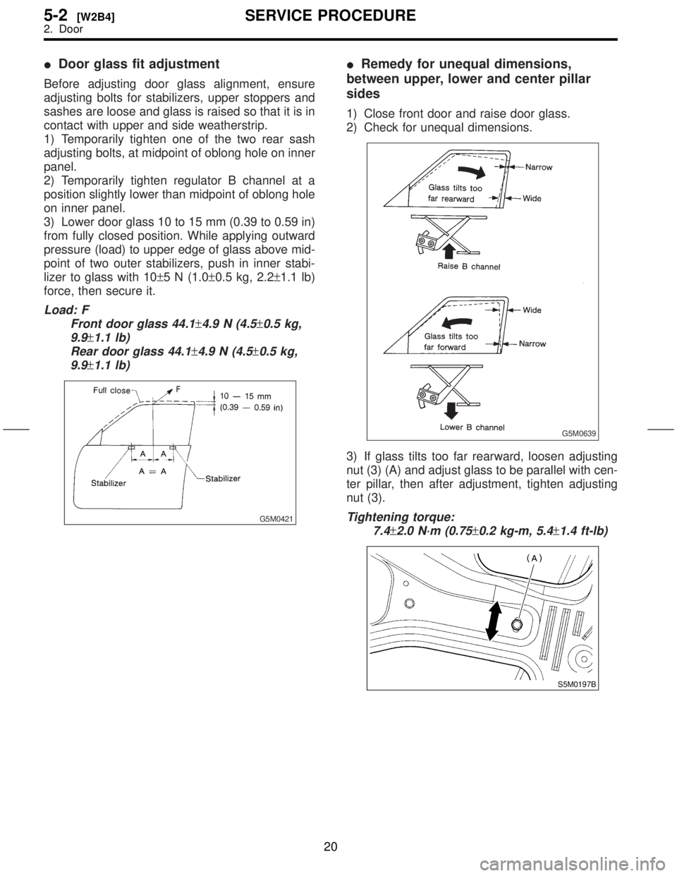
IDoor glass fit adjustment
Before adjusting door glass alignment, ensure
adjusting bolts for stabilizers, upper stoppers and
sashes are loose and glass is raised so that it is in
contact with upper and side weatherstrip.
1) Temporarily tighten one of the two rear sash
adjusting bolts, at midpoint of oblong hole on inner
panel.
2) Temporarily tighten regulator B channel at a
position slightly lower than midpoint of oblong hole
on inner panel.
3) Lower door glass 10 to 15 mm (0.39 to 0.59 in)
from fully closed position. While applying outward
pressure (load) to upper edge of glass above mid-
point of two outer stabilizers, push in inner stabi-
lizer to glass with 10±5 N (1.0±0.5 kg, 2.2±1.1 lb)
force, then secure it.
Load: F
Front door glass 44.1
±4.9 N (4.5±0.5 kg,
9.9
±1.1 lb)
Rear door glass 44.1
±4.9 N (4.5±0.5 kg,
9.9
±1.1 lb)
G5M0421
IRemedy for unequal dimensions,
between upper, lower and center pillar
sides
1) Close front door and raise door glass.
2) Check for unequal dimensions.
G5M0639
3) If glass tilts too far rearward, loosen adjusting
nut (3) (A) and adjust glass to be parallel with cen-
ter pillar, then after adjustment, tighten adjusting
nut (3).
Tightening torque:
7.4
±2.0 N´m (0.75±0.2 kg-m, 5.4±1.4 ft-lb)
S5M0197B
20
5-2[W2B4]SERVICE PROCEDURE
2. Door
Page 231 of 345
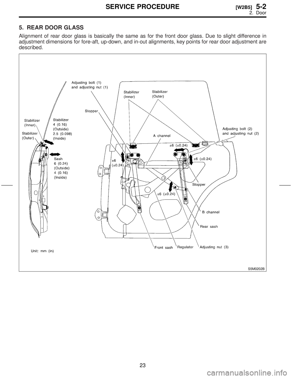
5. REAR DOOR GLASS
Alignment of rear door glass is basically the same as for the front door glass. Due to slight difference in
adjustment dimensions for fore-aft, up-down, and in-out alignments, key points for rear door adjustment are
described.
S5M0202B
23
[W2B5]5-2SERVICE PROCEDURE
2. Door