Page 89 of 345
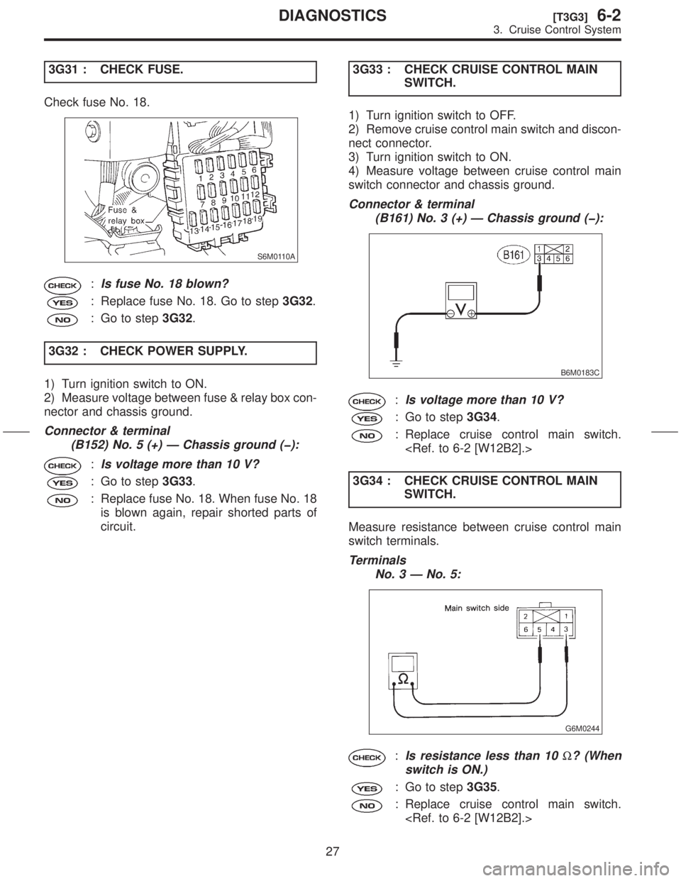
3G31 : CHECK FUSE.
Check fuse No. 18.
S6M0110A
:Is fuse No. 18 blown?
: Replace fuse No. 18. Go to step3G32.
: Go to step3G32.
3G32 : CHECK POWER SUPPLY.
1) Turn ignition switch to ON.
2) Measure voltage between fuse & relay box con-
nector and chassis ground.
Connector & terminal
(B152) No. 5 (+) Ð Chassis ground (þ):
:Is voltage more than 10 V?
: Go to step3G33.
: Replace fuse No. 18. When fuse No. 18
is blown again, repair shorted parts of
circuit.3G33 : CHECK CRUISE CONTROL MAIN
SWITCH.
1) Turn ignition switch to OFF.
2) Remove cruise control main switch and discon-
nect connector.
3) Turn ignition switch to ON.
4) Measure voltage between cruise control main
switch connector and chassis ground.
Connector & terminal
(B161) No. 3 (+) Ð Chassis ground (þ):
B6M0183C
:Is voltage more than 10 V?
: Go to step3G34.
: Replace cruise control main switch.
3G34 : CHECK CRUISE CONTROL MAIN
SWITCH.
Measure resistance between cruise control main
switch terminals.
Terminals
No. 3 Ð No. 5:
G6M0244
:Is resistance less than 10W? (When
switch is ON.)
: Go to step3G35.
: Replace cruise control main switch.
27
[T3G3]6-2DIAGNOSTICS
3. Cruise Control System
Page 90 of 345
3G35 : CHECK CRUISE CONTROL MAIN
SWITCH.
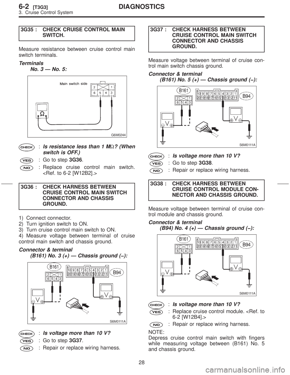
Measure resistance between cruise control main
switch terminals.
Terminals
No. 3 Ð No. 5:
G6M0244
:Is resistance less than 1 MW? (When
switch is OFF.)
: Go to step3G36.
: Replace cruise control main switch.
3G36 : CHECK HARNESS BETWEEN
CRUISE CONTROL MAIN SWITCH
CONNECTOR AND CHASSIS
GROUND.
1) Connect connector.
2) Turn ignition switch to ON.
3) Turn cruise control main switch to ON.
4) Measure voltage between terminal of cruise
control main switch and chassis ground.
Connector & terminal
(B161) No. 3 (+) Ð Chassis ground (þ):
S6M0111A
:Is voltage more than 10 V?
: Go to step3G37.
: Repair or replace wiring harness.3G37 : CHECK HARNESS BETWEEN
CRUISE CONTROL MAIN SWITCH
CONNECTOR AND CHASSIS
GROUND.
Measure voltage between terminal of cruise con-
trol main switch chassis ground.
Connector & terminal
(B161) No. 5 (+) Ð Chassis ground (þ):
S6M0111A
:Is voltage more than 10 V?
: Go to step3G38.
: Repair or replace wiring harness.
3G38 : CHECK HARNESS BETWEEN
CRUISE CONTROL MODULE CON-
NECTOR AND CHASSIS GROUND.
Measure voltage between terminal of cruise con-
trol module and chassis ground.
Connector & terminal
(B94) No. 4 (+) Ð Chassis ground (þ):
S6M0111A
:Is voltage more than 10 V?
: Replace cruise control module.
6-2 [W12B4].>
: Repair or replace wiring harness.
NOTE:
Depress cruise control main switch with fingers
while measuring voltage between (B161) No. 5
and chassis ground.
28
6-2[T3G3]DIAGNOSTICS
3. Cruise Control System
Page 93 of 345
3H21 : CHECK BRAKE SWITCH.
1) Turn ignition switch to ON.
2) Turn cruise control main switch to ON.
3) Apply parking brake securely.
4) Set select monitor in ªCurrent Data Display &
Saveº mode.
5) Depress the brake pedal and check signals for
proper operation.
(1) The Stop Light Switch shown on the display
turns from ªOFFº to ªONº.
(2) The Brake Switch shown on the display
turns from ªOFFº to ªONº.
6) Release the brake pedal.
7) Remove connector of stop and brake switch.
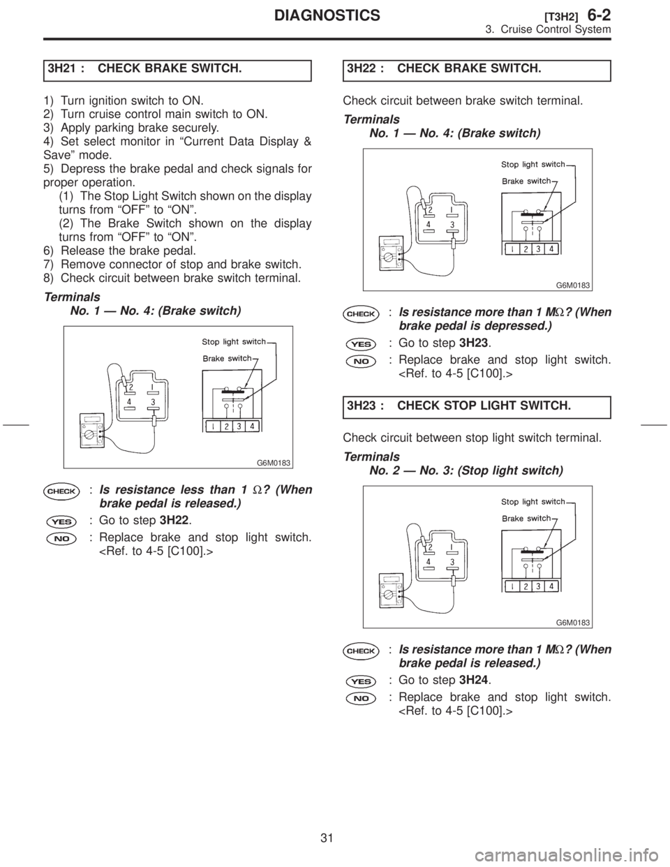
8) Check circuit between brake switch terminal.
Terminals
No. 1 Ð No. 4: (Brake switch)
G6M0183
:Is resistance less than 1W? (When
brake pedal is released.)
: Go to step3H22.
: Replace brake and stop light switch.
3H22 : CHECK BRAKE SWITCH.
Check circuit between brake switch terminal.
Terminals
No. 1 Ð No. 4: (Brake switch)
G6M0183
:Is resistance more than 1 MW? (When
brake pedal is depressed.)
: Go to step3H23.
: Replace brake and stop light switch.
3H23 : CHECK STOP LIGHT SWITCH.
Check circuit between stop light switch terminal.
Terminals
No. 2 Ð No. 3: (Stop light switch)
G6M0183
:Is resistance more than 1 MW? (When
brake pedal is released.)
: Go to step3H24.
: Replace brake and stop light switch.
31
[T3H2]6-2DIAGNOSTICS
3. Cruise Control System
Page 97 of 345
3H31 : CHECK CLUTCH SWITCH. (MT)
1) Turn ignition switch to ON.
2) Turn cruise control main switch to ON.
3) Apply parking brake securely.
4) Set select monitor in ªCurrent Data Display &
Saveº mode.
5) Depress the clutch pedal and check signal for
proper operation. (MT)
The Clutch/Inhibitor Switch shown on the display
turns from ªONº to ªOFFº.
6) Disconnect connector of clutch switch.
7) Check continuity of the clutch switch.
Terminals
No. 1 Ð No. 2:
G6M0184
:Is resistance less than 10W? (When
clutch pedal is released.)
: Go to step3H32.
: Replace clutch switch.
[C100].>3H32 : CHECK CLUTCH SWITCH. (MT)
Check continuity of the clutch switch.
Terminals
No. 1 Ð No. 2:
G6M0184
:Is resistance more than 1 MW? (When
clutch pedal is depressed.)
: Replace cruise control module.
6-2 [W12B4].>
: Replace clutch switch.
[C100].>
35
[T3H3]6-2DIAGNOSTICS
3. Cruise Control System
Page 98 of 345
3H33 : CHECK INHIBITOR SWITCH. (AT)
1) Turn ignition switch to ON.
2) Turn cruise control main switch to ON.
3) Apply parking brake securely.
4) Set select monitor in ªCurrent Data Display &
Saveº mode.
5) Set the select lever from P or N position to D
position and check signal for proper operation.
The Clutch/Inhibitor Switch shown on the display
turns from ªONº to ªOFFº.
6) Set the select lever to P or N position.
7) Disconnect connector of inhibitor switch.
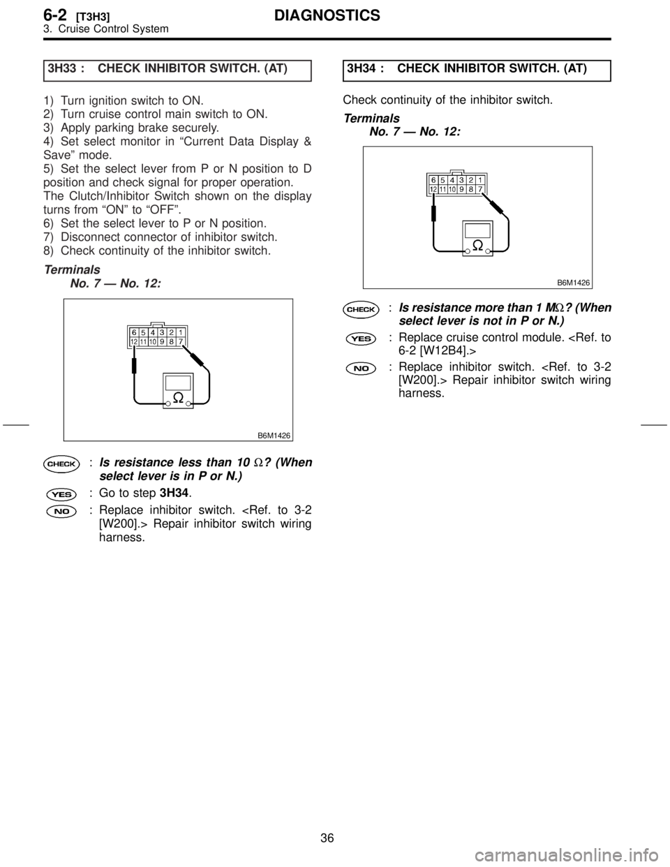
8) Check continuity of the inhibitor switch.
Terminals
No. 7 Ð No. 12:
B6M1426
:Is resistance less than 10W? (When
select lever is in P or N.)
: Go to step3H34.
: Replace inhibitor switch.
[W200].> Repair inhibitor switch wiring
harness.3H34 : CHECK INHIBITOR SWITCH. (AT)
Check continuity of the inhibitor switch.
Terminals
No. 7 Ð No. 12:
B6M1426
:Is resistance more than 1 MW? (When
select lever is not in P or N.)
: Replace cruise control module.
6-2 [W12B4].>
: Replace inhibitor switch.
[W200].> Repair inhibitor switch wiring
harness.
36
6-2[T3H3]DIAGNOSTICS
3. Cruise Control System
Page 101 of 345
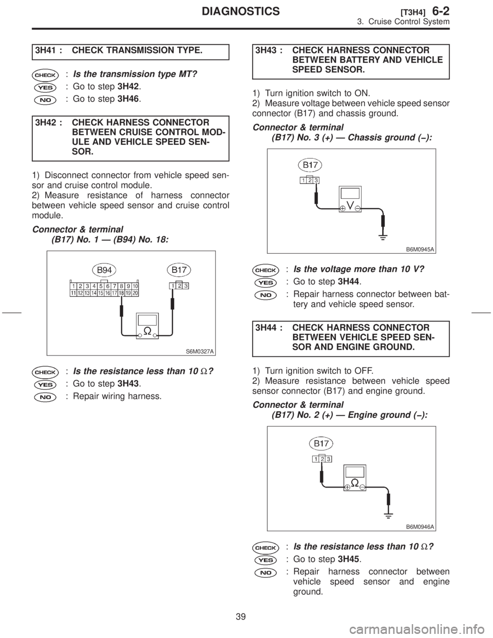
3H41 : CHECK TRANSMISSION TYPE.
:Is the transmission type MT?
: Go to step3H42.
: Go to step3H46.
3H42 : CHECK HARNESS CONNECTOR
BETWEEN CRUISE CONTROL MOD-
ULE AND VEHICLE SPEED SEN-
SOR.
1) Disconnect connector from vehicle speed sen-
sor and cruise control module.
2) Measure resistance of harness connector
between vehicle speed sensor and cruise control
module.
Connector & terminal
(B17) No. 1 Ð (B94) No. 18:
S6M0327A
:Is the resistance less than 10W?
: Go to step3H43.
: Repair wiring harness.3H43 : CHECK HARNESS CONNECTOR
BETWEEN BATTERY AND VEHICLE
SPEED SENSOR.
1) Turn ignition switch to ON.
2) Measure voltage between vehicle speed sensor
connector (B17) and chassis ground.
Connector & terminal
(B17) No. 3 (+) Ð Chassis ground (þ):
B6M0945A
:Is the voltage more than 10 V?
: Go to step3H44.
: Repair harness connector between bat-
tery and vehicle speed sensor.
3H44 : CHECK HARNESS CONNECTOR
BETWEEN VEHICLE SPEED SEN-
SOR AND ENGINE GROUND.
1) Turn ignition switch to OFF.
2) Measure resistance between vehicle speed
sensor connector (B17) and engine ground.
Connector & terminal
(B17) No. 2 (+) Ð Engine ground (þ):
B6M0946A
:Is the resistance less than 10W?
: Go to step3H45.
: Repair harness connector between
vehicle speed sensor and engine
ground.
39
[T3H4]6-2DIAGNOSTICS
3. Cruise Control System
Page 105 of 345
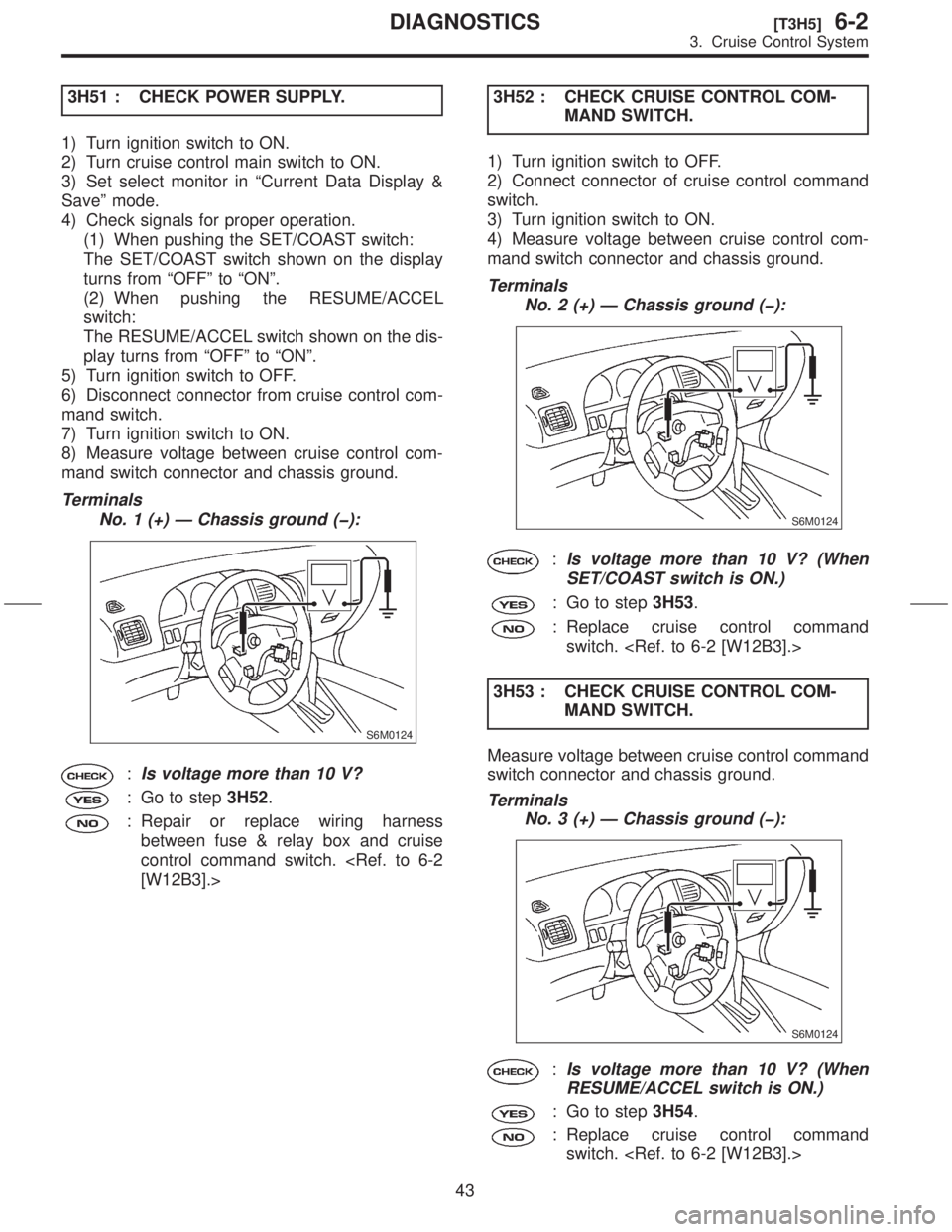
3H51 : CHECK POWER SUPPLY.
1) Turn ignition switch to ON.
2) Turn cruise control main switch to ON.
3) Set select monitor in ªCurrent Data Display &
Saveº mode.
4) Check signals for proper operation.
(1) When pushing the SET/COAST switch:
The SET/COAST switch shown on the display
turns from ªOFFº to ªONº.
(2) When pushing the RESUME/ACCEL
switch:
The RESUME/ACCEL switch shown on the dis-
play turns from ªOFFº to ªONº.
5) Turn ignition switch to OFF.
6) Disconnect connector from cruise control com-
mand switch.
7) Turn ignition switch to ON.
8) Measure voltage between cruise control com-
mand switch connector and chassis ground.
Terminals
No. 1 (+) Ð Chassis ground (þ):
S6M0124
:Is voltage more than 10 V?
: Go to step3H52.
: Repair or replace wiring harness
between fuse & relay box and cruise
control command switch.
[W12B3].>3H52 : CHECK CRUISE CONTROL COM-
MAND SWITCH.
1) Turn ignition switch to OFF.
2) Connect connector of cruise control command
switch.
3) Turn ignition switch to ON.
4) Measure voltage between cruise control com-
mand switch connector and chassis ground.
Terminals
No. 2 (+) Ð Chassis ground (þ):
S6M0124
:Is voltage more than 10 V? (When
SET/COAST switch is ON.)
: Go to step3H53.
: Replace cruise control command
switch.
3H53 : CHECK CRUISE CONTROL COM-
MAND SWITCH.
Measure voltage between cruise control command
switch connector and chassis ground.
Terminals
No. 3 (+) Ð Chassis ground (þ):
S6M0124
:Is voltage more than 10 V? (When
RESUME/ACCEL switch is ON.)
: Go to step3H54.
: Replace cruise control command
switch.
43
[T3H5]6-2DIAGNOSTICS
3. Cruise Control System
Page 106 of 345
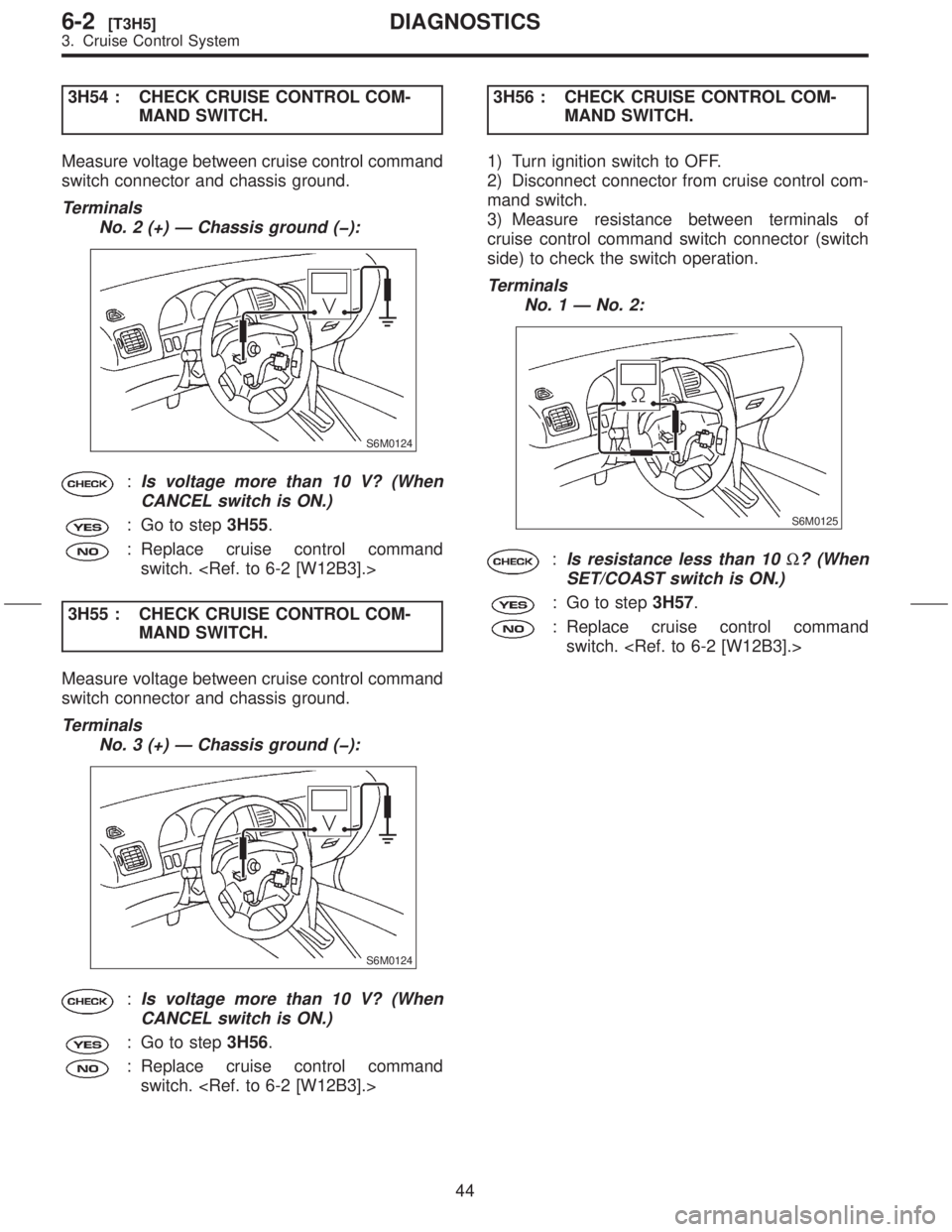
3H54 : CHECK CRUISE CONTROL COM-
MAND SWITCH.
Measure voltage between cruise control command
switch connector and chassis ground.
Terminals
No. 2 (+) Ð Chassis ground (þ):
S6M0124
:Is voltage more than 10 V? (When
CANCEL switch is ON.)
: Go to step3H55.
: Replace cruise control command
switch.
3H55 : CHECK CRUISE CONTROL COM-
MAND SWITCH.
Measure voltage between cruise control command
switch connector and chassis ground.
Terminals
No. 3 (+) Ð Chassis ground (þ):
S6M0124
:Is voltage more than 10 V? (When
CANCEL switch is ON.)
: Go to step3H56.
: Replace cruise control command
switch. 3H56 : CHECK CRUISE CONTROL COM-
MAND SWITCH.
1) Turn ignition switch to OFF.
2) Disconnect connector from cruise control com-
mand switch.
3) Measure resistance between terminals of
cruise control command switch connector (switch
side) to check the switch operation.
Terminals
No. 1 Ð No. 2:
S6M0125
:Is resistance less than 10W? (When
SET/COAST switch is ON.)
: Go to step3H57.
: Replace cruise control command
switch.
44
6-2[T3H5]DIAGNOSTICS
3. Cruise Control System