Page 146 of 345
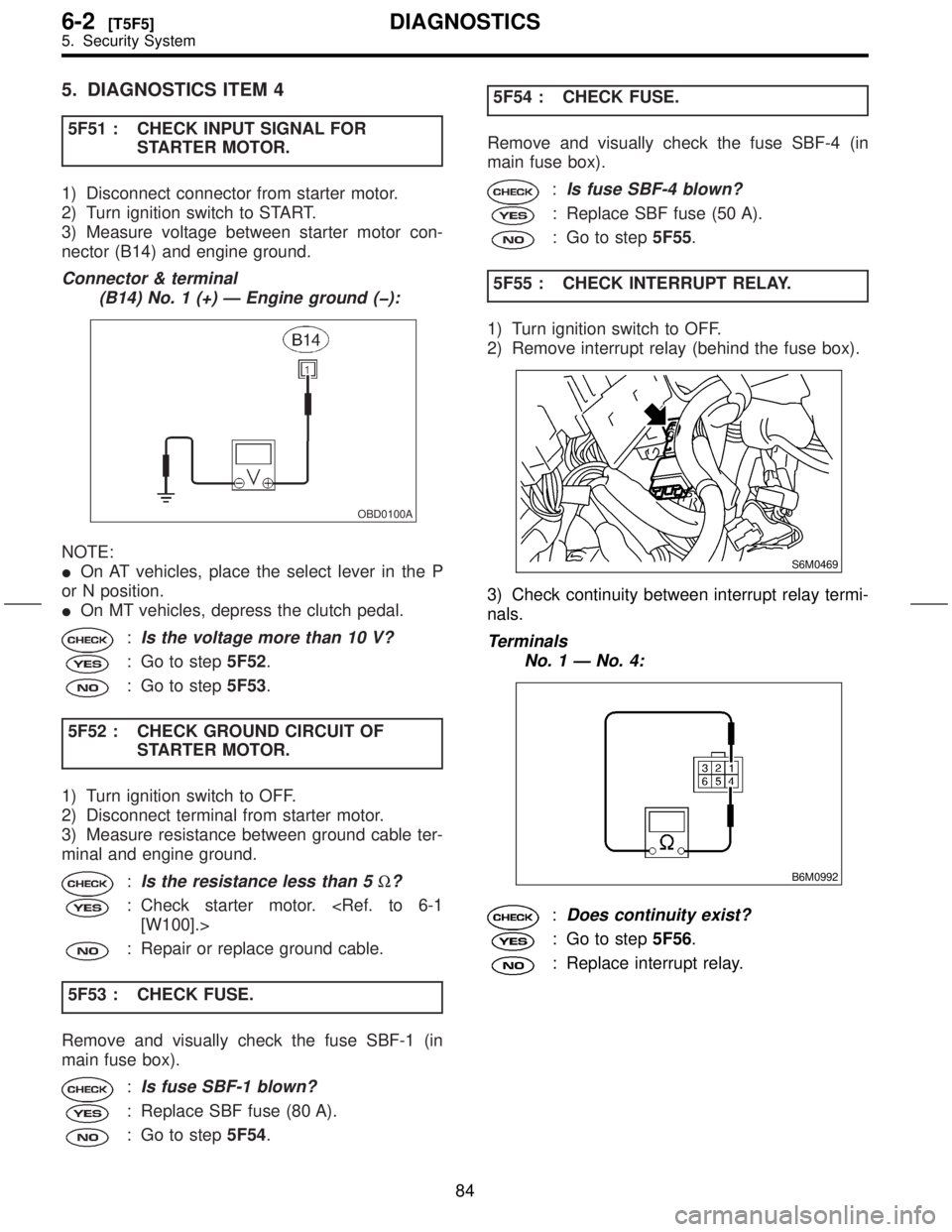
5. DIAGNOSTICS ITEM 4
5F51 : CHECK INPUT SIGNAL FOR
STARTER MOTOR.
1) Disconnect connector from starter motor.
2) Turn ignition switch to START.
3) Measure voltage between starter motor con-
nector (B14) and engine ground.
Connector & terminal
(B14) No. 1 (+) Ð Engine ground (þ):
OBD0100A
NOTE:
IOn AT vehicles, place the select lever in the P
or N position.
IOn MT vehicles, depress the clutch pedal.
:Is the voltage more than 10 V?
: Go to step5F52.
: Go to step5F53.
5F52 : CHECK GROUND CIRCUIT OF
STARTER MOTOR.
1) Turn ignition switch to OFF.
2) Disconnect terminal from starter motor.
3) Measure resistance between ground cable ter-
minal and engine ground.
:Is the resistance less than 5W?
: Check starter motor.
[W100].>
: Repair or replace ground cable.
5F53 : CHECK FUSE.
Remove and visually check the fuse SBF-1 (in
main fuse box).
:Is fuse SBF-1 blown?
: Replace SBF fuse (80 A).
: Go to step5F54.5F54 : CHECK FUSE.
Remove and visually check the fuse SBF-4 (in
main fuse box).
:Is fuse SBF-4 blown?
: Replace SBF fuse (50 A).
: Go to step5F55.
5F55 : CHECK INTERRUPT RELAY.
1) Turn ignition switch to OFF.
2) Remove interrupt relay (behind the fuse box).
S6M0469
3) Check continuity between interrupt relay termi-
nals.
Terminals
No. 1 Ð No. 4:
B6M0992
:Does continuity exist?
: Go to step5F56.
: Replace interrupt relay.
84
6-2[T5F5]DIAGNOSTICS
5. Security System
Page 147 of 345
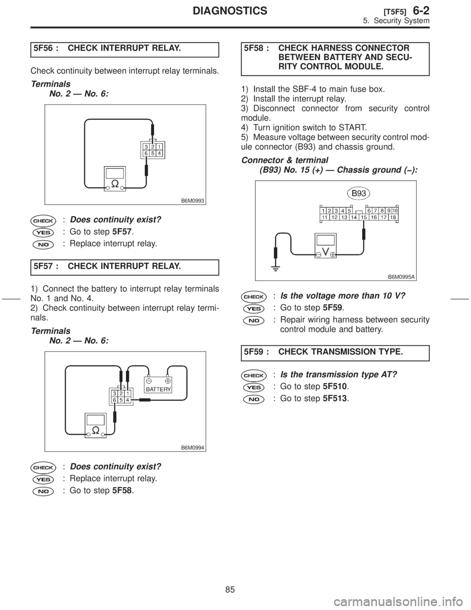
5F56 : CHECK INTERRUPT RELAY.
Check continuity between interrupt relay terminals.
Terminals
No. 2 Ð No. 6:
B6M0993
:Does continuity exist?
: Go to step5F57.
: Replace interrupt relay.
5F57 : CHECK INTERRUPT RELAY.
1) Connect the battery to interrupt relay terminals
No. 1 and No. 4.
2) Check continuity between interrupt relay termi-
nals.
Terminals
No. 2 Ð No. 6:
B6M0994
:Does continuity exist?
: Replace interrupt relay.
: Go to step5F58.5F58 : CHECK HARNESS CONNECTOR
BETWEEN BATTERY AND SECU-
RITY CONTROL MODULE.
1) Install the SBF-4 to main fuse box.
2) Install the interrupt relay.
3) Disconnect connector from security control
module.
4) Turn ignition switch to START.
5) Measure voltage between security control mod-
ule connector (B93) and chassis ground.
Connector & terminal
(B93) No. 15 (+) Ð Chassis ground (þ):
B6M0995A
:Is the voltage more than 10 V?
: Go to step5F59.
: Repair wiring harness between security
control module and battery.
5F59 : CHECK TRANSMISSION TYPE.
:Is the transmission type AT?
: Go to step5F510.
: Go to step5F513.
85
[T5F5]6-2DIAGNOSTICS
5. Security System
Page 148 of 345

5F510 : CHECK HARNESS CONNECTOR
BETWEEN INTERRUPT RELAY
AND INHIBITOR SWITCH.
1) Turn ignition switch to OFF.
2) Disconnect connector from inhibitor switch.
3) Turn ignition switch to START.
4) Measure voltage between inhibitor switch con-
nector (T7) and chassis ground.
Connector & terminal
(T7) No. 12 (+) Ð Chassis ground (þ):
B6M1425A
:Is the voltage more than 10 V?
: Go to step5F511.
: Repair wiring harness between interrupt
relay and inhibitor switch.
5F511 : CHECK INHIBITOR SWITCH.
1) Place the select lever in the P or N position.
2) Measure resistance between inhibitor switch
terminals.
Terminals
No. 7 Ð No. 12:
B6M1426
:Is the resistance less than 1W?
: Go to step5F512.
: Replace inhibitor switch.
[W200].>5F512 : CHECK HARNESS BETWEEN
INHIBITOR SWITCH AND STARTER
MOTOR.
Measure resistance between inhibitor switch con-
nector (T7) and starter motor connector (B14).
Connector & terminal
(T7) No. 7 Ð (B14) No. 1:
B6M1427A
:Is the resistance less than 10W?
: Replace security control module.
to 6-2 [W14A1].>
: Repair wiring harness between inhibitor
switch and starter motor.
5F513 : CHECK STARTER INTERLOCK
RELAY.
1) Turn ignition switch to OFF.
2) Remove starter interlock relay.
3) Check continuity between starter interlock relay
terminals.
Terminals
No. 3 Ð No. 2:
B6M1377
:Does continuity exist?
: Go to step5F514.
: Replace starter interlock relay.
86
6-2[T5F5]DIAGNOSTICS
5. Security System
Page 150 of 345
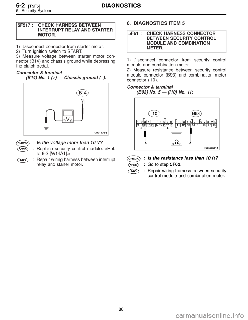
5F517 : CHECK HARNESS BETWEEN
INTERRUPT RELAY AND STARTER
MOTOR.
1) Disconnect connector from starter motor.
2) Turn ignition switch to START.
3) Measure voltage between starter motor con-
nector (B14) and chassis ground while depressing
the clutch pedal.
Connector & terminal
(B14) No. 1 (+) Ð Chassis ground (þ):
B6M1002A
:Is the voltage more than 10 V?
: Replace security control module.
to 6-2 [W14A1].>
: Repair wiring harness between interrupt
relay and starter motor.
6. DIAGNOSTICS ITEM 5
5F61 : CHECK HARNESS CONNECTOR
BETWEEN SECURITY CONTROL
MODULE AND COMBINATION
METER.
1) Disconnect connector from security control
module and combination meter.
2) Measure resistance between security control
module connector (B93) and combination meter
connector (i10).
Connector & terminal
(B93) No. 5 Ð (i10) No. 11:
S6M0465A
:Is the resistance less than 10W?
: Go to step5F62.
: Repair wiring harness between security
control module and combination meter.
88
6-2[T5F5]DIAGNOSTICS
5. Security System
Page 273 of 345
1. General
A: PRECAUTION
IIf any of the airbag system parts such as
sensors, airbag module, airbag control module and
harness are damaged or deformed, replace with
new genuine parts.
G5M0291
IWhen servicing, be sure to turn the ignition
switch off, disconnect the negative (þ) battery ter-
minal then the positive (+) terminal in advance, and
wait for more than 20 seconds before starting
work.
G5M0292
IWhen checking the system, be sure to use a
digital circuit tester. Use of an analog circuit tester
may cause the airbag to activate erroneously. Do
not directly apply the tester probe to any connec-
tor terminal of the airbag. When checking, use a
test harness.
G5M0293
G5M0294
3
[W1A0]5-5SERVICE PROCEDURE
1. General
Page 274 of 345
IDo not drop the airbag modulator parts, subject
it to high temperatures over 90ÉC (194ÉF), or apply
oil, grease, or water to it; otherwise, the internal
parts may be damaged and its reliability greatly
lowered.
G5M0295
IIf any damage or open is found on the SRS air-
bag system wire harness, do not attempt to repair
using soldering, etc. Be sure to replace the faulty
harness with a new genuine part.
G5M0296
IInstall the wire harness securely with the speci-
fied clips so as to avoid interference or jamming
with other parts.
G5M0297
IBefore connecting the airbag system to ground,
make sure that the grounding terminal is free from
paint and contamination.
IDo not allow water or oil to come in contact with
the connector terminals. Do not touch the connec-
tor terminals.
G5M0298
IWhen connecting or disconnecting airbag
connector, make sure ignition switch is OFF.
4
5-5[W1A0]SERVICE PROCEDURE
1. General
Page 275 of 345
2. Inspection and Replacement
Standards
A: VEHICLES WHICH BECOME
INVOLVED IN A COLLISION
If the vehicle equipped with an SRS airbag system
is damaged in a collision, the airbag system parts
must be checked and replaced in accordance with
the following standards:
IAfter faulty parts are replaced, the warning light
operation must be checked.
IWhen the ignition switch is turned ON, it lights
up for about 7 seconds and then it goes out for at
least 30 seconds.
IThe trouble code stored in memory must be
erased after the check.
B: AIRBAG MODULE (DRIVER AND
PASSENGER)
1. INSPECTION STANDARD
IThe vehicle damaged in a collision (regardless
of whether or not airbag is deployed).
IThe designated trouble code is output during
self-diagnosis.
2. REPLACEMENT STANDARD
IAirbag is deployed.
IThe pad surface is scratched or cracked.
IHarness and/or connector is deformed or
cracked, their circuits are broken, lead wire is
exposed, etc.
IMounting bracket is cracked or deformed.
IThe module surface is fouled with foreign mat-
ter. (grease, oil, water, cleaning solvent, etc.)
IAirbag module dropped to the floor/ground.
IAirbag module determined as faulty during self-
diagnosis.
C: AIRBAG MODULE (SIDE)
1. INSPECTION STANDARD
IThe vehicle damaged in a side collision (regard-
less of whether or not airbag is deployed).
IThe designated trouble code is output during
self-diagnosis.
2. REPLACEMENT STANDARD
ISide airbag is deployed.
IThe front seat assembly is damaged or
deformed.
IHarness and/or connector is deformed or
cracked, their circuits are broken, lead wire is
exposed, etc.
IMounting bracket is cracked or deformed.ISide airbag module determined as faulty during
self-diagnosis.
D: MAIN HARNESS
1. INSPECTION STANDARD
IA vehicle damaged in a collision (regardless of
whether or not airbag is deployed).
IThe designated trouble code is output during
self-diagnosis.
2. REPLACEMENT STANDARD
IHarness circuit is broken, lead wire is exposed,
corrugated tube is cracked, etc.
IConnector is scratched or cracked.
IThe designated trouble code is output during
self-diagnosis.
E: AIRBAG CONTROL MODULE
1. INSPECTION STANDARD
IA vehicle damaged in a collision (regardless of
whether or not airbag is deployed).
IThe designated trouble code is output during
self-diagnosis.
2. REPLACEMENT STANDARD
IControl module is cracked or deformed.
IMounting bracket is cracked or deformed.
IConnector is scratched or cracked.
IControl module dropped to the floor/ground.
IControl module determined as faulty during
diagnostics.
IFront or side airbag is deployed.
F: ROLL CONNECTOR
1. INSPECTION STANDARD
IA vehicle damaged in a collision (regardless of
whether or not airbag is deployed).
IThe designated trouble code is output during
self-diagnosis.
2. REPLACEMENT STANDARD
ICombination switch or steering roll connector is
deformed or cracked.
5
[W2F2]5-5SERVICE PROCEDURE
2. Inspection and Replacement Standards
Page 284 of 345
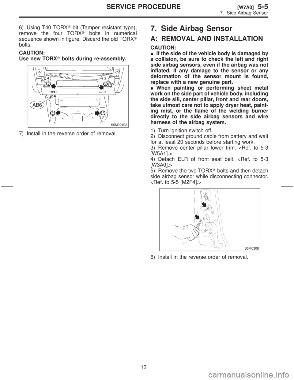
6) Using T40 TORXTbit (Tamper resistant type),
remove the four TORXTbolts in numerical
sequence shown in figure. Discard the old TORXT
bolts.
CAUTION:
Use new TORXTbolts during re-assembly.
S5M0219A
7) Install in the reverse order of removal.
7. Side Airbag Sensor
A: REMOVAL AND INSTALLATION
CAUTION:
IIf the side of the vehicle body is damaged by
a collision, be sure to check the left and right
side airbag sensors, even if the airbag was not
inflated. If any damage to the sensor or any
deformation of the sensor mount is found,
replace with a new genuine part.
IWhen painting or performing sheet metal
work on the side part of vehicle body, including
the side sill, center pillar, front and rear doors,
take utmost care not to apply dryer heat, paint-
ing mist, or the flame of the welding burner
directly to the side airbag sensors and wire
harness of the airbag system.
1) Turn ignition switch off.
2) Disconnect ground cable from battery and wait
for at least 20 seconds before starting work.
3) Remove center pillar lower trim.
[W5A1].>
4) Detach ELR of front seat belt.
[W3A0].>
5) Remove the two TORXTbolts and then detach
side airbag sensor while disconnecting connector.
S5M0308
6) Install in the reverse order of removal.
13
[W7A0]5-5SERVICE PROCEDURE
7. Side Airbag Sensor