Page 150 of 345

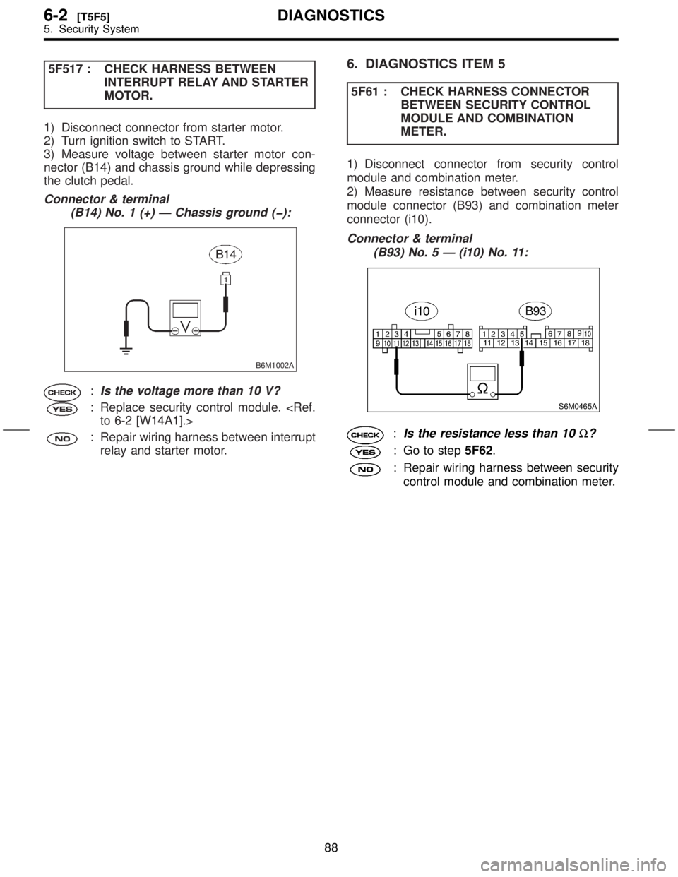
5F517 : CHECK HARNESS BETWEEN
INTERRUPT RELAY AND STARTER
MOTOR.
1) Disconnect connector from starter motor.
2) Turn ignition switch to START.
3) Measure voltage between starter motor con-
nector (B14) and chassis ground while depressing
the clutch pedal.
Connector & terminal
(B14) No. 1 (+) Ð Chassis ground (þ):
B6M1002A
:Is the voltage more than 10 V?
: Replace security control module.
to 6-2 [W14A1].>
: Repair wiring harness between interrupt
relay and starter motor.
6. DIAGNOSTICS ITEM 5
5F61 : CHECK HARNESS CONNECTOR
BETWEEN SECURITY CONTROL
MODULE AND COMBINATION
METER.
1) Disconnect connector from security control
module and combination meter.
2) Measure resistance between security control
module connector (B93) and combination meter
connector (i10).
Connector & terminal
(B93) No. 5 Ð (i10) No. 11:
S6M0465A
:Is the resistance less than 10W?
: Go to step5F62.
: Repair wiring harness between security
control module and combination meter.
88
6-2[T5F5]DIAGNOSTICS
5. Security System
Page 151 of 345
5F62 : CHECK HARNESS CONNECTOR
BETWEEN FRONT DOOR SWITCH
RH AND COMBINATION METER.
1) Disconnect connector from front door switch
RH.
2) Measure resistance between front door switch
RH connector (R12) and combination meter con-
nector (i10).
Connector & terminal
(R12) No. 1 Ð (i10) No. 11:
S6M0470A
:Is the resistance less than 10W?
: Go to step5F63.
: Repair wiring harness between front
door switch RH and combination meter.5F63 : CHECK COMBINATION METER CIR-
CUIT.
1) Remove combination meter.
2) Measure resistance between combination
meter terminals.
Terminals
No. 11 Ð No. 12:
S6M0468
:Is the resistance less than 10W?
: Replace security control module.
to 6-2 [W14A1].>
: Repair or replace combination meter.
89
[T5F6]6-2DIAGNOSTICS
5. Security System
Page 152 of 345

7. DIAGNOSTIC ITEM 6
5F71 : CHECK HARNESS CONNECTOR
BETWEEN SECURITY CONTROL
MODULE AND COMBINATION
METER.
1) Disconnect connector from security control
module and combination meter.
2) Measure resistance between security control
module connector (B93) and combination meter
connector (i10).
Connector & terminal
(B93) No. 5 Ð (i10) No. 11:
S6M0465A
:Is the resistance less than 10W?
: Go to step5F72.
: Repair wiring harness between security
control module and combination meter.5F72 : CHECK HARNESS CONNECTOR
BETWEEN REAR DOOR SWITCH LH
AND COMBINATION METER.
1) Disconnect connector from rear door switch LH.
2) Measure resistance between rear door switch
LH connector (R22) and combination meter con-
nector (i10).
Connector & terminal
(R22) No. 1 Ð (i10) No. 11:
S6M0471A
:Is the resistance less than 10W?
: Go to step5F73.
: Repair wiring harness between rear
door switch LH and combination meter.
5F73 : CHECK COMBINATION METER CIR-
CUIT.
1) Remove combination meter.
[W8A0].>
2) Measure resistance between combination
meter terminals.
Terminals
No. 11 Ð No. 12:
S6M0468
:Is the resistance less than 10W?
: Replace security control module.
to 6-2 [W14A1].>
: Repair or replace combination meter.
90
6-2[T5F7]DIAGNOSTICS
5. Security System
Page 153 of 345
8. DIAGNOSTIC ITEM 7
5F81 : CHECK HARNESS CONNECTOR
BETWEEN SECURITY CONTROL
MODULE AND COMBINATION
METER.
1) Disconnect connector from security control
module and combination meter.
2) Measure resistance between security control
module connector (B93) and combination meter
connector (i10).
Connector & terminal
(B93) No. 5 Ð (i10) No. 11:
S6M0465A
:Is the resistance less than 10W?
: Go to step5F82.
: Repair wiring harness between security
control module and combination meter.5F82 : CHECK HARNESS CONNECTOR
BETWEEN REAR DOOR SWITCH RH
AND COMBINATION METER.
1) Disconnect connector from rear door switch
RH.
2) Measure resistance between rear door switch
RH connector (R16) and combination meter con-
nector (i10).
Connector & terminal
(R16) No. 1 Ð (i10) No. 11:
S6M0472A
:Is the resistance less than 10W?
: Go to step5F83.
: Repair wiring harness between rear
door switch RH and combination meter.
91
[T5F8]6-2DIAGNOSTICS
5. Security System
Page 154 of 345
5F83 : CHECK COMBINATION METER CIR-
CUIT.
1) Remove combination meter.
[W8A0].>
2) Measure resistance between combination
meter terminals.
Terminals
No. 11 Ð No. 12:
S6M0468
:Is the resistance less than 10W?
: Replace security control module.
to 6-2 [W14A1].>
: Repair or replace combination meter.
9. DIAGNOSTIC ITEM 8
5F91 : CHECK HARNESS CONNECTOR
BETWEEN REAR GATE LATCH
SWITCH AND SECURITY CONTROL
MODULE.
1) Disconnect connector from rear gate latch
switch and security control module.
2) Measure resistance between rear gate latch
switch connector (D46) and security control mod-
ule connector (B93).
Connector & terminal
(D46) No. 1 Ð (B93) No. 5:
S6M0473A
:Is the resistance less than 10W?
: Go to step5F92.
: Repair wiring harness between rear
gate latch switch and security control
module.
92
6-2[T5F8]DIAGNOSTICS
5. Security System
Page 155 of 345
5F92 : CHECK HARNESS CONNECTOR
BETWEEN REAR GATE LATCH
SWITCH AND CHASSIS GROUND.
Measure resistance between rear gate latch switch
connector (D46) and chassis ground.
Connector & terminal
(D46) No. 2 (+) Ð Chassis ground (þ):
B6M1010A
:Is the resistance less than 10W?
: Go to step5F93.
: Repair wiring harness between rear
gate latch switch and chassis ground.
5F93 : CHECK REAR GATE LATCH
SWITCH.
Measure resistance between rear gate latch switch
terminals.
Terminals
No. 1 Ð No. 2:
B6M1386
:Is the resistance less than 10W?
: Go to step5F94.
: Replace rear gate latch switch.5F94 : CHECK REAR GATE LATCH
SWITCH.
Measure resistance between rear gate latch switch
terminals while pushing the switch.
Terminals
No. 1 Ð No. 2:
B6M1386
:Is the resistance less than 10W?
: Replace rear gate latch switch.
: Replace security control module.
to 6-2 [W14A1].>
93
[T5F9]6-2DIAGNOSTICS
5. Security System
Page 156 of 345
![SUBARU FORESTER 1999 Service Repair Manual 10. DIAGNOSTIC ITEM 9
5F101 : CHECK SECURITY CONTROL
MODULE.
Check and ensure that security control module is
installed on the bracket. <Ref. to 6-2 [W14A1].>
:Is the security control module
securely SUBARU FORESTER 1999 Service Repair Manual 10. DIAGNOSTIC ITEM 9
5F101 : CHECK SECURITY CONTROL
MODULE.
Check and ensure that security control module is
installed on the bracket. <Ref. to 6-2 [W14A1].>
:Is the security control module
securely](/manual-img/17/57427/w960_57427-155.png)
10. DIAGNOSTIC ITEM 9
5F101 : CHECK SECURITY CONTROL
MODULE.
Check and ensure that security control module is
installed on the bracket.
:Is the security control module
securely installed?
: Go to step5F102.
: Securely install security control module.
5F102 : ADJUST SENSITIVITY.
1) Remove security control module.
[W14A1].>
2) Adjust the sensitivity adjust screw in security
control module.
NOTE:
After adjusting, be sure to plug the adjust screw
hole.
B6M1389A
3) Install security control module.
[W14A1].>
4) Perform impact sensitivity test.
:Is sensitivity adjustment possible?
: Impact sensitivity is normal.
: Replace security control module.
to 6-2 [W14A1].>
11. DIAGNOSTIC ITEM 10
5F111 : CHECK PASSIVE ARM CIRCUIT.
1) Connect connector (B183) and (B184) at driver
side front lower pillar.
2) Disconnect connector from security control
module.
3) Measure resistance between security control
module (B93) and chassis ground.
Connector & terminal
(B93) No. 3 (+) Ð Chassis ground (þ):
B6M1013A
:Is the resistance less than 10W?
: Replace security control module.
to 6-2 [W14A1].>
: Repair wiring harness between security
control module and chassis ground.
94
6-2[T5F10]DIAGNOSTICS
5. Security System
Page 185 of 345

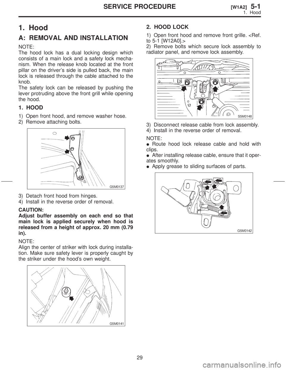
1. Hood
A: REMOVAL AND INSTALLATION
NOTE:
The hood lock has a dual locking design which
consists of a main lock and a safety lock mecha-
nism. When the release knob located at the front
pillar on the driver's side is pulled back, the main
lock is released through the cable attached to the
knob.
The safety lock can be released by pushing the
lever protruding above the front grill while opening
the hood.
1. HOOD
1) Open front hood, and remove washer hose.
2) Remove attaching bolts.
G5M0137
3) Detach front hood from hinges.
4) Install in the reverse order of removal.
CAUTION:
Adjust buffer assembly on each end so that
main lock is applied securely when hood is
released from a height of approx. 20 mm (0.79
in).
NOTE:
Align the center of striker with lock during installa-
tion. Make sure safety lever is properly caught by
the striker under the hood's own weight.
G5M0141
2. HOOD LOCK
1) Open front hood and remove front grille.
to 5-1 [W12A0].>
2) Remove bolts which secure lock assembly to
radiator panel, and remove lock assembly.
S5M0148
3) Disconnect release cable from lock assembly.
4) Install in the reverse order of removal.
NOTE:
IRoute hood lock release cable and hold with
clips.
IAfter installing release cable, ensure that it oper-
ates smoothly.
IApply grease to sliding surfaces of parts.
G5M0142
29
[W1A2]5-1SERVICE PROCEDURE
1. Hood