Page 208 of 345

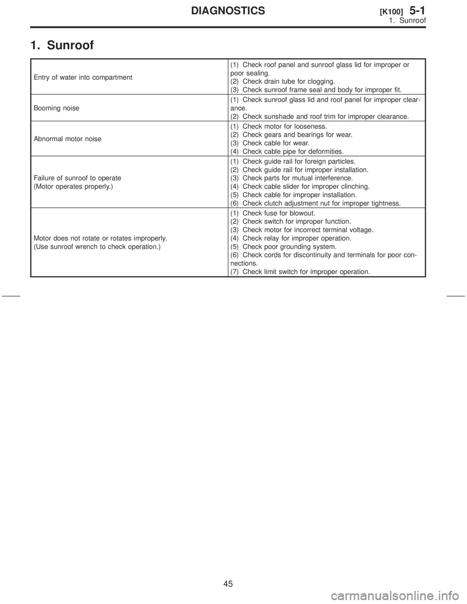
1. Sunroof
Entry of water into compartment(1) Check roof panel and sunroof glass lid for improper or
poor sealing.
(2) Check drain tube for clogging.
(3) Check sunroof frame seal and body for improper fit.
Booming noise(1) Check sunroof glass lid and roof panel for improper clear-
ance.
(2) Check sunshade and roof trim for improper clearance.
Abnormal motor noise(1) Check motor for looseness.
(2) Check gears and bearings for wear.
(3) Check cable for wear.
(4) Check cable pipe for deformities.
Failure of sunroof to operate
(Motor operates properly.)(1) Check guide rail for foreign particles.
(2) Check guide rail for improper installation.
(3) Check parts for mutual interference.
(4) Check cable slider for improper clinching.
(5) Check cable for improper installation.
(6) Check clutch adjustment nut for improper tightness.
Motor does not rotate or rotates improperly.
(Use sunroof wrench to check operation.)(1) Check fuse for blowout.
(2) Check switch for improper function.
(3) Check motor for incorrect terminal voltage.
(4) Check relay for improper operation.
(5) Check poor grounding system.
(6) Check cords for discontinuity and terminals for poor con-
nections.
(7) Check limit switch for improper operation.
45
[K100]5-1DIAGNOSTICS
1. Sunroof
Page 325 of 345

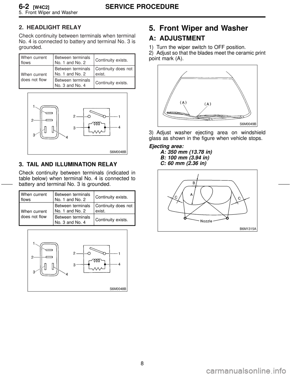
2. HEADLIGHT RELAY
Check continuity between terminals when terminal
No. 4 is connected to battery and terminal No. 3 is
grounded.
When current
flowsBetween terminals
No. 1 and No. 2Continuity exists.
When current
does not flowBetween terminals
No. 1 and No. 2Continuity does not
exist.
Between terminals
No. 3 and No. 4Continuity exists.
S6M0048B
3. TAIL AND ILLUMINATION RELAY
Check continuity between terminals (indicated in
table below) when terminal No. 4 is connected to
battery and terminal No. 3 is grounded.
When current
flowsBetween terminals
No. 1 and No. 2Continuity exists.
When current
does not flowBetween terminals
No. 1 and No. 2Continuity does not
exist.
Between terminals
No. 3 and No. 4Continuity exists.
S6M0048B
5. Front Wiper and Washer
A: ADJUSTMENT
1) Turn the wiper switch to OFF position.
2) Adjust so that the blades meet the ceramic print
point mark (A).
S6M0049B
3) Adjust washer ejecting area on windshield
glass as shown in the figure when vehicle stops.
Ejecting area:
A: 350 mm (13.78 in)
B: 100 mm (3.94 in)
C: 60 mm (2.36 in)
B6M1315A
8
6-2[W4C2]SERVICE PROCEDURE
5. Front Wiper and Washer
Page 326 of 345

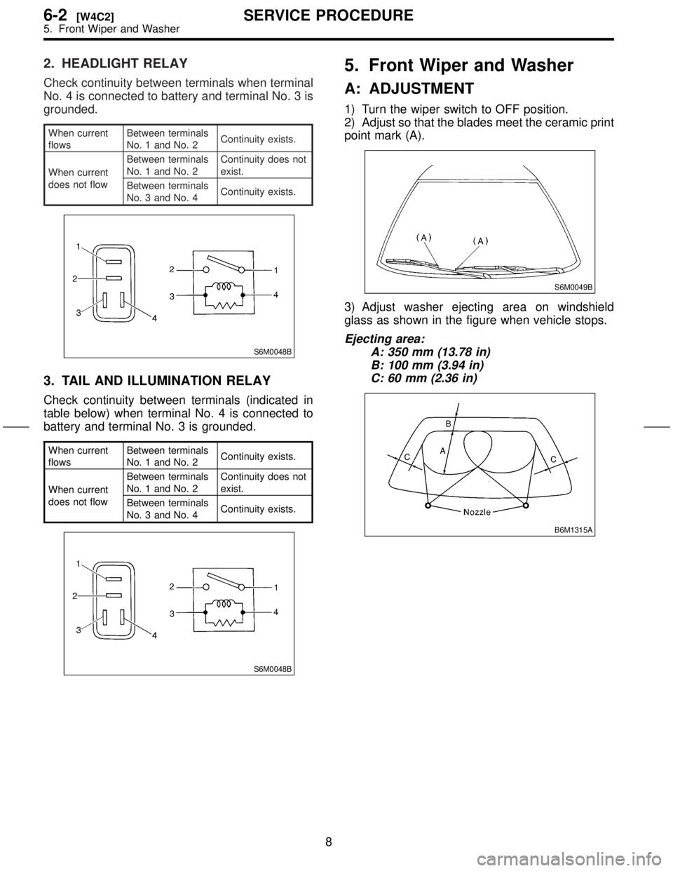
2. HEADLIGHT RELAY
Check continuity between terminals when terminal
No. 4 is connected to battery and terminal No. 3 is
grounded.
When current
flowsBetween terminals
No. 1 and No. 2Continuity exists.
When current
does not flowBetween terminals
No. 1 and No. 2Continuity does not
exist.
Between terminals
No. 3 and No. 4Continuity exists.
S6M0048B
3. TAIL AND ILLUMINATION RELAY
Check continuity between terminals (indicated in
table below) when terminal No. 4 is connected to
battery and terminal No. 3 is grounded.
When current
flowsBetween terminals
No. 1 and No. 2Continuity exists.
When current
does not flowBetween terminals
No. 1 and No. 2Continuity does not
exist.
Between terminals
No. 3 and No. 4Continuity exists.
S6M0048B
5. Front Wiper and Washer
A: ADJUSTMENT
1) Turn the wiper switch to OFF position.
2) Adjust so that the blades meet the ceramic print
point mark (A).
S6M0049B
3) Adjust washer ejecting area on windshield
glass as shown in the figure when vehicle stops.
Ejecting area:
A: 350 mm (13.78 in)
B: 100 mm (3.94 in)
C: 60 mm (2.36 in)
B6M1315A
8
6-2[W4C2]SERVICE PROCEDURE
5. Front Wiper and Washer
Page 332 of 345
3. REAR WIPER RELAY
1) Connect battery to terminal No. 1 and ground
terminal No. 2.
2) Check continuity between terminals.
When current
flowsBetween terminals
No. 3 and No. 4Continuity does
not exist.
Between terminals
No. 3 and No. 5Continuity exists.
When current
does not flowBetween terminals
No. 3 and No. 4Continuity exists.
Between terminals
No. 3 and No. 5Continuity does
not exist.
Between terminals
No. 1 and No. 2Continuity exists.
S6M0075B
7. Rear Window Defogger
A: INSPECTION
1. HEAT WIRES
1) Start the engine so that battery is being
charged.
2) Turn defogger switch to ON.
3) Check each heat wire at its center position for
discontinuity by setting direct current voltmeter.
NOTE:
INormal indication is about 6 volts.
G6M0135
IWhen measuring voltage, wind a piece of tin foil
around the tip of the tester probe and press the foil
against the wire with your finger.
G6M0136
14
6-2[W6C3]SERVICE PROCEDURE
7. Rear Window Defogger
Page 333 of 345
3. REAR WIPER RELAY
1) Connect battery to terminal No. 1 and ground
terminal No. 2.
2) Check continuity between terminals.
When current
flowsBetween terminals
No. 3 and No. 4Continuity does
not exist.
Between terminals
No. 3 and No. 5Continuity exists.
When current
does not flowBetween terminals
No. 3 and No. 4Continuity exists.
Between terminals
No. 3 and No. 5Continuity does
not exist.
Between terminals
No. 1 and No. 2Continuity exists.
S6M0075B
7. Rear Window Defogger
A: INSPECTION
1. HEAT WIRES
1) Start the engine so that battery is being
charged.
2) Turn defogger switch to ON.
3) Check each heat wire at its center position for
discontinuity by setting direct current voltmeter.
NOTE:
INormal indication is about 6 volts.
G6M0135
IWhen measuring voltage, wind a piece of tin foil
around the tip of the tester probe and press the foil
against the wire with your finger.
G6M0136
14
6-2[W6C3]SERVICE PROCEDURE
7. Rear Window Defogger
Page:
< prev 1-8 9-16 17-24