Page 127 of 345

4F28 : CHECK RESISTANCE BETWEEN
HORN RELAY AND KEYLESS
ENTRY CONTROL MODULE.
1) Disconnect connector from main fuse box and
keyless entry control module.
2) Measure resistance between keyless entry con-
trol module connector (B176) and main fuse box
connector (F37).
Connector & terminal
(B176) No. 12 Ð (F37) No. 4:
B6M1352A
:Is the resistance less than 10W?
: Replace keyless entry control module.
: Repair wiring harness between main
fuse box and keyless entry control mod-
ule.
3. DIAGNOSTICS ITEM 2
4F31 : CHECK FUSE.
Remove and visually check the fuse No. 2 (in main
fuse box).
:Is fuse No. 2 blown?
: Replace fuse (15 A).
: Go to step4F32.
4F32 : CHECK ROOM LIGHT BULB.
Remove and visually check the room light bulb.
:Is the bulb blown?
: Replace bulb.
: Go to step4F33.
4F33 : CHECK ROOM LIGHT SWITCH.
1) Remove room light.
2) Measure resistance of room light switch termi-
nal at the middle position.
Terminals
No. 2 Ð No. 3:
B6M0960A
:Is the resistance less than 1W?
: Repair or replace room light.
: Go to step4F34.
65
[T4F3]6-2DIAGNOSTICS
4. Keyless Entry System
Page 133 of 345
C: ELECTRICAL COMPONENTS LOCATION
S6M0454A
(1) Horn
(2) Keyless entry control module
(3) Security control module (under
console box)
(4) Security indicator light (in combi-
nation meter)(5) Horn relay (in main fuse box)
(6) Rear gate latch switch
(7) Interrupt relay (behind the fuse
box)
(8) Door switch(9) Passive arm connector (on driver
side front lower pillar)
71
[T5C0]6-2DIAGNOSTICS
5. Security System
Page 136 of 345
E: CONTROL MODULE I/O SIGNAL
B6M0972
Content Terminal No. Measuring condition
Empty 1 Ð
Ignition switch (ON) 2 (INPUT) Battery voltage is present when ignition switch is turned ON.
Passive arm 3 Ð
Empty 4 Ð
Door switch and rear gate latch
switch5 (INPUT) 0 V is present when any door is open.
Empty 6 Ð
Keyless entry control module 7 Ð
Keyless entry control module 8 Ð
Security indicator light 9 (OUTPUT) 0 V is present when activating the alarm operation.
Keyless entry control module 10 Ð
Power supply for clearance light
(Back-up)11 Battery voltage is constantly present.
Clearance light 12 (OUTPUT) Battery voltage is present when activating the alarm operation.
Power supply (Back-up) 13 Battery voltage is constantly present.
Ground 14 Ð
Interrupt relay 15 (OUTPUT) 0 V is present when activating the alarm operation.
Empty 16 Ð
Empty 17 Ð
Empty 18 Ð
74
6-2[T5E0]DIAGNOSTICS
5. Security System
Page 146 of 345

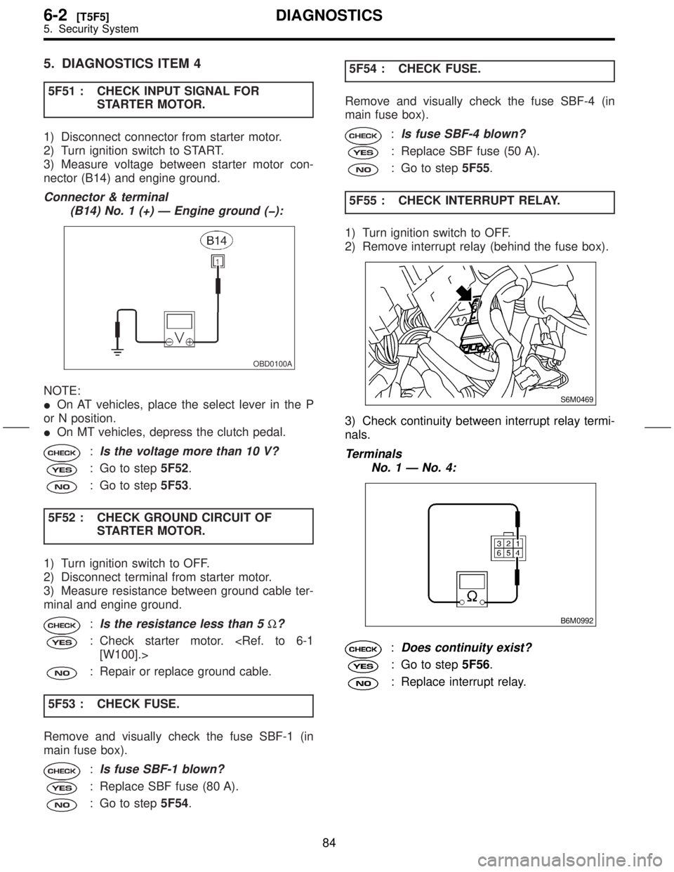
5. DIAGNOSTICS ITEM 4
5F51 : CHECK INPUT SIGNAL FOR
STARTER MOTOR.
1) Disconnect connector from starter motor.
2) Turn ignition switch to START.
3) Measure voltage between starter motor con-
nector (B14) and engine ground.
Connector & terminal
(B14) No. 1 (+) Ð Engine ground (þ):
OBD0100A
NOTE:
IOn AT vehicles, place the select lever in the P
or N position.
IOn MT vehicles, depress the clutch pedal.
:Is the voltage more than 10 V?
: Go to step5F52.
: Go to step5F53.
5F52 : CHECK GROUND CIRCUIT OF
STARTER MOTOR.
1) Turn ignition switch to OFF.
2) Disconnect terminal from starter motor.
3) Measure resistance between ground cable ter-
minal and engine ground.
:Is the resistance less than 5W?
: Check starter motor.
[W100].>
: Repair or replace ground cable.
5F53 : CHECK FUSE.
Remove and visually check the fuse SBF-1 (in
main fuse box).
:Is fuse SBF-1 blown?
: Replace SBF fuse (80 A).
: Go to step5F54.5F54 : CHECK FUSE.
Remove and visually check the fuse SBF-4 (in
main fuse box).
:Is fuse SBF-4 blown?
: Replace SBF fuse (50 A).
: Go to step5F55.
5F55 : CHECK INTERRUPT RELAY.
1) Turn ignition switch to OFF.
2) Remove interrupt relay (behind the fuse box).
S6M0469
3) Check continuity between interrupt relay termi-
nals.
Terminals
No. 1 Ð No. 4:
B6M0992
:Does continuity exist?
: Go to step5F56.
: Replace interrupt relay.
84
6-2[T5F5]DIAGNOSTICS
5. Security System
Page 147 of 345

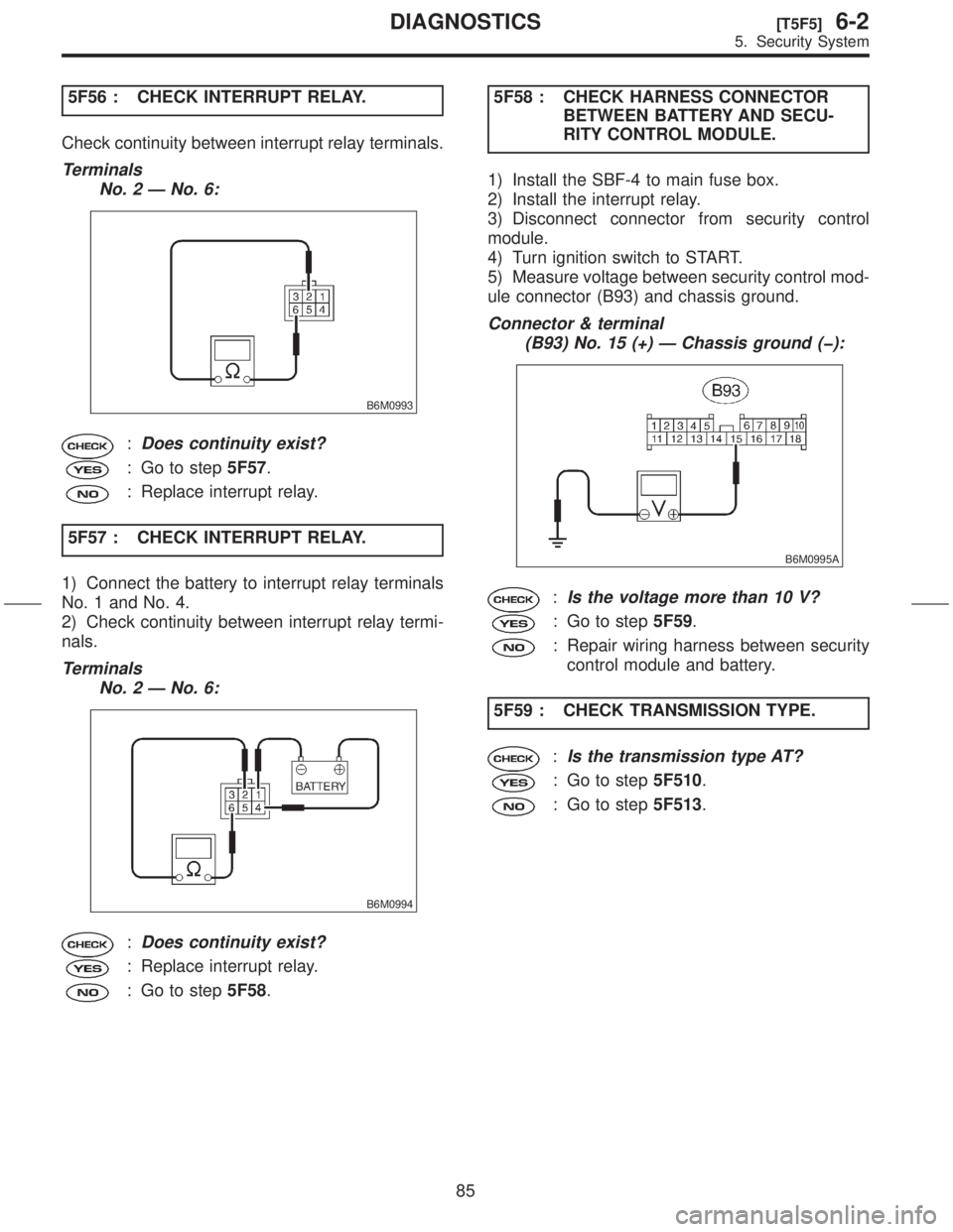
5F56 : CHECK INTERRUPT RELAY.
Check continuity between interrupt relay terminals.
Terminals
No. 2 Ð No. 6:
B6M0993
:Does continuity exist?
: Go to step5F57.
: Replace interrupt relay.
5F57 : CHECK INTERRUPT RELAY.
1) Connect the battery to interrupt relay terminals
No. 1 and No. 4.
2) Check continuity between interrupt relay termi-
nals.
Terminals
No. 2 Ð No. 6:
B6M0994
:Does continuity exist?
: Replace interrupt relay.
: Go to step5F58.5F58 : CHECK HARNESS CONNECTOR
BETWEEN BATTERY AND SECU-
RITY CONTROL MODULE.
1) Install the SBF-4 to main fuse box.
2) Install the interrupt relay.
3) Disconnect connector from security control
module.
4) Turn ignition switch to START.
5) Measure voltage between security control mod-
ule connector (B93) and chassis ground.
Connector & terminal
(B93) No. 15 (+) Ð Chassis ground (þ):
B6M0995A
:Is the voltage more than 10 V?
: Go to step5F59.
: Repair wiring harness between security
control module and battery.
5F59 : CHECK TRANSMISSION TYPE.
:Is the transmission type AT?
: Go to step5F510.
: Go to step5F513.
85
[T5F5]6-2DIAGNOSTICS
5. Security System
Page 148 of 345

5F510 : CHECK HARNESS CONNECTOR
BETWEEN INTERRUPT RELAY
AND INHIBITOR SWITCH.
1) Turn ignition switch to OFF.
2) Disconnect connector from inhibitor switch.
3) Turn ignition switch to START.
4) Measure voltage between inhibitor switch con-
nector (T7) and chassis ground.
Connector & terminal
(T7) No. 12 (+) Ð Chassis ground (þ):
B6M1425A
:Is the voltage more than 10 V?
: Go to step5F511.
: Repair wiring harness between interrupt
relay and inhibitor switch.
5F511 : CHECK INHIBITOR SWITCH.
1) Place the select lever in the P or N position.
2) Measure resistance between inhibitor switch
terminals.
Terminals
No. 7 Ð No. 12:
B6M1426
:Is the resistance less than 1W?
: Go to step5F512.
: Replace inhibitor switch.
[W200].>5F512 : CHECK HARNESS BETWEEN
INHIBITOR SWITCH AND STARTER
MOTOR.
Measure resistance between inhibitor switch con-
nector (T7) and starter motor connector (B14).
Connector & terminal
(T7) No. 7 Ð (B14) No. 1:
B6M1427A
:Is the resistance less than 10W?
: Replace security control module.
to 6-2 [W14A1].>
: Repair wiring harness between inhibitor
switch and starter motor.
5F513 : CHECK STARTER INTERLOCK
RELAY.
1) Turn ignition switch to OFF.
2) Remove starter interlock relay.
3) Check continuity between starter interlock relay
terminals.
Terminals
No. 3 Ð No. 2:
B6M1377
:Does continuity exist?
: Go to step5F514.
: Replace starter interlock relay.
86
6-2[T5F5]DIAGNOSTICS
5. Security System
Page 149 of 345
5F514 : CHECK STARTER INTERLOCK
RELAY.
Check continuity between starter interlock relay
terminals.
Terminals
No. 1 Ð No. 4:
B6M1378
:Does continuity exist?
: Replace starter interlock relay.
: Go to step5F515.
5F515 : CHECK STARTER INTERLOCK
RELAY.
1) Connect the battery to starter interlock relay ter-
minals No. 3 and No. 2.
2) Check continuity between starter interlock relay
terminals.
Terminals
No. 1 Ð No. 4:
B6M1379
:Does continuity exist?
: Go to step5F516.
: Replace starter interlock relay.5F516 : CHECK CLUTCH SWITCH.
1) Install starter interlock relay.
2) Measure resistance between clutch switch con-
nector (B106) and (B107) terminals while depress-
ing the clutch pedal.
Connector & terminal
With cruise control
(B107) No. 1 Ð No. 2:
Without cruise control
(B106) No. 1 Ð No. 2:
B2M0518A
:Is the resistance less than 10W?
: Go to step5F517.
: Replace clutch switch.
87
[T5F5]6-2DIAGNOSTICS
5. Security System
Page 150 of 345

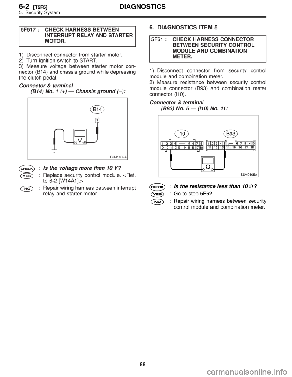
5F517 : CHECK HARNESS BETWEEN
INTERRUPT RELAY AND STARTER
MOTOR.
1) Disconnect connector from starter motor.
2) Turn ignition switch to START.
3) Measure voltage between starter motor con-
nector (B14) and chassis ground while depressing
the clutch pedal.
Connector & terminal
(B14) No. 1 (+) Ð Chassis ground (þ):
B6M1002A
:Is the voltage more than 10 V?
: Replace security control module.
to 6-2 [W14A1].>
: Repair wiring harness between interrupt
relay and starter motor.
6. DIAGNOSTICS ITEM 5
5F61 : CHECK HARNESS CONNECTOR
BETWEEN SECURITY CONTROL
MODULE AND COMBINATION
METER.
1) Disconnect connector from security control
module and combination meter.
2) Measure resistance between security control
module connector (B93) and combination meter
connector (i10).
Connector & terminal
(B93) No. 5 Ð (i10) No. 11:
S6M0465A
:Is the resistance less than 10W?
: Go to step5F62.
: Repair wiring harness between security
control module and combination meter.
88
6-2[T5F5]DIAGNOSTICS
5. Security System