Page 127 of 345

4F28 : CHECK RESISTANCE BETWEEN
HORN RELAY AND KEYLESS
ENTRY CONTROL MODULE.
1) Disconnect connector from main fuse box and
keyless entry control module.
2) Measure resistance between keyless entry con-
trol module connector (B176) and main fuse box
connector (F37).
Connector & terminal
(B176) No. 12 Ð (F37) No. 4:
B6M1352A
:Is the resistance less than 10W?
: Replace keyless entry control module.
: Repair wiring harness between main
fuse box and keyless entry control mod-
ule.
3. DIAGNOSTICS ITEM 2
4F31 : CHECK FUSE.
Remove and visually check the fuse No. 2 (in main
fuse box).
:Is fuse No. 2 blown?
: Replace fuse (15 A).
: Go to step4F32.
4F32 : CHECK ROOM LIGHT BULB.
Remove and visually check the room light bulb.
:Is the bulb blown?
: Replace bulb.
: Go to step4F33.
4F33 : CHECK ROOM LIGHT SWITCH.
1) Remove room light.
2) Measure resistance of room light switch termi-
nal at the middle position.
Terminals
No. 2 Ð No. 3:
B6M0960A
:Is the resistance less than 1W?
: Repair or replace room light.
: Go to step4F34.
65
[T4F3]6-2DIAGNOSTICS
4. Keyless Entry System
Page 130 of 345

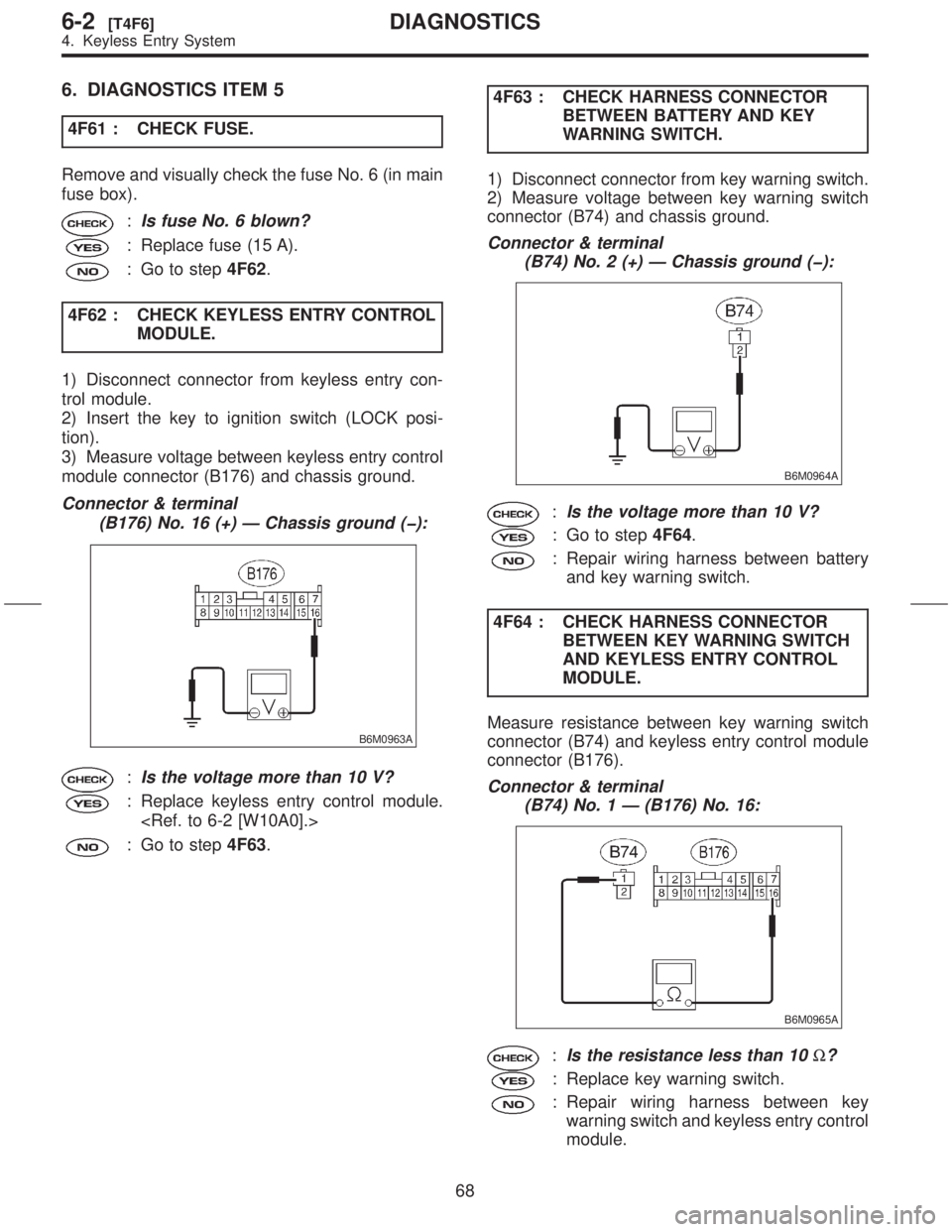
6. DIAGNOSTICS ITEM 5
4F61 : CHECK FUSE.
Remove and visually check the fuse No. 6 (in main
fuse box).
:Is fuse No. 6 blown?
: Replace fuse (15 A).
: Go to step4F62.
4F62 : CHECK KEYLESS ENTRY CONTROL
MODULE.
1) Disconnect connector from keyless entry con-
trol module.
2) Insert the key to ignition switch (LOCK posi-
tion).
3) Measure voltage between keyless entry control
module connector (B176) and chassis ground.
Connector & terminal
(B176) No. 16 (+) Ð Chassis ground (þ):
B6M0963A
:Is the voltage more than 10 V?
: Replace keyless entry control module.
: Go to step4F63.4F63 : CHECK HARNESS CONNECTOR
BETWEEN BATTERY AND KEY
WARNING SWITCH.
1) Disconnect connector from key warning switch.
2) Measure voltage between key warning switch
connector (B74) and chassis ground.
Connector & terminal
(B74) No. 2 (+) Ð Chassis ground (þ):
B6M0964A
:Is the voltage more than 10 V?
: Go to step4F64.
: Repair wiring harness between battery
and key warning switch.
4F64 : CHECK HARNESS CONNECTOR
BETWEEN KEY WARNING SWITCH
AND KEYLESS ENTRY CONTROL
MODULE.
Measure resistance between key warning switch
connector (B74) and keyless entry control module
connector (B176).
Connector & terminal
(B74) No. 1 Ð (B176) No. 16:
B6M0965A
:Is the resistance less than 10W?
: Replace key warning switch.
: Repair wiring harness between key
warning switch and keyless entry control
module.
68
6-2[T4F6]DIAGNOSTICS
4. Keyless Entry System
Page 131 of 345

5. Security System
A: PRECAUTION
1. SUPPLEMENTAL RESTRAINT SYSTEM
ªAIRBAGº
Airbag system wiring harness is routed near the
security control module.
CAUTION:
IAll airbag system wiring harness and con-
nectors are yellow. Do not use electrical test
equipment on these circuits.
IBe careful not to damage airbag system wir-
ing harness when servicing the security con-
trol module.
B: PRE-INSPECTION
1. FUSE
5B11 : CHECK FUSE.
Remove and visually check the fuse No. 7 (in main
fuse box).
:Is fuse No. 7 blown?
: Replace fuse (20 A).
: Go to step5B12.
5B12 : CHECK FUSE.
Remove and visually check the fuse No. 2 (in main
fuse box).
:Is fuse No. 2 blown?
: Replace fuse (15 A).
: Go to step5B21.
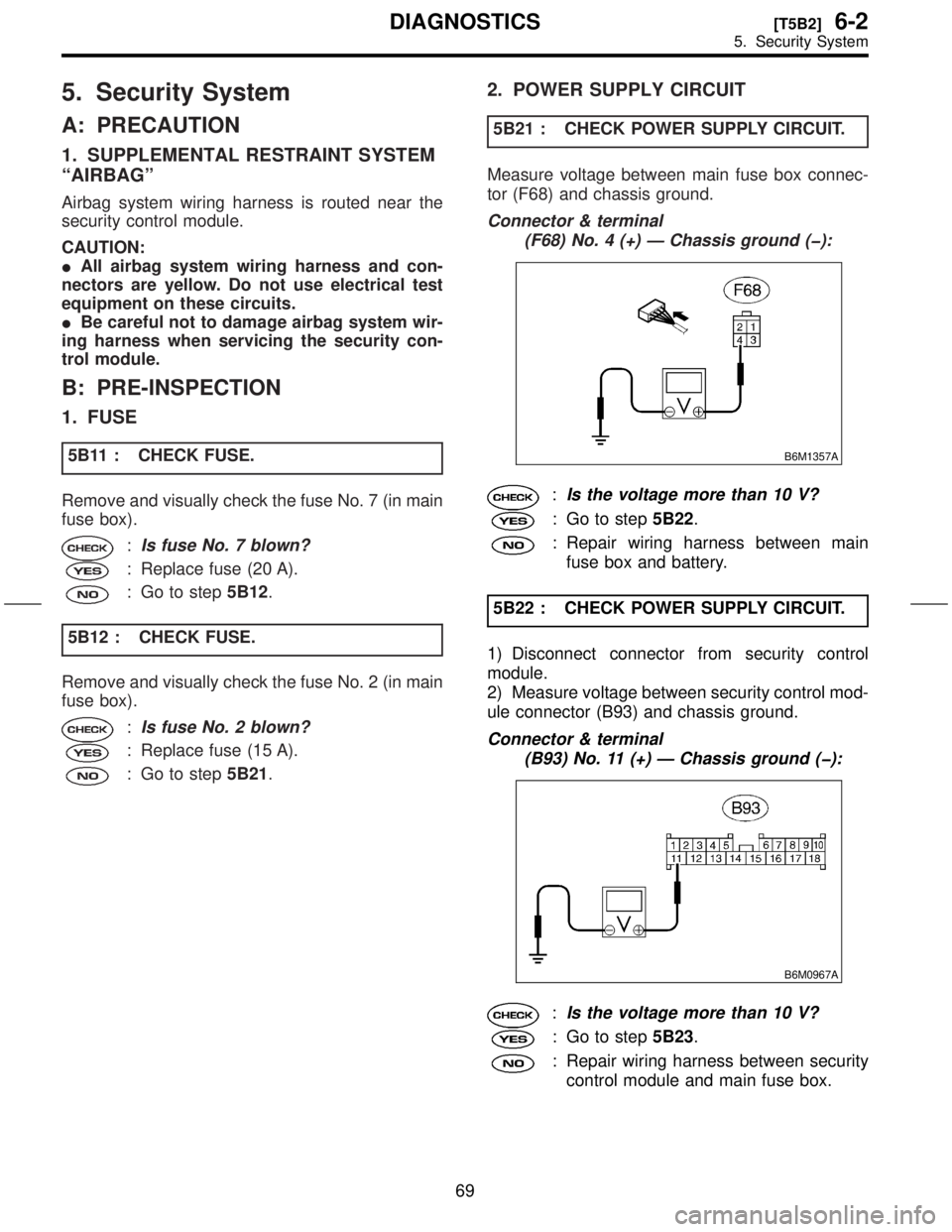
2. POWER SUPPLY CIRCUIT
5B21 : CHECK POWER SUPPLY CIRCUIT.
Measure voltage between main fuse box connec-
tor (F68) and chassis ground.
Connector & terminal
(F68) No. 4 (+) Ð Chassis ground (þ):
B6M1357A
:Is the voltage more than 10 V?
: Go to step5B22.
: Repair wiring harness between main
fuse box and battery.
5B22 : CHECK POWER SUPPLY CIRCUIT.
1) Disconnect connector from security control
module.
2) Measure voltage between security control mod-
ule connector (B93) and chassis ground.
Connector & terminal
(B93) No. 11 (+) Ð Chassis ground (þ):
B6M0967A
:Is the voltage more than 10 V?
: Go to step5B23.
: Repair wiring harness between security
control module and main fuse box.
69
[T5B2]6-2DIAGNOSTICS
5. Security System
Page 132 of 345
5B23 : CHECK POWER SUPPLY CIRCUIT.
Measure voltage between main fuse box connec-
tor (F68) and chassis ground.
Connector & terminal
(F68) No. 2 (+) Ð Chassis ground (þ):
B6M1358A
:Is the voltage more than 10 V?
: Go to step5B24.
: Repair wiring harness between main
fuse box and battery.
5B24 : CHECK POWER SUPPLY CIRCUIT.
Measure voltage between security control module
connector (B93) and chassis ground.
Connector & terminal
(B93) No. 13 (+) Ð Chassis ground (þ):
B6M0968A
:Is the voltage more than 10 V?
: Go to step5B31.
: Repair wiring harness between security
control module and main fuse box.
3. GROUND CIRCUIT
5B31 : CHECK GROUND CIRCUIT.
Measure resistance between security control mod-
ule connector (B93) and chassis ground.
Connector & terminal
(B93) No. 14 (+) Ð Chassis ground:
B6M0969A
:Is the resistance less than 10W?
: Go to step5F11.
: Repair wiring harness between security
control module and chassis ground.
70
6-2[T5B2]DIAGNOSTICS
5. Security System
Page 133 of 345
C: ELECTRICAL COMPONENTS LOCATION
S6M0454A
(1) Horn
(2) Keyless entry control module
(3) Security control module (under
console box)
(4) Security indicator light (in combi-
nation meter)(5) Horn relay (in main fuse box)
(6) Rear gate latch switch
(7) Interrupt relay (behind the fuse
box)
(8) Door switch(9) Passive arm connector (on driver
side front lower pillar)
71
[T5C0]6-2DIAGNOSTICS
5. Security System
Page 139 of 345
![SUBARU FORESTER 1999 Service Repair Manual 5F117 : CHECK PASSIVE ARM.
1) Remove the drivers side sill cover. <Ref. to 5-3
[W5A0].>
2) Connect the white connector (1-pin) at driver
side front lower pillar.
3) Close all doors and the rear gate. SUBARU FORESTER 1999 Service Repair Manual 5F117 : CHECK PASSIVE ARM.
1) Remove the drivers side sill cover. <Ref. to 5-3
[W5A0].>
2) Connect the white connector (1-pin) at driver
side front lower pillar.
3) Close all doors and the rear gate.](/manual-img/17/57427/w960_57427-138.png)
5F117 : CHECK PASSIVE ARM.
1) Remove the driver's side sill cover.
[W5A0].>
2) Connect the white connector (1-pin) at driver
side front lower pillar.
3) Close all doors and the rear gate.
:Does the arming automatically func-
tion after 1 minute?
: Go to step5F118.
: Go to step5 F 111.
5F118 : CHECK BATTERY DISCONNECT
PROTECTION.
1) Press the UNLOCK/DISARM button.
2) Connect the white connector (1-pin) at front pil-
lar lower.
3) Install the driver's side sill cover.
[W5A0].>
4) Open the front hood.
5) Press the LOCK/ARM button.
6) Disconnect the ground cable from battery.
7) Connect the ground cable to battery.
:Does re-arming function automati-
cally?
: End of basic diagnostics procedure.
Press the UNLOCK/DISARM button,
and then close all doors and the rear
gate. Perform ignition switch position
turned LOCK to ON to LOCK.
: Replace security control module.
to 6-2 [W14A1].>
2. DIAGNOSTICS ITEM 1
5F21 : CHECK FUSE.
Remove and visually check fuse No. 7 (in main
fuse box).
:Is fuse No. 7 blown?
: Replace fuse (20 A).
: Go to step5F22.
5F22 : CHECK FUSE.
Remove and visually check fuse No. 5 (in fuse
box).
:Is fuse No. 5 blown?
: Replace fuse (10 A).
: Go to step5F23.
5F23 : CHECK CLEARANCE LIGHT BULB.
Remove and visually check each clearance light
bulb.
:Is the bulb blown?
: Replace clearance light bulb.
: Go to step5F24.
5F24 : CHECK POWER SUPPLY FOR
CLEARANCE LIGHT.
Measure voltage between main fuse box connec-
tor (F68) and chassis ground.
Connector & terminal
(F68) No. 4 (+) Ð Chassis ground (þ):
B6M1357A
:Is the voltage more than 10 V?
: Go to step5F25.
: Repair wiring harness between main
fuse box and battery.
77
[T5F2]6-2DIAGNOSTICS
5. Security System
Page 140 of 345

5F25 : CHECK POWER SUPPLY FOR
CLEARANCE LIGHT.
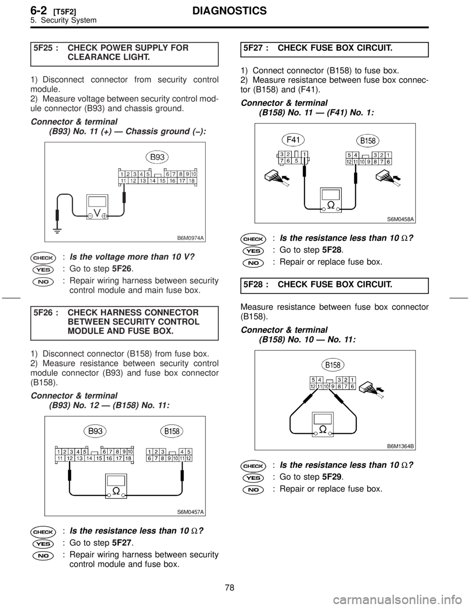
1) Disconnect connector from security control
module.
2) Measure voltage between security control mod-
ule connector (B93) and chassis ground.
Connector & terminal
(B93) No. 11 (+) Ð Chassis ground (þ):
B6M0974A
:Is the voltage more than 10 V?
: Go to step5F26.
: Repair wiring harness between security
control module and main fuse box.
5F26 : CHECK HARNESS CONNECTOR
BETWEEN SECURITY CONTROL
MODULE AND FUSE BOX.
1) Disconnect connector (B158) from fuse box.
2) Measure resistance between security control
module connector (B93) and fuse box connector
(B158).
Connector & terminal
(B93) No. 12 Ð (B158) No. 11:
S6M0457A
:Is the resistance less than 10W?
: Go to step5F27.
: Repair wiring harness between security
control module and fuse box.5F27 : CHECK FUSE BOX CIRCUIT.
1) Connect connector (B158) to fuse box.
2) Measure resistance between fuse box connec-
tor (B158) and (F41).
Connector & terminal
(B158) No. 11 Ð (F41) No. 1:
S6M0458A
:Is the resistance less than 10W?
: Go to step5F28.
: Repair or replace fuse box.
5F28 : CHECK FUSE BOX CIRCUIT.
Measure resistance between fuse box connector
(B158).
Connector & terminal
(B158) No. 10 Ð No. 11:
B6M1364B
:Is the resistance less than 10W?
: Go to step5F29.
: Repair or replace fuse box.
78
6-2[T5F2]DIAGNOSTICS
5. Security System
Page 141 of 345

5F29 : CHECK HARNESS CONNECTOR
BETWEEN FRONT CLEARANCE
LIGHT AND FUSE BOX.
1) Disconnect connector from front clearance light
RH and fuse box.
2) Measure resistance between front clearance
light RH connector (F3) and fuse box connector
(F41).
Connector & terminal
(F3) No. 1 Ð (F41) No. 1:
B6M1365B
:Is the resistance less than 10W?
: Go to step5F210.
: Repair wiring harness between front
clearance light RH and fuse box.5F210 : CHECK HARNESS CONNECTOR
BETWEEN FRONT CLEARANCE
LIGHT AND FUSE BOX.
1) Disconnect connector from front clearance light
LH.
2) Measure resistance between front clearance
light LH connector (F19) and fuse box connector
(F41).
Connector & terminal
(F19) No. 1 Ð (F41) No. 1:
B6M1366B
:Is the resistance less than 10W?
: Go to step5F211.
: Repair wiring harness between front
clearance light LH and fuse box.
5F211 : CHECK HARNESS CONNECTOR
BETWEEN FRONT CLEARANCE
LIGHT AND CHASSIS GROUND.
Measure resistance between front clearance light
RH connector (F3) and chassis ground.
Connector & terminal
(F3) No. 2 (+) Ð Chassis ground (þ):
B6M0980C
:Is the resistance less than 10W?
: Go to step5F212.
: Repair wiring harness between front
clearance light RH and chassis ground.
79
[T5F2]6-2DIAGNOSTICS
5. Security System